Как создавать 3D-модели ювелирных изделий с помощью JewelCAD?

Learn how to make 3D jewelry models with JewelCAD. It's a powerful software for designing rings, pendants, and more. You can create different surface effects like sandblasting or brushing. It's easy to use and helps you design quickly. Perfect for jewelry stores, designers, and anyone making custom pieces.

Как создавать 3D-модели ювелирных изделий с помощью JewelCAD?

Understanding JewelCAD, Represent Basic Material Effects and Jewelry Effects

Введение:

What does it take to create stunning jewelry designs using JewelCAD? This guide covers everything from understanding the software to mastering material effects and crafting detailed jewelry models. Learn how to bring your ideas to life with step-by-step instructions for designing rings, pendants, and more. Discover why JewelCAD is a must-have tool for jewelry designers, studios, and brands looking to elevate their craft.
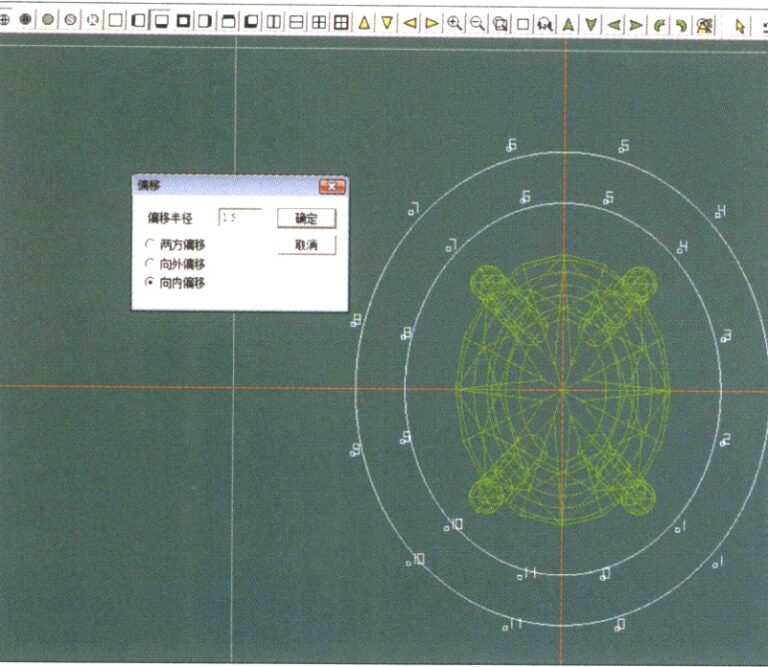
21. Войдите в диалоговое окно "Кривая смещения", введите соответствующие значения в качестве вспомогательных линий для внутренней окружности и подтвердите

Кольцо с бриллиантовой оправой

Оглавление

Section I Understanding JewelCAD

JewelCAD is a computer-aided design system software specifically for jewelry that was successfully developed by a Hong Kong CAD/CAM company in 1990. After over a decade of development and improvement, JewelCAD has evolved from a limited-function drawing software into a powerful, stable, highly specialized, and efficient, professional jewelry design/manufacturing software widely adopted in major jewelry production areas in Europe, America, and Asia.

While the automation of production and processing in the jewelry industry has significantly improved efficiency, JewelCAD matches modern jewelry design and has been widely disseminated in current commercial applications. Its unique modeling concepts and tools allow jewelry designers to easily create three-dimensional jewelry objects, and it also integrates perfectly with CNC and RP rapid prototyping, making it a modern jewelry design software with broad development prospects. As a professional jewelry design software, JewelCAD has clear advantages over other 3D software in creating three-dimensional models of jewelry, which is reflected in the following benefits.

(1) Easy to operate, simple, and easy to learn.

(2) It has flexible drawing tools, which are very convenient for drawing curves and complex shapes.

(3) It has powerful surface modeling tools that flexibly create or modify complex designs.

(4) The rendering speed is fast; you can also compare various design effect images. The quality of the effect images is high, and the simulation is strong. It allows rotating to observe the three-dimensional effect, intuitively reflecting the final product effect.

(5) Its operation is highly efficient and suitable for changing jewelry styles.

(6) A rich professional database and various editing tools facilitate the combination and redesign of jewelry, making operations more convenient and efficient.

(7) Applying the principles of Boolean operations in software can easily unite surfaces that are in a free state.

(8) In the design, the weight of the gold, quantity, and size can be calculated directly.

(9) Can build a database to visualize design ideas and improve efficiency.

(10) The graphics drawn with JewelCAD are clearer and more consistent, reducing the likelihood of errors caused by unclear writing or poor drawing quality. It can directly output paperless images, saving time, effort, and money.

Section II Using JewelCAD to Represent Basic Material Effects

The texture of the effect image does not need to be as realistic as a photograph. However, it should still allow the viewer to perceive the differences in textures, such as jewelry and metal, especially for materials with obvious visual effects. This section provides a detailed introduction to how to use JewelCAD to design and create jewelry, achieving a specific metal surface texture effect.

1. Sandblasting Finish Effect

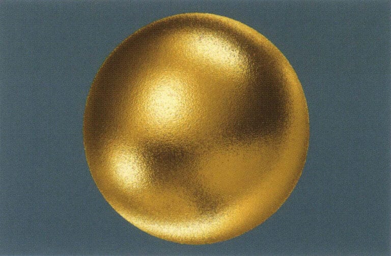
Sandblasting techniques include water sandblasting, fine grit blasting, manual blasting, contrast blasting, etc. This technique is often used for plain gold jewelry and is widely applied in pure gold. The sandblasted surface created on the surface gives the jewelry a matte diffuse reflection effect.
Sandblasting Finish Effect
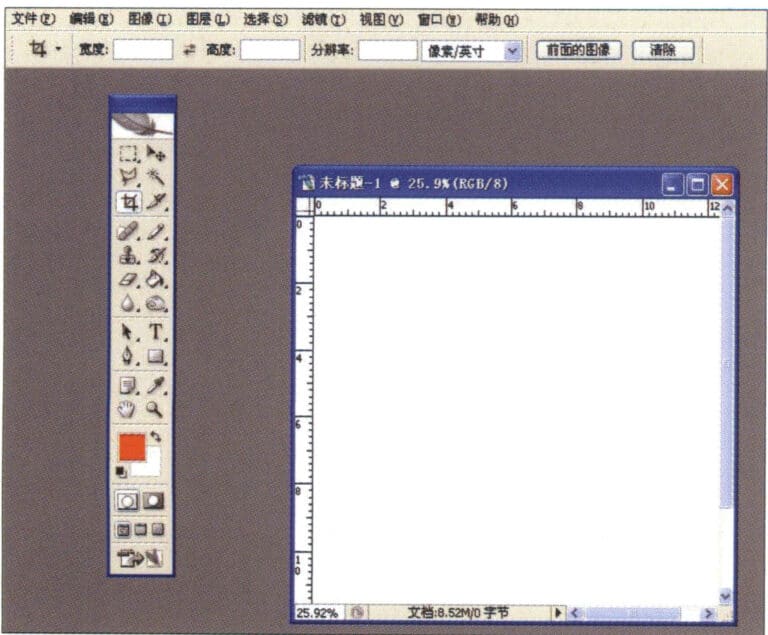
1. Create a new file in Photoshop with a resolution of 300 pixels/inch
1. Create a new file in Photoshop with a resolution of 300 pixels/inch

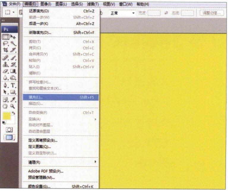
2. Select "Edit" > "Fill" from the menu bar, and set the foreground color to yellow

2. Select "Edit" > "Fill" from the menu bar, and set the foreground color to yellow

3. Select "Filter" from the menu bar > "Mottled" > "Add Mottled"
3. Select "Filter" from the menu bar > "Mottled" > "Add Mottled"

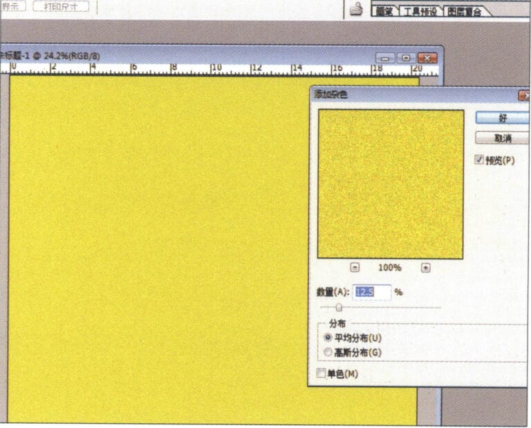
4. Enter the "Add Mottled" dialog box, input the relevant values, and confirm
4. Enter the "Add Mottled" dialog box, input the relevant values, and confirm

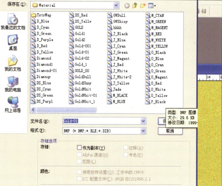
5. Store the document in the "JewelCAD" > "Material" folder, saved in "BMP" format

5. Store the document in the "JewelCAD" > "Material" folder, saved in "BMP" format

6. Create a new file in JewelCAD, select "Surface" > "Spherical Surface" from the menu bar
6. Create a new file in JewelCAD, select "Surface" > "Spherical Surface" from the menu bar

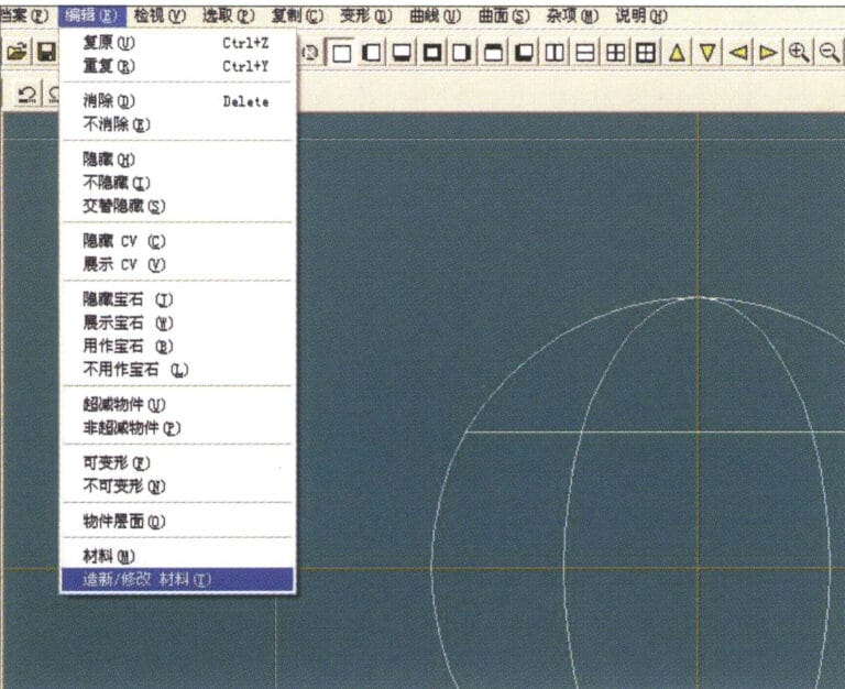
7. Select "Edit" > "Create/Modify Material" from the menu bar
7. Select "Edit" > "Create/Modify Material" from the menu bar

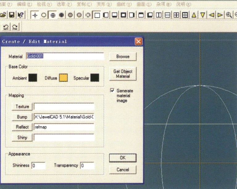
8. Enter the "Create/Modify Material" dialog box, input the relevant values, and confirm
8. Enter the "Create/Modify Material" dialog box, input the relevant values, and confirm

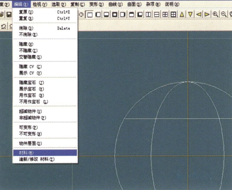
9. Select "Edit" > "Materials" from the menu bar
9. Select "Edit" > "Materials" from the menu bar

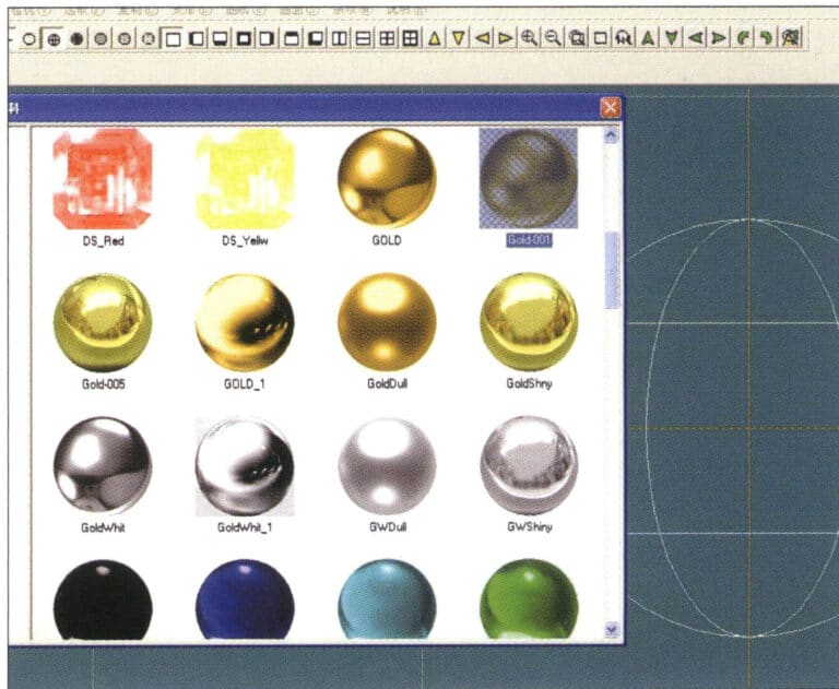
10. Enter the "Materials" dialog box, select the material and confirm
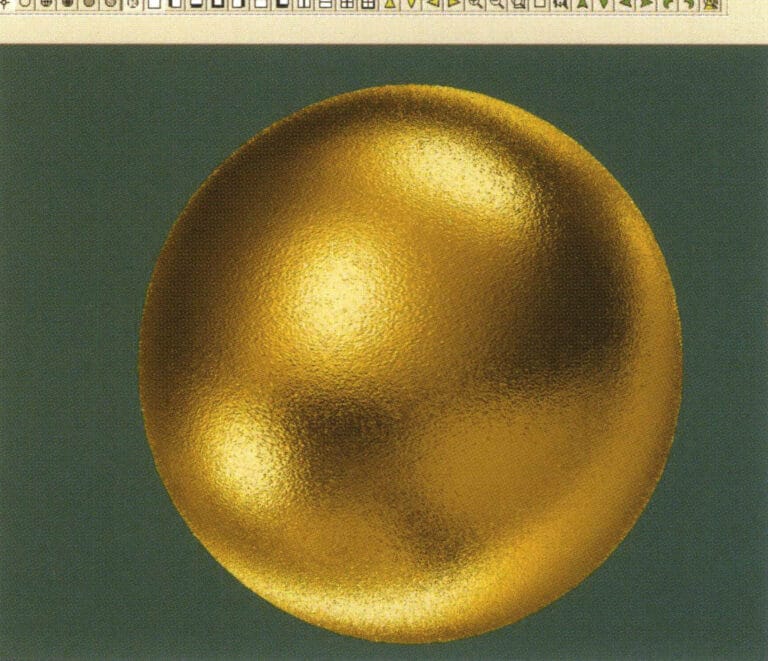
10. Enter the "Materials" dialog box, select the material and confirm

11. Select "View" > "Shadow Map" from the menu bar to inspect the shadow effects. 12. Select "File" > "Save File" from the menu bar to save the document

11. Select "View" > "Shadow Map" from the menu bar to inspect the shadow effects.

12. Select "File" > "Save File" from the menu bar to save the document

2. Brushing Effect
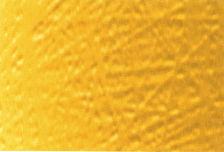
The brushed effect is often used on K gold and palladium jewelry, creating an elegant, streamlined matte finish on the surface of the pieces.
Brushing Effect
1. Scan a texture file in Photoshop with a resolution of 300 pixels/inch, and select "Filter" > "Blur" > "Motion Blur" from the menu bar to apply the blur effect
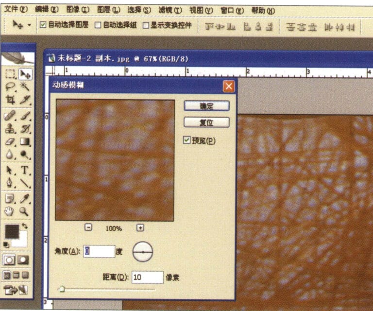
1. Scan a texture file in Photoshop with a resolution of 300 pixels/inch, and select "Filter" > "Blur" > "Motion Blur" from the menu bar to apply the blur effect

2. Enter the "Motion Blur" dialog box, input the relevant values, and confirm
2. Enter the "Motion Blur" dialog box, input the relevant values, and confirm

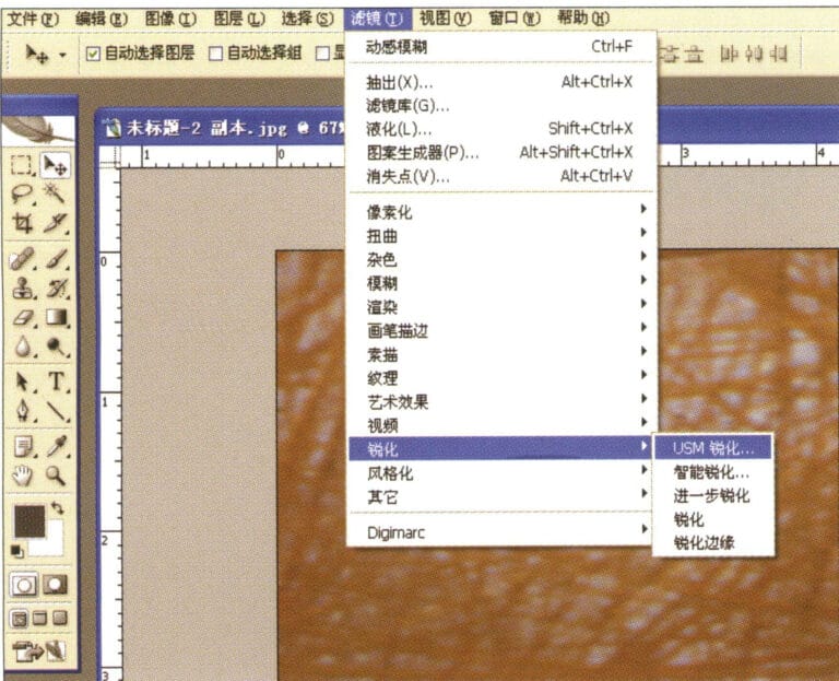
3. Select "Filter" > "Sharpen" > "USM Sharpening" from the menu bar
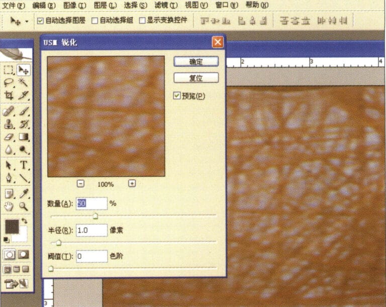
3. Select "Filter" > "Sharpen" > "USM Sharpening" from the menu bar

4. Enter the "USM Sharpening" dialog box, input the relevant values, and confirm
4. Enter the "USM Sharpening" dialog box, input the relevant values, and confirm

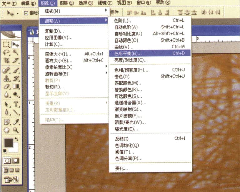
5. Select "Image" > "Adjustments" > "Color Balance" from the menu bar
5. Select "Image" > "Adjustments" > "Color Balance" from the menu bar

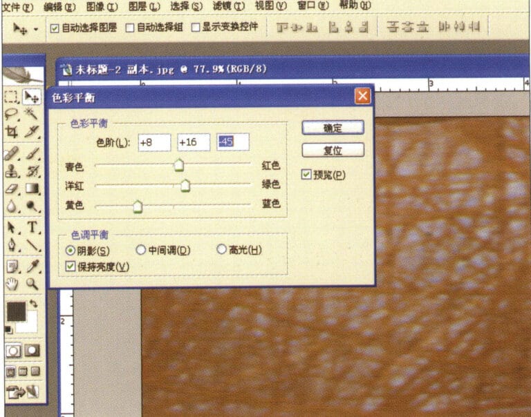
6. Enter the "Color Balance" dialog box, input the relevant values, and confirm
6. Enter the "Color Balance" dialog box, input the relevant values, and confirm

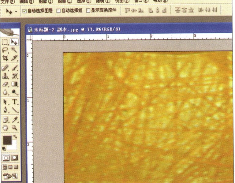
7. Effect diagram after displaying color balance
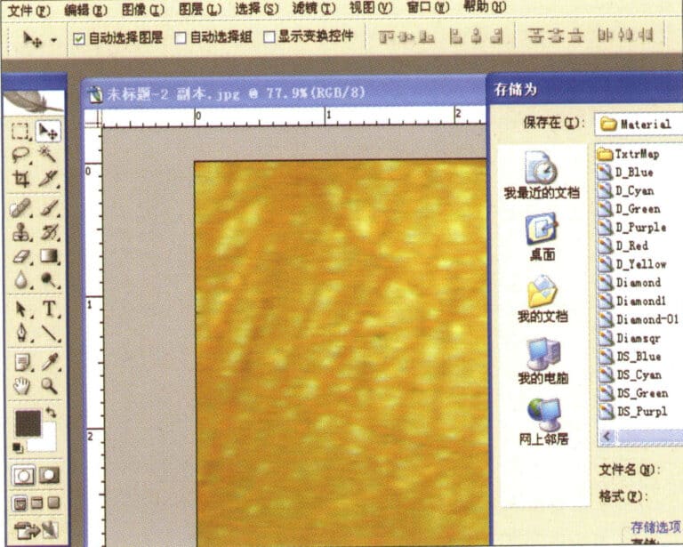
7. Effect diagram after displaying color balance

8. Store the document in the "JewelCAD" > "Material" folder, saved in "BMP" format
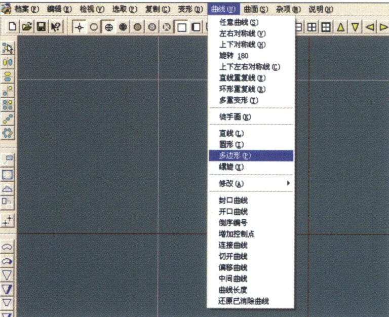
8. Store the document in the "JewelCAD" > "Material" folder, saved in "BMP" format

9. In JewelCAD, create a new file, select "Curve" > "Polygon" from the menu bar
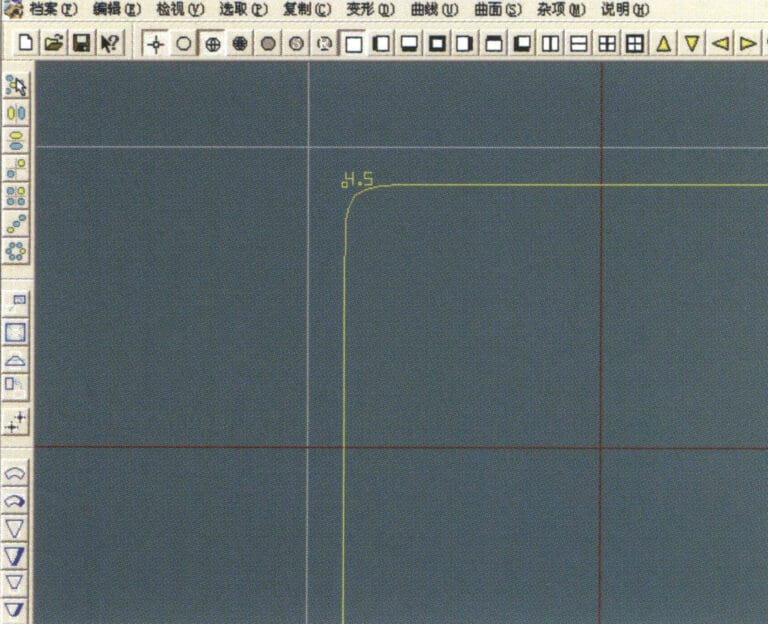
9. In JewelCAD, create a new file, select "Curve" > "Polygon" from the menu bar

10. Use "polygon" to draw a square
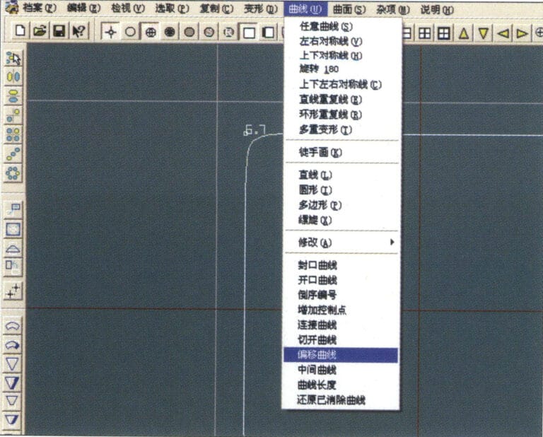
10. Use "polygon" to draw a square

11. Select "Curve" > "Offset Curve" from the menu bar
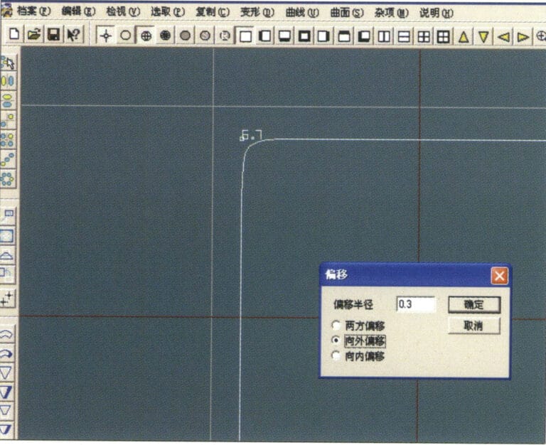
11. Select "Curve" > "Offset Curve" from the menu bar

12. Enter the "Offset Curve" dialog box, input the relevant values, and confirm
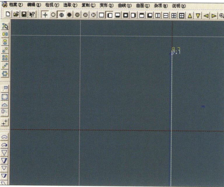
12. Enter the "Offset Curve" dialog box, input the relevant values, and confirm

13. Effect diagram after displaying the offset curve
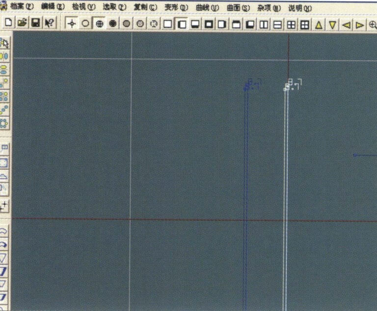
13. Effect diagram after displaying the offset curve

14. Select "Deformation" > "Move" from the menu bar to move the selected curve
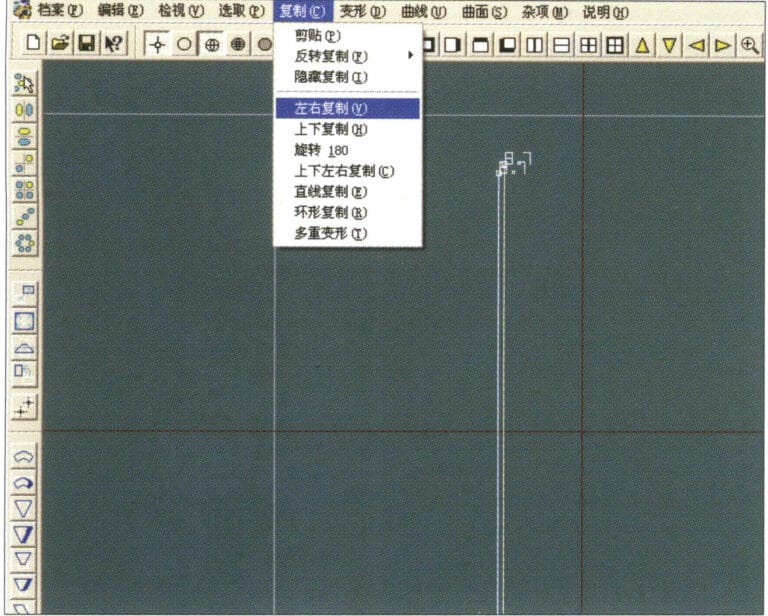
14. Select "Deformation" > "Move" from the menu bar to move the selected curve

15. Select "Copy" > "Copy Left and Right" from the menu bar to copy the selected curve to the left and right
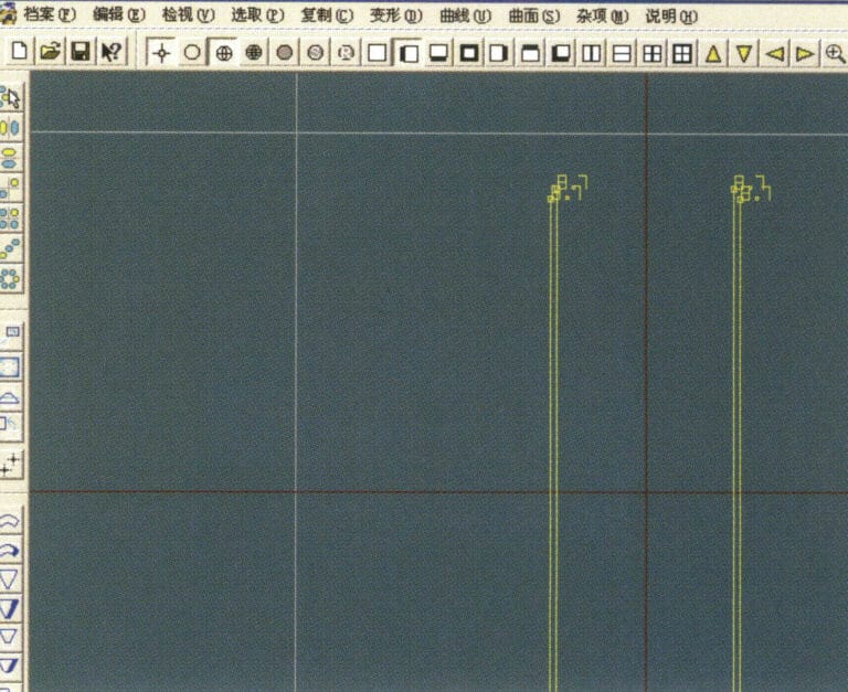
15. Select "Copy" > "Copy Left and Right" from the menu bar to copy the selected curve to the left and right

16. Display the effect images after left and right duplication
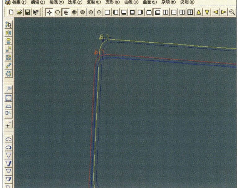
16. Display the effect images after left and right duplication

17. Select "Surface" > "Curve Surface Connection" from the menu bar, and double-click the first and second curves/surfaces in a clockwise direction with the left mouse button to create a curve surface connection
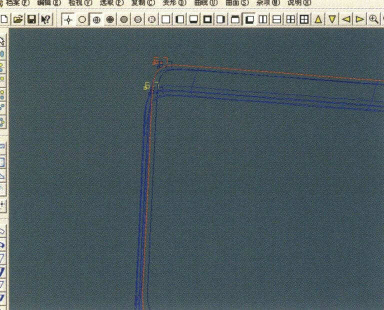
17. Select "Surface" > "Curve Surface Connection" from the menu bar, and double-click the first and second curves/surfaces in a clockwise direction with the left mouse button to create a curve surface connection

18. In a clockwise direction, double-click the third curve/surface with the left mouse button to create a line-surface connection
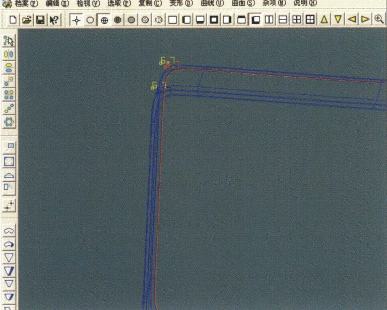
18. In a clockwise direction, double-click the third curve/surface with the left mouse button to create a line-surface connection

19. Continue clockwise; double-click the fourth curve/surface with the left mouse button to create a line-surface connection

19. Continue clockwise; double-click the fourth curve/surface with the left mouse button to create a line-surface connection

20. Select "View" > "Shadow Map" from the menu bar to inspect the shadow effects
20. Select "View" > "Shadow Map" from the menu bar to inspect the shadow effects

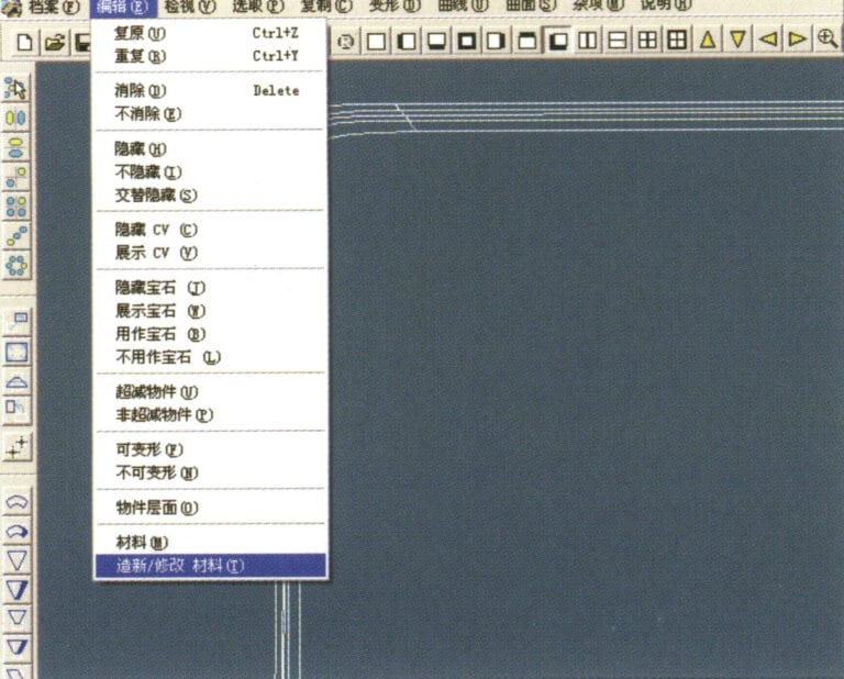
21. Select "Edit" > "Create/Modify Material" from the menu bar
21. Select "Edit" > "Create/Modify Material" from the menu bar

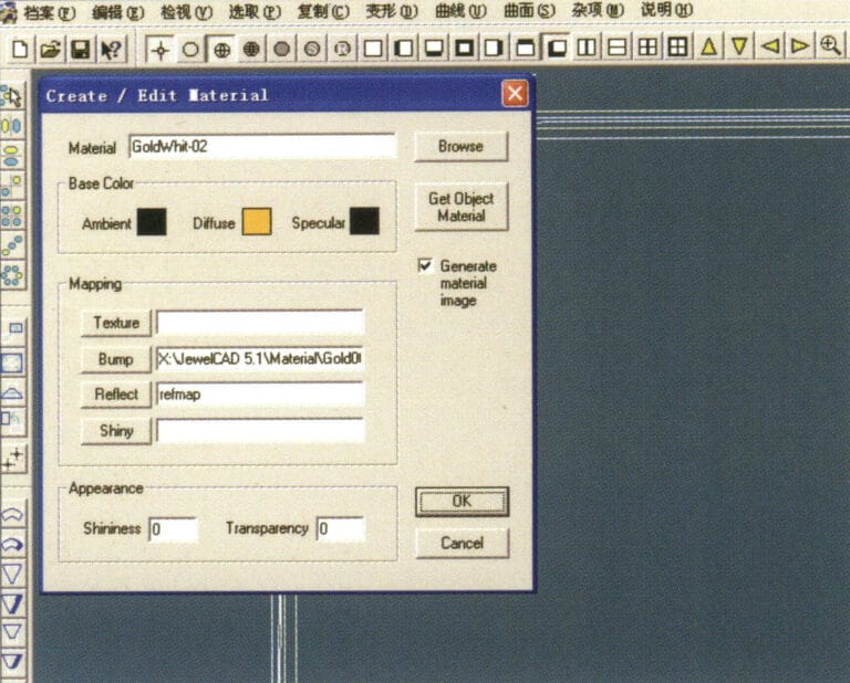
22. Enter the "Create/Modify Material" dialog box, input the relevant values, and confirm
22. Enter the "Create/Modify Material" dialog box, input the relevant values, and confirm

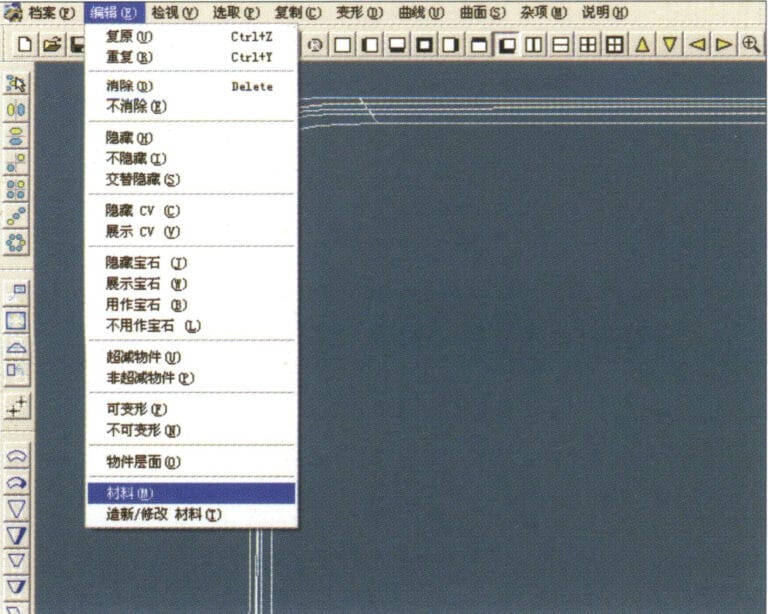
23. Select "Edit" > "Materials" from the menu bar
23. Select "Edit" > "Materials" from the menu bar

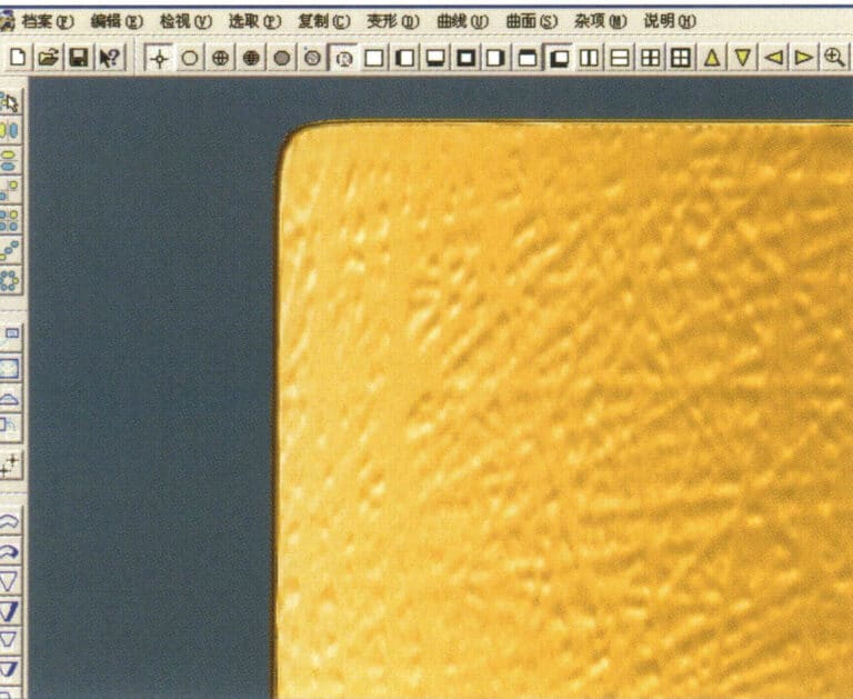
24. Select "View" > "Shadow Map" on the menu bar to view the light and shadow effects 25. Select "File" > "Save File" on the menu bar to save the file

24. Select "View" > "Shadow Map" on the menu bar to view the light and shadow effects 25. Select "File" > "Save File" on the menu bar to save the file

3. Bark Texture Finish
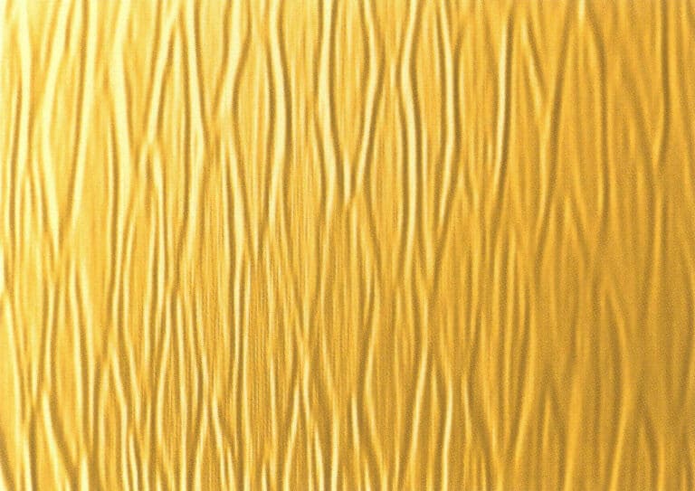
Bark effect is mostly used in silver jewelry, the surface to create bark texture to make the surface of the jewelry to form a rough texture effect.
Bark Texture Finish
1. Scan a texture file into Photoshop with a resolution of 300 pixels/inch
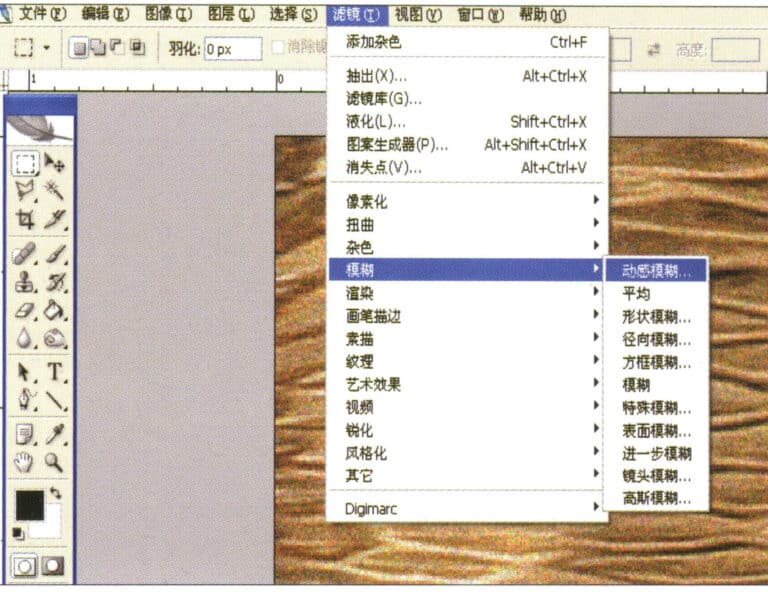
1. Scan a texture file into Photoshop with a resolution of 300 pixels/inch

2. Select "Filter" > "Blur" > "Motion Blur" from the menu bar
2. Select "Filter" > "Blur" > "Motion Blur" from the menu bar

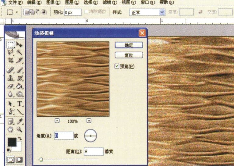
3. Enter the "Motion Blur" dialog box, input the relevant values, and confirm
3. Enter the "Motion Blur" dialog box, input the relevant values, and confirm

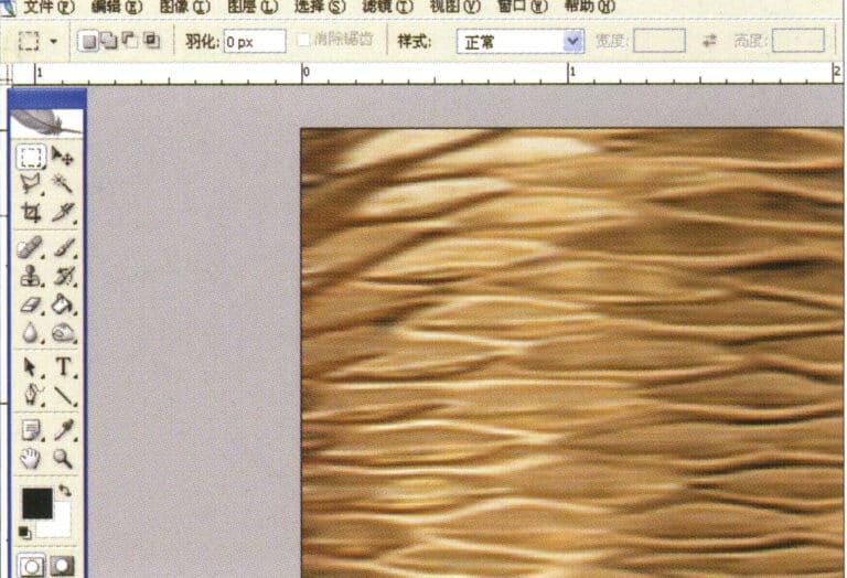
4. Display the effect image after motion blur
4. Display the effect image after motion blur

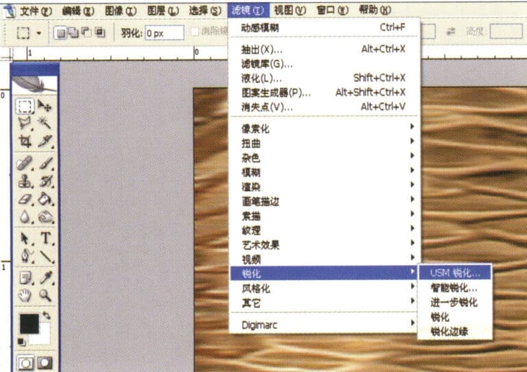
5. Select "Filter" > "Sharpen" > "USM Sharpening" from the menu bar
5. Select "Filter" > "Sharpen" > "USM Sharpening" from the menu bar

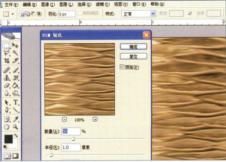
6. Enter the "USM Sharpening" dialog box, input the relevant values, and confirm
6. Enter the "USM Sharpening" dialog box, input the relevant values, and confirm

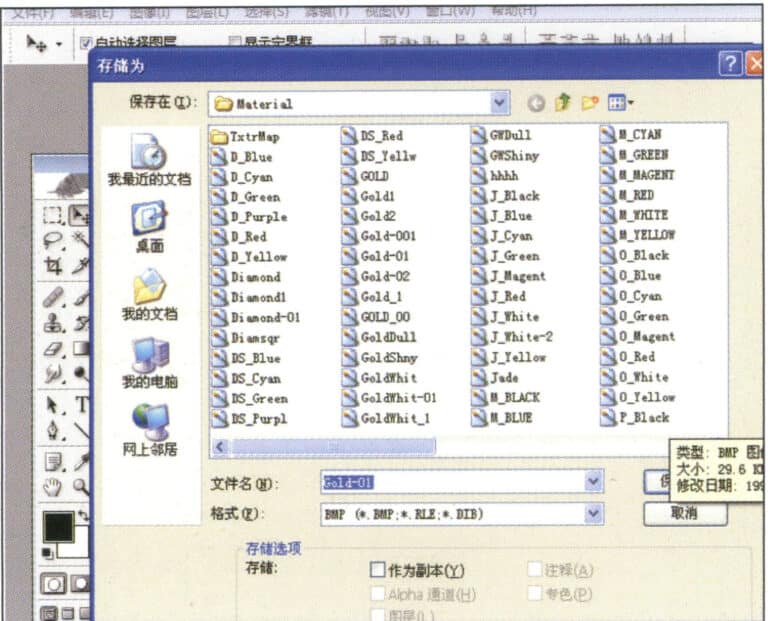
7. Store the document in the "JewelCAD" > "Material" folder and save it in "BMP" format
7. Store the document in the "JewelCAD" > "Material" folder and save it in "BMP" format

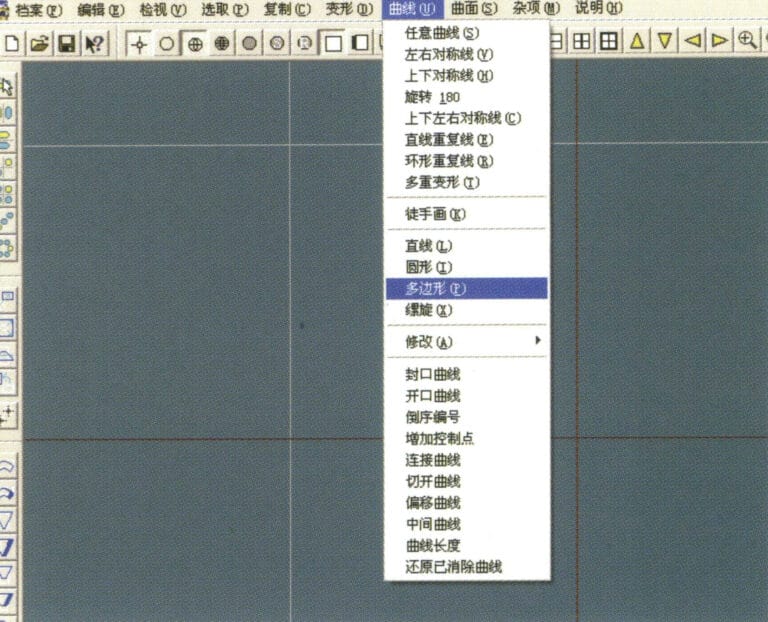
8. In JewelCAD, create a new file, select "Curve" > "Polygon" from the menu bar
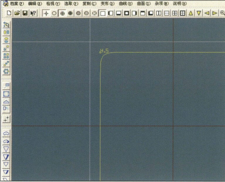
8. In JewelCAD, create a new file, select "Curve" > "Polygon" from the menu bar

9. Use "polygon" to draw a square
9. Use "polygon" to draw a square

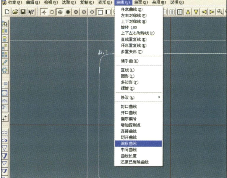
10. Select "Curve" > "Offset Curve" from the menu bar
10. Select "Curve" > "Offset Curve" from the menu bar

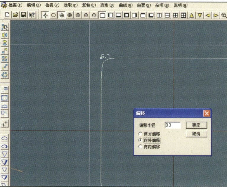
11. Enter the "Offset Curve" dialog box, input the relevant values, and confirm
11. Enter the "Offset Curve" dialog box, input the relevant values, and confirm

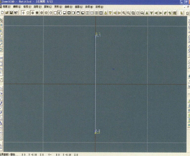
12. Effect diagram after displaying the offset curve
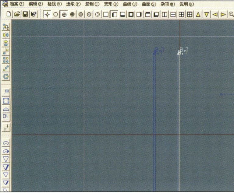
12. Effect diagram after displaying the offset curve

13. Select "Deformation" > "Move" from the menu bar to move the selected curve
13. Select "Deformation" > "Move" from the menu bar to move the selected curve

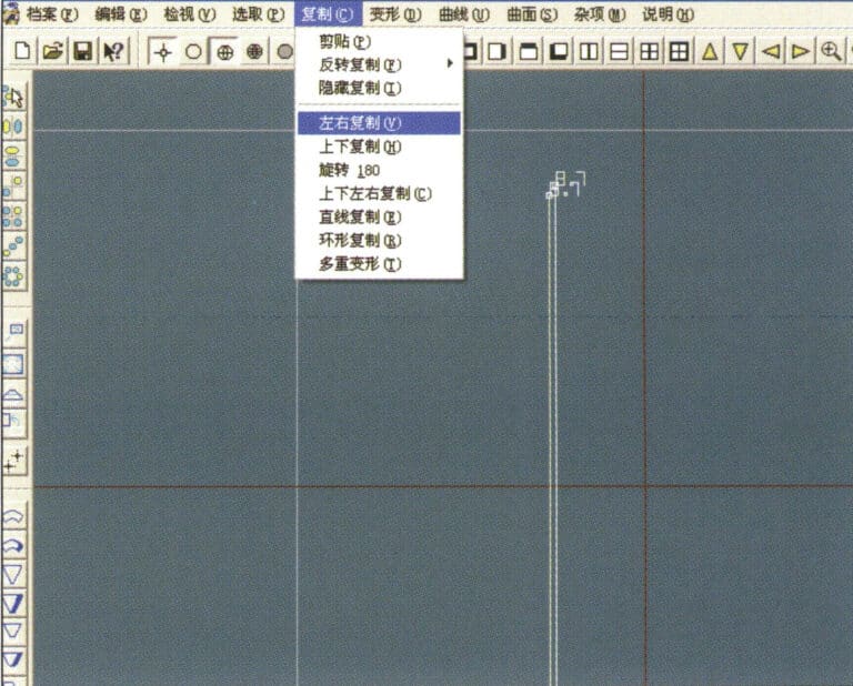
14. Select "Copy" > "Copy Left and Right" from the menu bar to copy the selected curve to the left and right
14. Select "Copy" > "Copy Left and Right" from the menu bar to copy the selected curve to the left and right

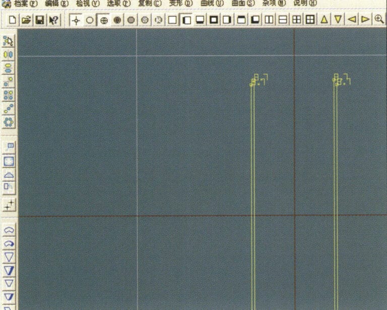
15. Display the effect images after copying left and right
15. Display the effect images after copying left and right

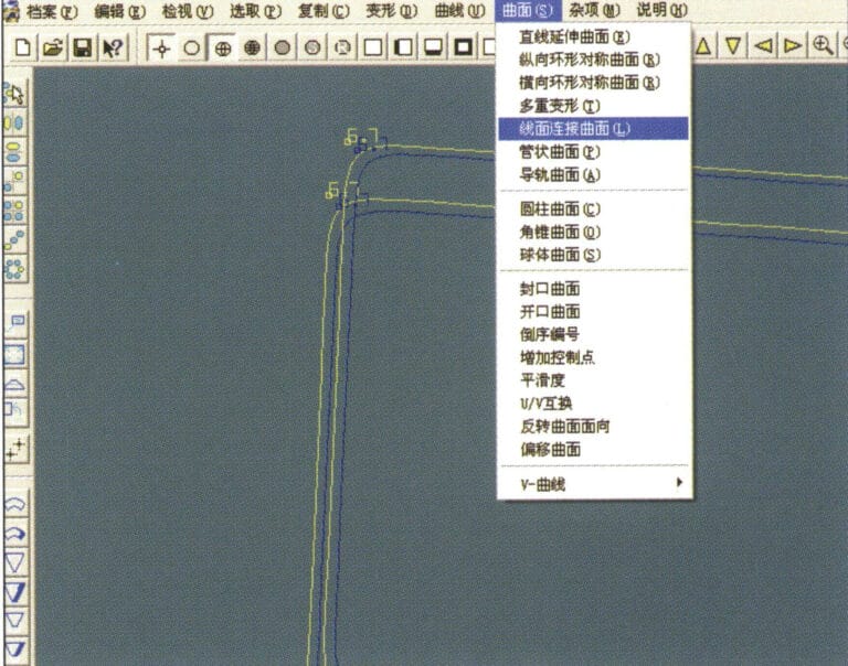
16. Select "Surface" > "Line-Surface Connection Surface" from the menu bar, and select the curve/surface to create a line-surface connection surface
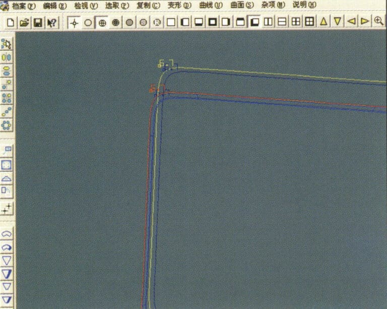
16. Select "Surface" > "Line-Surface Connection Surface" from the menu bar, and select the curve/surface to create a line-surface connection surface

17. Select the menu bar "Surface" > "Curve Surface Connection," and double-click the first and second curves/surfaces with the left mouse button in a clockwise direction to create a curve surface connection
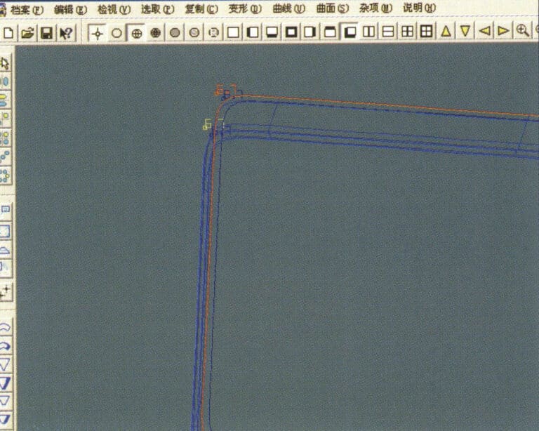
17. Select the menu bar "Surface" > "Curve Surface Connection," and double-click the first and second curves/surfaces with the left mouse button in a clockwise direction to create a curve surface connection

18. In a clockwise direction, double-click the third curve/surface with the left mouse button to create a line-surface connection
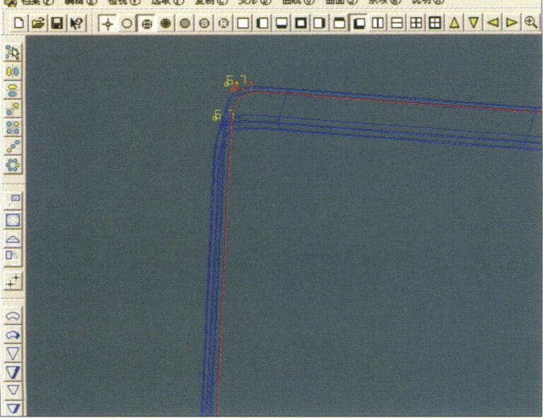
18. In a clockwise direction, double-click the third curve/surface with the left mouse button to create a line-surface connection

19. Continue clockwise; double-click the fourth curve/surface with the left mouse button to create a line-surface connection
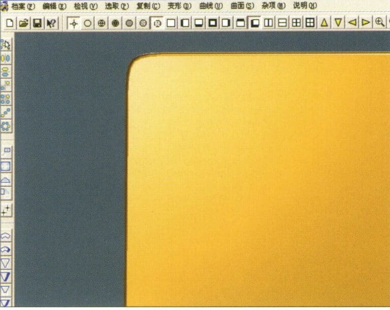
19. Continue clockwise; double-click the fourth curve/surface with the left mouse button to create a line-surface connection

20. Select "View" > "Shadow Map" from the menu bar to inspect the shadow effects
20. Select "View" > "Shadow Map" from the menu bar to inspect the shadow effects

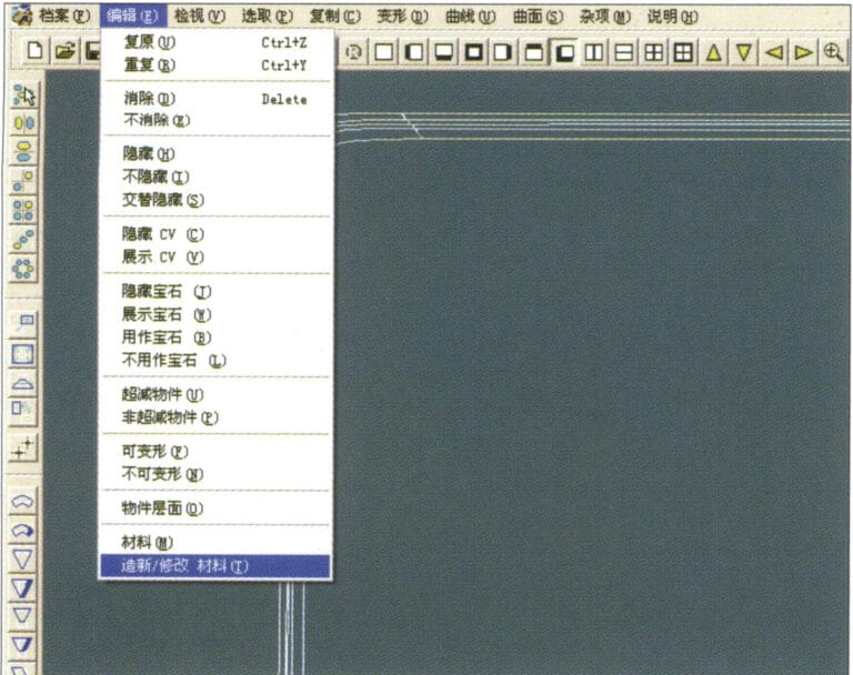
21. Select "Edit" > "Create/Modify Material" from the menu bar
21. Select "Edit" > "Create/Modify Material" from the menu bar

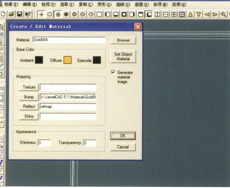
22. Enter the "Create/Modify Material" dialog box, input the relevant values, and confirm
22. Enter the "Create/Modify Material" dialog box, input the relevant values, and confirm

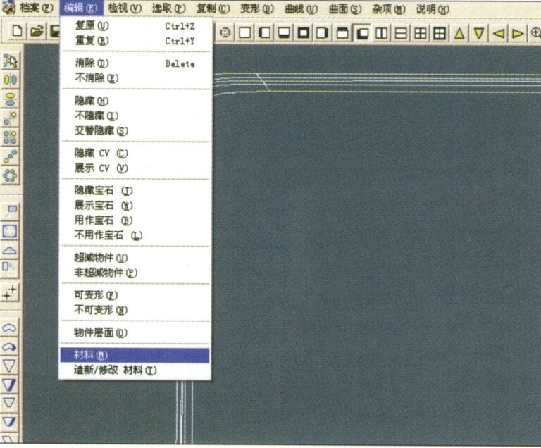
23. Select “Edit” > “Material” in the menu bar
23. Select “Edit” > “Material” in the menu bar

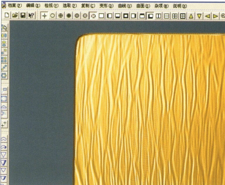
24. Select "View" > "Shadow Map" from the menu bar to examine the shadow effects 25. Select "File" > "Save As" from the menu bar to save the file

24. Select "View" > "Shadow Map" from the menu bar to examine the shadow effects

25. Select "File" > "Save As" from the menu bar to save the file

4. Engine-Turned Finish
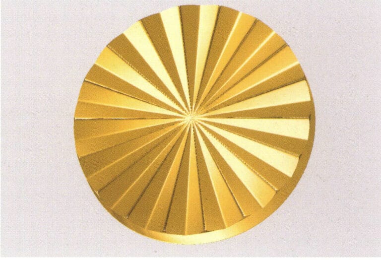
The forms of engine-turned finish are diverse, including rice-shaped and cross-shaped designs. This craft effect is mostly used in plain gold jewelry, where the engine-turned surface created makes the jewelry’s surface exhibit a dazzling brilliance under the refraction of light.
Engine-Turned Finish
1. Create a new file in JewelCAD, select "Curve" > "Circular Curve" from the menu bar, enter the relevant values in the "Circular Curve" dialog box, and confirm
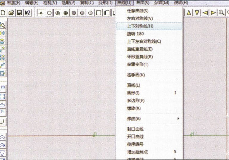
1. Create a new file in JewelCAD, select "Curve" > "Circular Curve" from the menu bar, enter the relevant values in the "Circular Curve" dialog box, and confirm

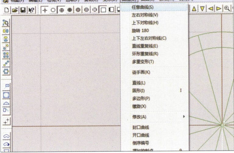
2. Select "Curve" > "Left-Right Symmetry Line" from the menu bar to draw a section
2. Select "Curve" > "Left-Right Symmetry Line" from the menu bar to draw a section

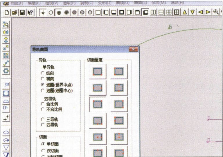
3. Select "Surface" > "Rail Surface" from the menu bar, enter "Rail Surface," select the relevant options and confirm; left-click on a curve as the section of the rail surface; left-click on another curve as the "Rail" > "Finish."

3. Select "Surface" > "Rail Surface" from the menu bar, enter "Rail Surface," select the relevant options and confirm; left-click on a curve as the section of the rail surface; left-click on another curve as the "Rail" > "Finish."

4. Select “View” > “Shadow Map” on the menu bar to view the light and shadow effects
4. Select “View” > “Shadow Map” on the menu bar to view the light and shadow effects

5. Select "Curve" > "Freefrom Curve" from the menu bar
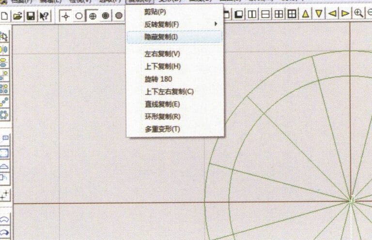
5. Select "Curve" > "Freefrom Curve" from the menu bar

6. Select "Copy" > "Hide Copy" from the menu bar
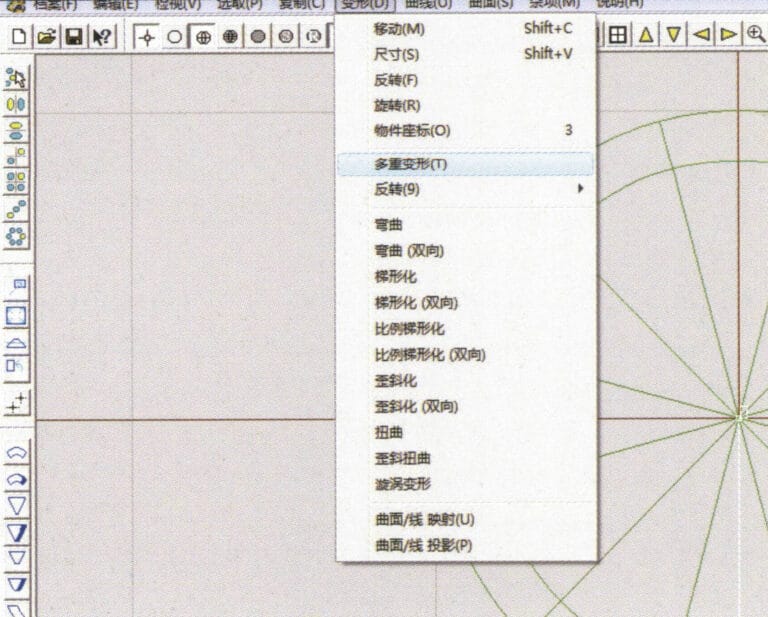
6. Select "Copy" > "Hide Copy" from the menu bar

7. Select "Deformation" > "Multiple Deformation" from the menu bar
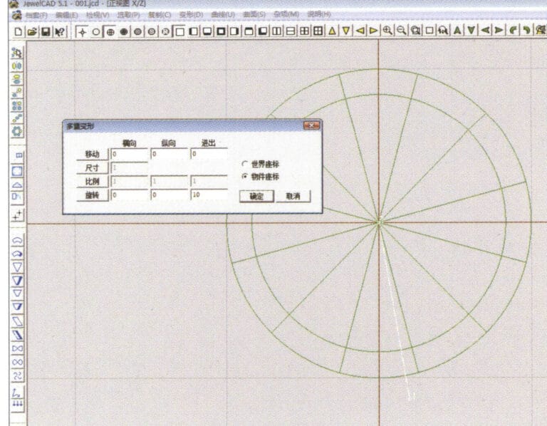
7. Select "Deformation" > "Multiple Deformation" from the menu bar

8. Enter the "Multiple Deformation" dialog box and input the relevant values
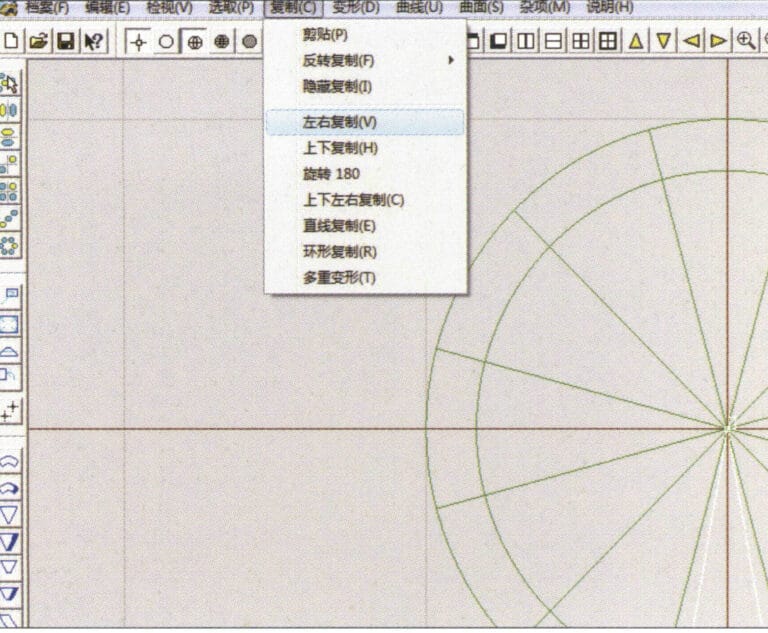
8. Enter the "Multiple Deformation" dialog box and input the relevant values

9. Select “Copy” > “Left/Right Copy” on the menu bar
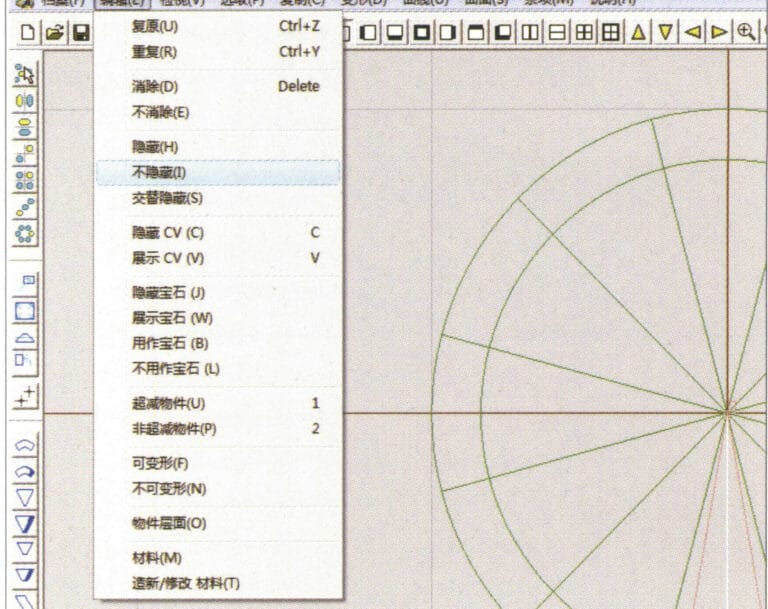
9. Select “Copy” > “Left/Right Copy” on the menu bar

10. Select "Edit" > "Unhide" from the menu bar to display the hidden curves
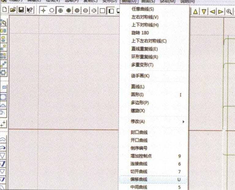
10. Select "Edit" > "Unhide" from the menu bar to display the hidden curves

11. Select "Curve" > "Offset Curve" from the menu bar
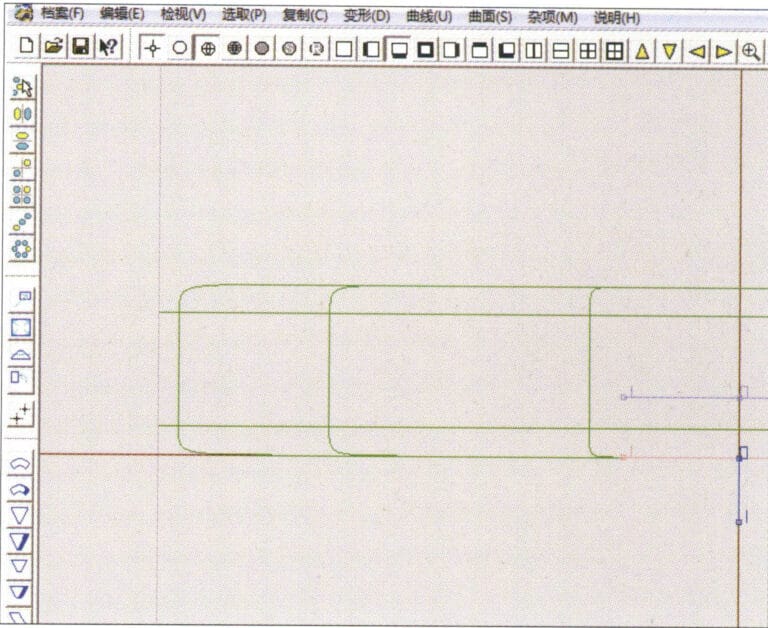
11. Select "Curve" > "Offset Curve" from the menu bar

12. Select "Deformation" > "Move" from the menu bar to move the selected curve
12. Select "Deformation" > "Move" from the menu bar to move the selected curve

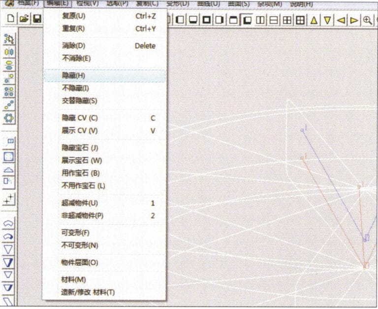
13. Select "Edit" > "Hide" from the menu bar to hide the circular surface
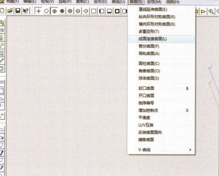
13. Select "Edit" > "Hide" from the menu bar to hide the circular surface

14. Select "Surface" > "Line Surface Connection Surface" from the menu bar

14. Select "Surface" > "Line Surface Connection Surface" from the menu bar

15. Select curves/surfaces in a clockwise direction to create line-surface connections, then select from the menu bar
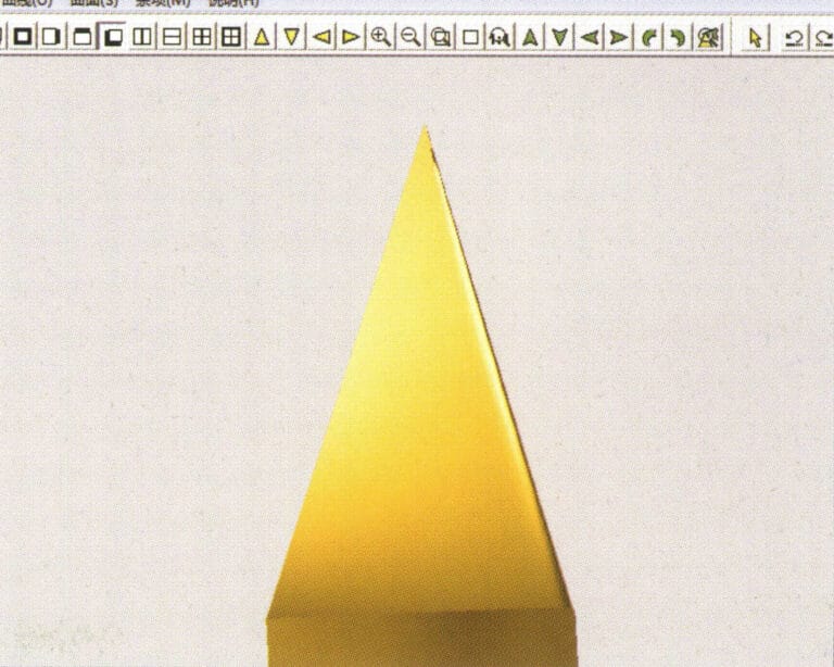
15. Select curves/surfaces in a clockwise direction to create line-surface connections, then select from the menu bar

16. Select "View" > "Shadow Map" from the menu bar to inspect the shadow effects
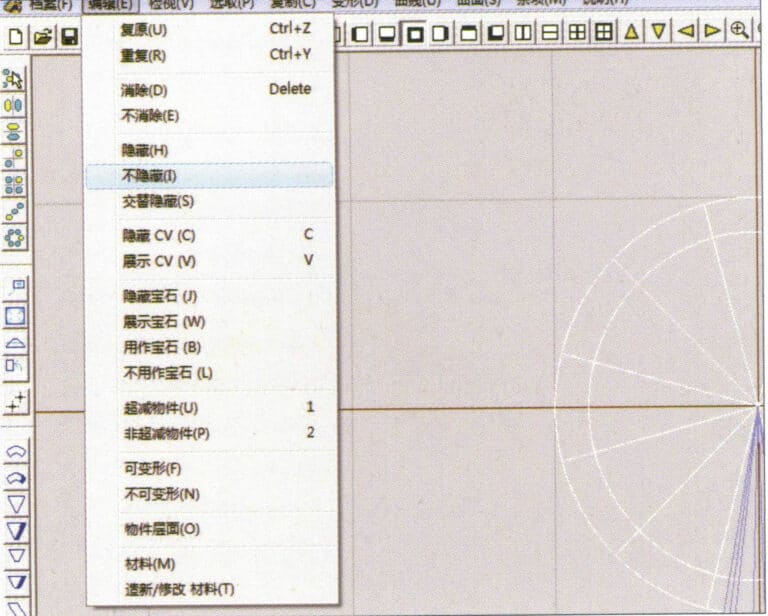
16. Select "View" > "Shadow Map" from the menu bar to inspect the shadow effects

17. Select "Edit" > "Unhide" from the menu bar to display the hidden circular surfaces
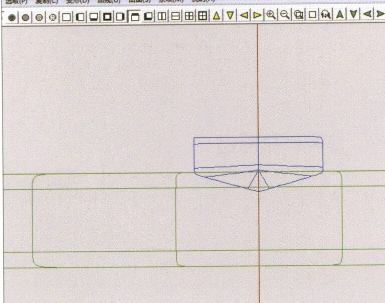
17. Select "Edit" > "Unhide" from the menu bar to display the hidden circular surfaces

18. Select "Deformation" > "Move" from the menu bar to move the selected surface
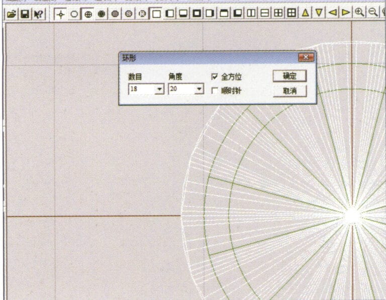
18. Select "Deformation" > "Move" from the menu bar to move the selected surface

19. Select "Copy" > "Circular Copy" from the menu bar, enter the relevant values and confirm

19. Select "Copy" > "Circular Copy" from the menu bar, enter the relevant values and confirm

20. Select “Miscellaneous” > “Boolean” > “Integrate” on the menu bar to integrate the selected surfaces.
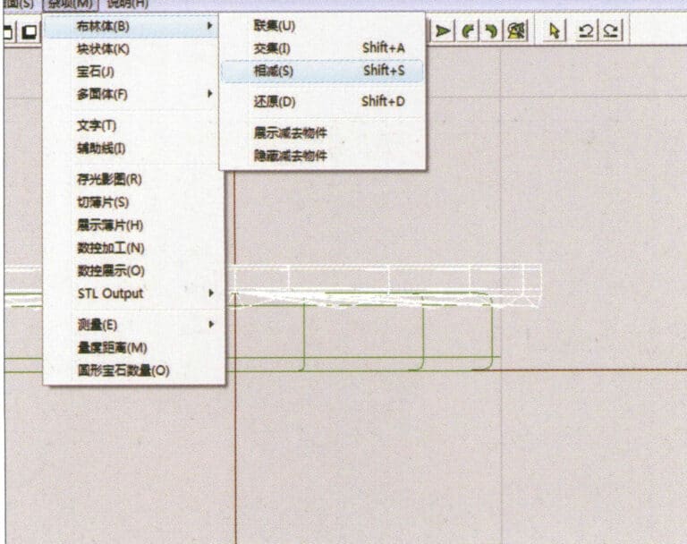
20. Select “Miscellaneous” > “Boolean” > “Integrate” on the menu bar to integrate the selected surfaces.

21. Select "Miscellaneous" > "Boolean" > "Subtract" from the menu bar to subtract the selected surface from the already united surface
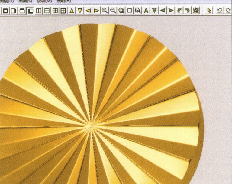
21. Select "Miscellaneous" > "Boolean" > "Subtract" from the menu bar to subtract the selected surface from the already united surface

22. Select "View" > "Shadow Map" from the menu bar to inspect the shadow effects. 23. Select "File" > "Save File" from the menu bar to save the document

22. Select "View" > "Shadow Map" from the menu bar to inspect the shadow effects.

23. Select "File" > "Save File" from the menu bar to save the document

Section III Using JewelCAD to Create Jewelry Effects

1. Diamond-Turned Setting Ring
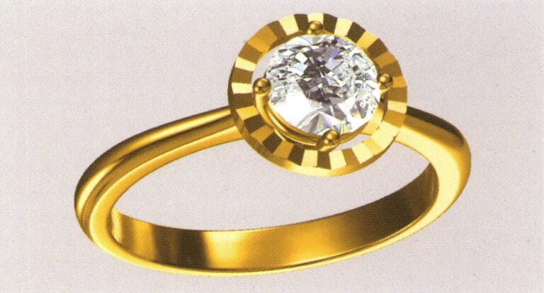
21

The steps for production are as follows:
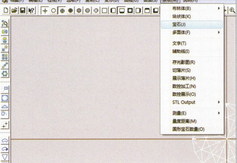
1. Create a new file in JewelCAD, select "Miscellaneous" > "Gem" from the menu bar

1. Create a new file in JewelCAD, select "Miscellaneous" > "Gem" from the menu bar

2. Select "Deformation" > "Multiple Deformation" from the menu bar
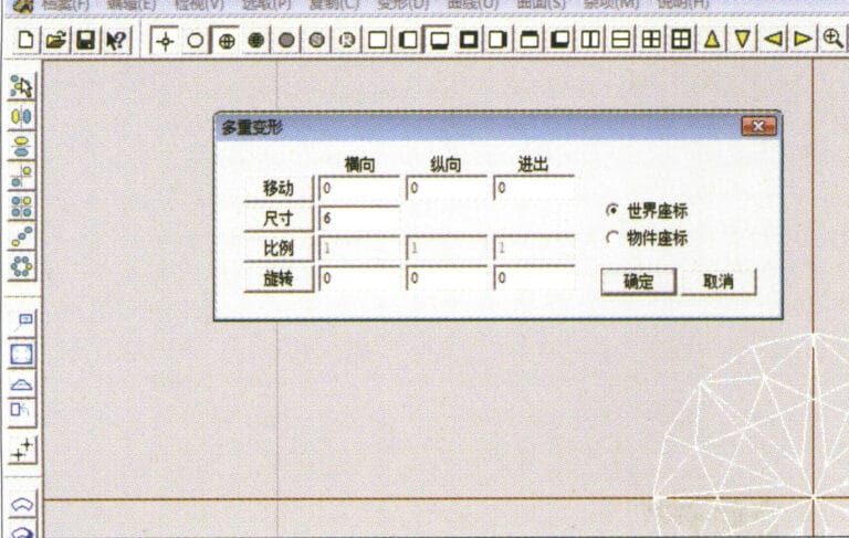
2. Select "Deformation" > "Multiple Deformation" from the menu bar

3. Enter the "Multiple Deformation" dialog box, input the relevant values, and confirm
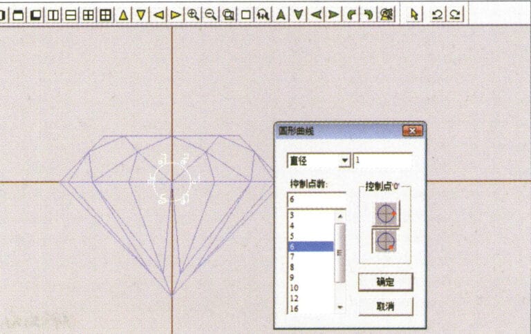
3. Enter the "Multiple Deformation" dialog box, input the relevant values, and confirm

4. Select “Curve” > “Circular Curve” in the menu bar to enter the “Circular Curve” dialog box, enter the relevant values and confirm
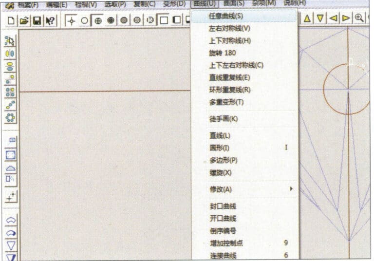
4. Select “Curve” > “Circular Curve” in the menu bar to enter the “Circular Curve” dialog box, enter the relevant values and confirm

5. Select "Curve" > "Freeform Curve" from the menu bar to draw a claw-shaped guideline
5. Select "Curve" > "Freeform Curve" from the menu bar to draw a claw-shaped guideline

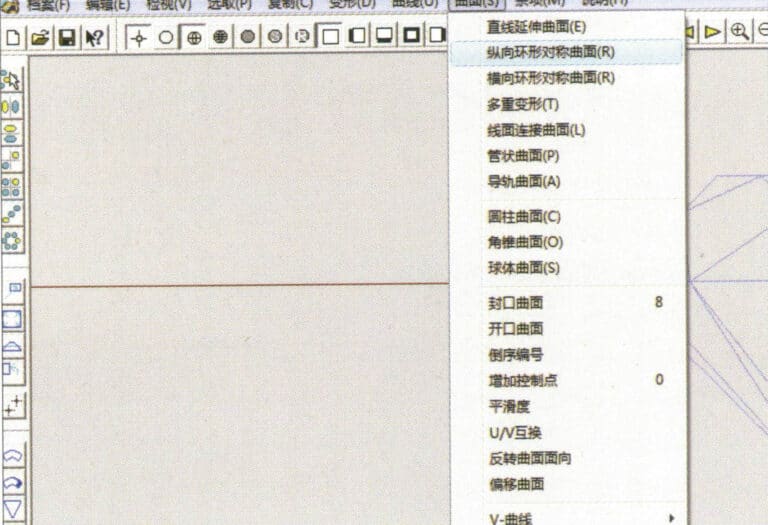
6. Select "Surface" > "Longitudinal Annular Symmetrical Surface" from the menu bar, and draw a claw shape
6. Select "Surface" > "Longitudinal Annular Symmetrical Surface" from the menu bar, and draw a claw shape

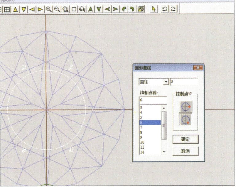
7. Select "Curve" > "Circular Curve" from the menu bar, enter the relevant values in the "Circular Curve" dialog box and confirm
7. Select "Curve" > "Circular Curve" from the menu bar, enter the relevant values in the "Circular Curve" dialog box and confirm

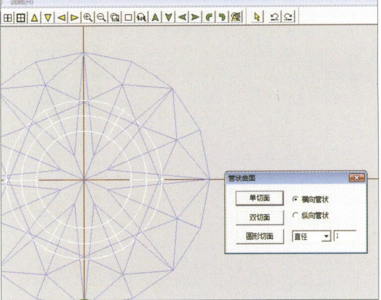
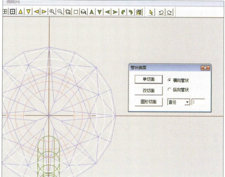
8. Select "Surface" > "Tubular Surface" from the menu bar, enter the relevant values and confirm
8. Select "Surface" > "Tubular Surface" from the menu bar, enter the relevant values and confirm

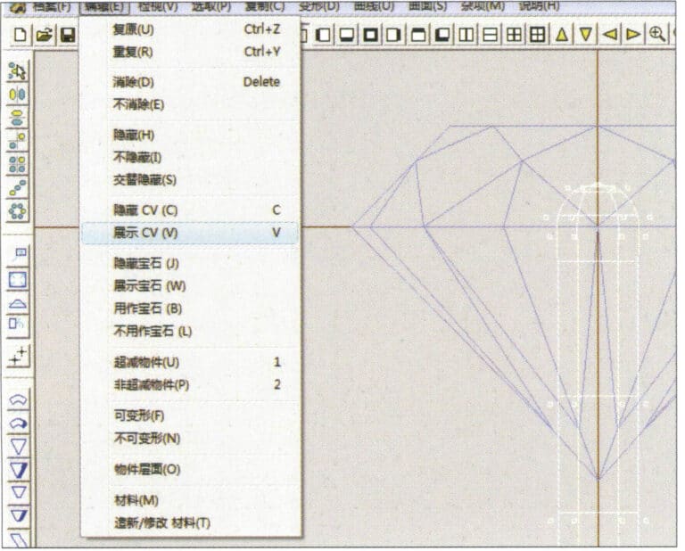
9. Select “Edit” > “Show CV” in the menu bar
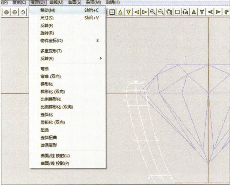
9. Select “Edit” > “Show CV” in the menu bar

10. Select “Deformation” > “Move” in the menu bar to move the CV
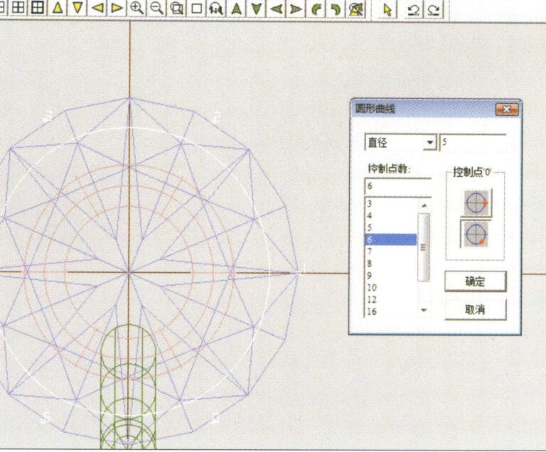
10. Select “Deformation” > “Move” in the menu bar to move the CV

11. Select "Curve" > "Circular Curve" from the menu bar, enter the relevant values in the "Circular Curve" dialog box and confirm
11. Select "Curve" > "Circular Curve" from the menu bar, enter the relevant values in the "Circular Curve" dialog box and confirm

12. Select "Surface" > "Tubular Surface" from the menu bar, enter the relevant values and confirm
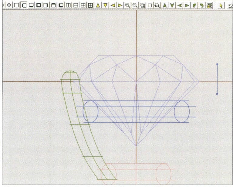
12. Select "Surface" > "Tubular Surface" from the menu bar, enter the relevant values and confirm

13. Select the menu bar "Edit" > "Move" to move the selected graphic

13. Select the menu bar "Edit" > "Move" to move the selected graphic

14. Select the completed claw shape, choose "Copy" > "Circular Copy" from the menu, enter the relevant values in the "Circular Copy" dialog box and confirm
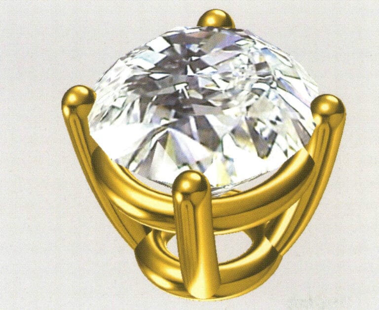
14. Select the completed claw shape, choose "Copy" > "Circular Copy" from the menu, enter the relevant values in the "Circular Copy" dialog box and confirm

15. Select "View" > "Shadow Map" from the menu bar to inspect the shadow effects
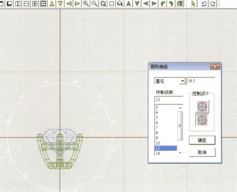
15. Select "View" > "Shadow Map" from the menu bar to inspect the shadow effects

16. Select "Curve" > "Circular Curve" from the menu bar, enter the "Circular Curve" dialog box, and input the relevant values as the inner diameter of the ring shank
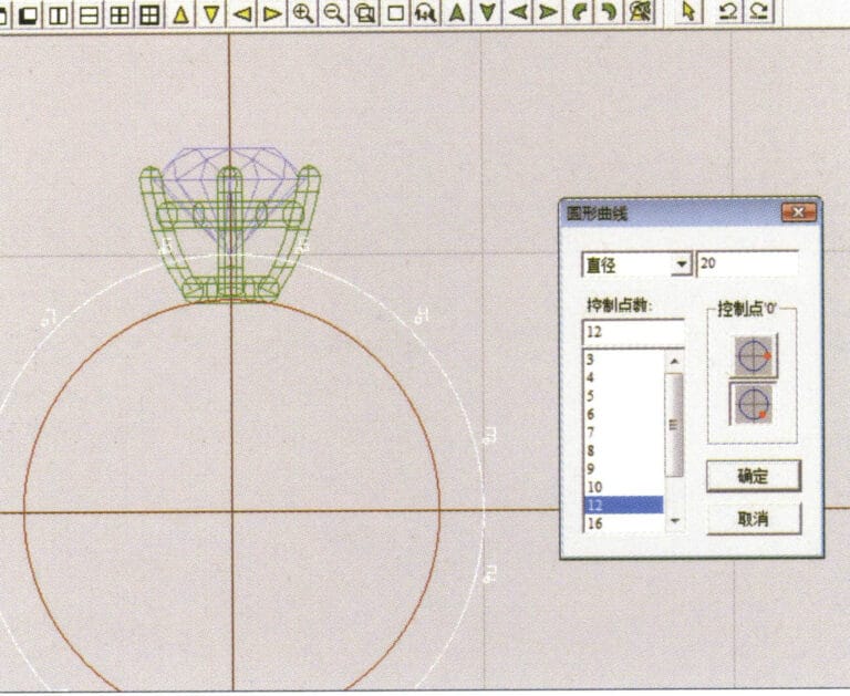
16. Select "Curve" > "Circular Curve" from the menu bar, enter the "Circular Curve" dialog box, and input the relevant values as the inner diameter of the ring shank

17. Select "Curve" > "Circular Curve" from the menu bar, enter the "Circular Curve" dialog box, and input the relevant values as the outer diameter of the ring shank

17. Select "Curve" > "Circular Curve" from the menu bar, enter the "Circular Curve" dialog box, and input the relevant values as the outer diameter of the ring shank

18. Select "Curve" > "Circular Curve" from the menu bar, enter the "Circular Curve" dialog box, and input the relevant values as the outer diameter of the engine-turned band
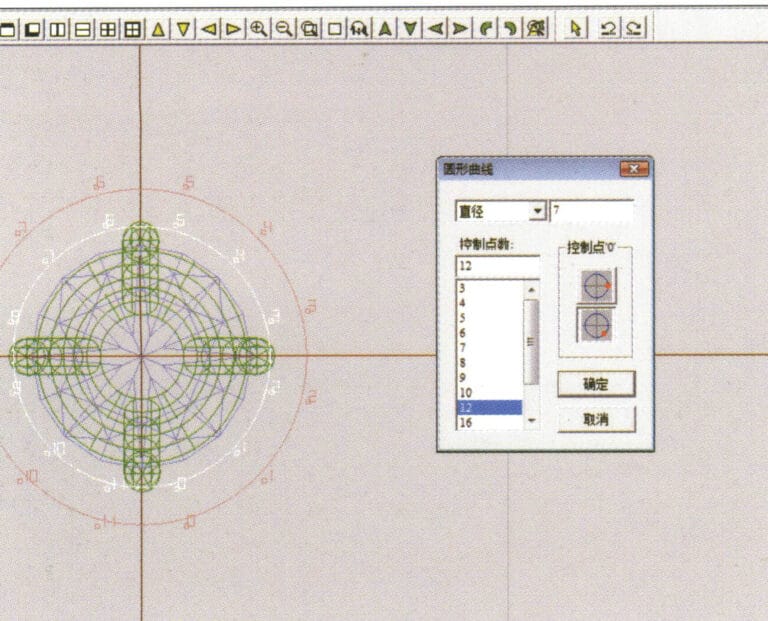
18. Select "Curve" > "Circular Curve" from the menu bar, enter the "Circular Curve" dialog box, and input the relevant values as the outer diameter of the engine-turned band

19. Select "Curve" > "Circular Curve" from the menu bar, enter the "Circular Curve" dialog box, and input the relevant values as the inner diameter of the engine-turned band
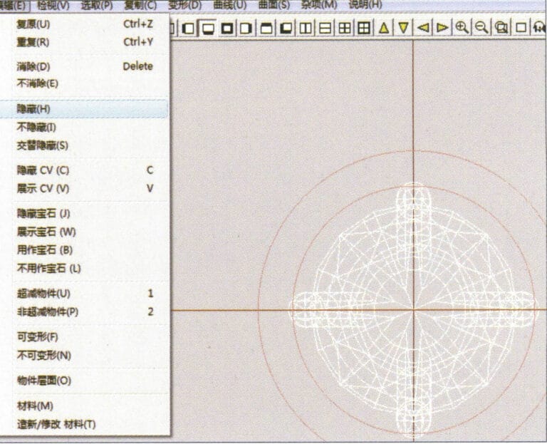
19. Select "Curve" > "Circular Curve" from the menu bar, enter the "Circular Curve" dialog box, and input the relevant values as the inner diameter of the engine-turned band

20. Select "Edit" > "Hide" from the menu bar to hide the completed gemstone inlay
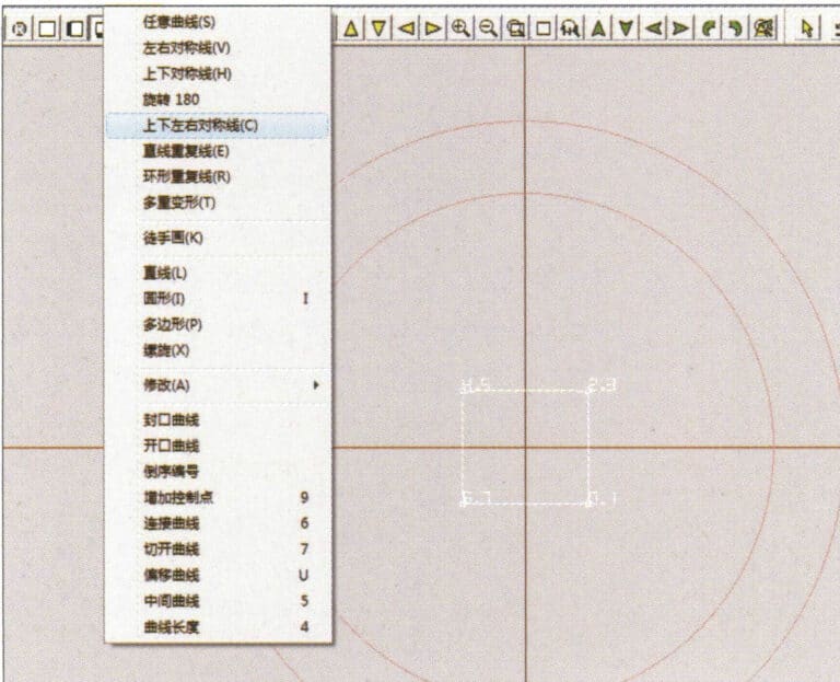
20. Select "Edit" > "Hide" from the menu bar to hide the completed gemstone inlay

21. Select "Curve" > "Vertical and Horizontal Symmetry Line" from the menu bar
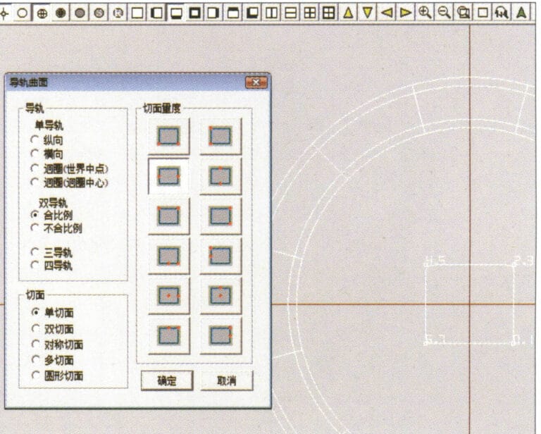
21. Select "Curve" > "Vertical and Horizontal Symmetry Line" from the menu bar

22. Select "Surface" > "Rail Surface" from the menu bar to enter the "Rail Surface" dialog box, select the relevant options and confirm
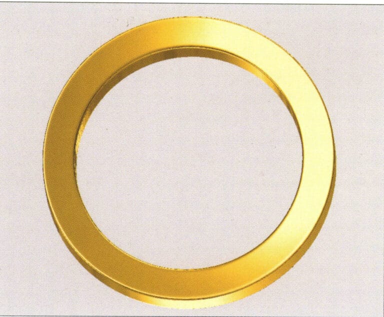
22. Select "Surface" > "Rail Surface" from the menu bar to enter the "Rail Surface" dialog box, select the relevant options and confirm

23. Select "View" > "Shadow Map" from the menu bar to inspect the shadow effects
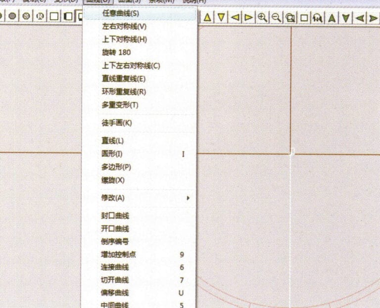
23. Select "View" > "Shadow Map" from the menu bar to inspect the shadow effects

24. Select "Curve" > "Freeform Curve" from the menu bar to draw a guideline

24. Select "Curve" > "Freeform Curve" from the menu bar to draw a guideline

25. Select "Copy" > "Hide Copy" from the menu bar to copy the already drawn auxiliary lines
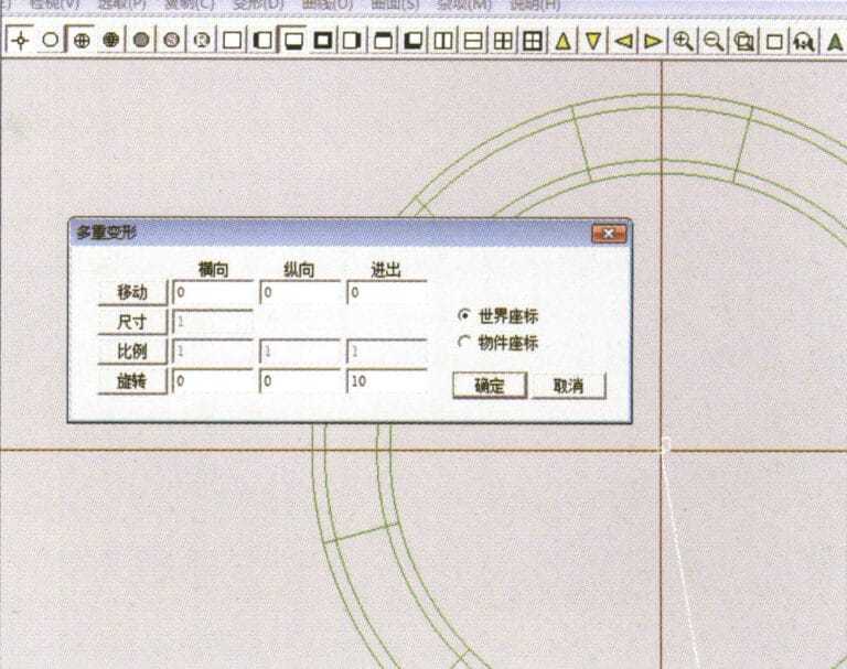
25. Select "Copy" > "Hide Copy" from the menu bar to copy the already drawn auxiliary lines

26. Select “Deformation” > “Multiple Deformation” in the menu bar to enter the “Multiple Deformation” dialog box, enter the relevant values and confirm
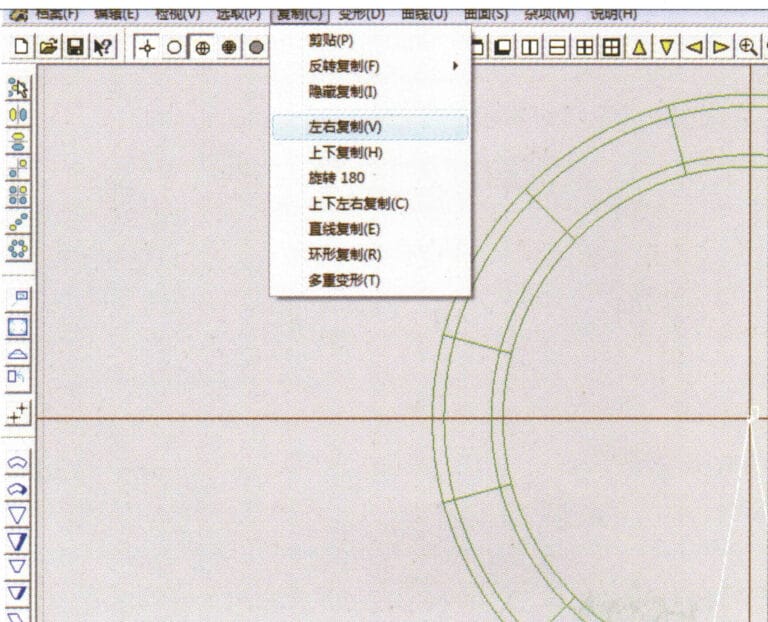
26. Select “Deformation” > “Multiple Deformation” in the menu bar to enter the “Multiple Deformation” dialog box, enter the relevant values and confirm

27. Select “Copy” > “Copy Up and Down” in the menu bar to copy the drawn auxiliary lines
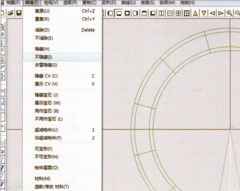
27. Select “Copy” > “Copy Up and Down” in the menu bar to copy the drawn auxiliary lines

28. Select "Edit" > "Unhide" from the menu to display the hidden curves
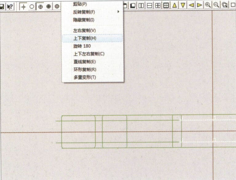
28. Select "Edit" > "Unhide" from the menu to display the hidden curves

29. Select "Copy" > "Copy Up and Down" from the menu bar to copy the selected curve
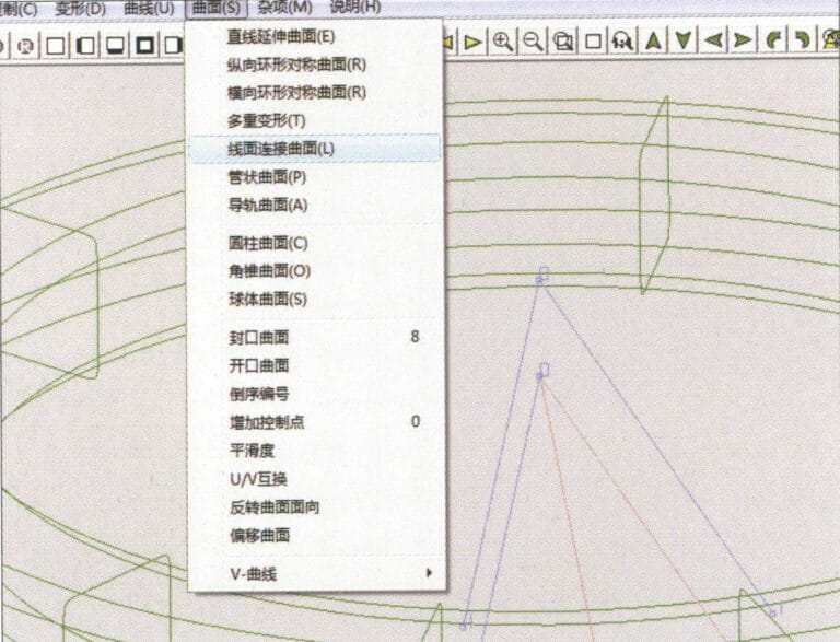
29. Select "Copy" > "Copy Up and Down" from the menu bar to copy the selected curve

30. Select curves/surfaces in a clockwise direction to create line-surface connections, then select "Surface" > "Cap Surface" from the menu bar
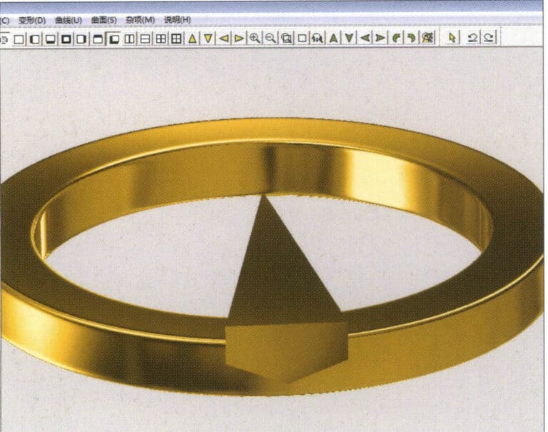
30. Select curves/surfaces in a clockwise direction to create line-surface connections, then select "Surface" > "Cap Surface" from the menu bar

31. Select "View" > "Shadow Map" from the menu bar to inspect the shadow effects
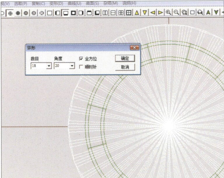
31. Select "View" > "Shadow Map" from the menu bar to inspect the shadow effects

32. Select "Copy" > "Circular Copy" from the menu bar, enter the relevant values and confirm
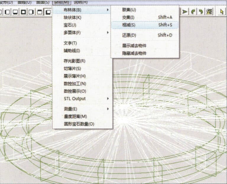
32. Select "Copy" > "Circular Copy" from the menu bar, enter the relevant values and confirm

33. Select "Miscellaneous" > "Boolean" > "Subtract" from the menu bar to subtract the selected surface from the already united surface
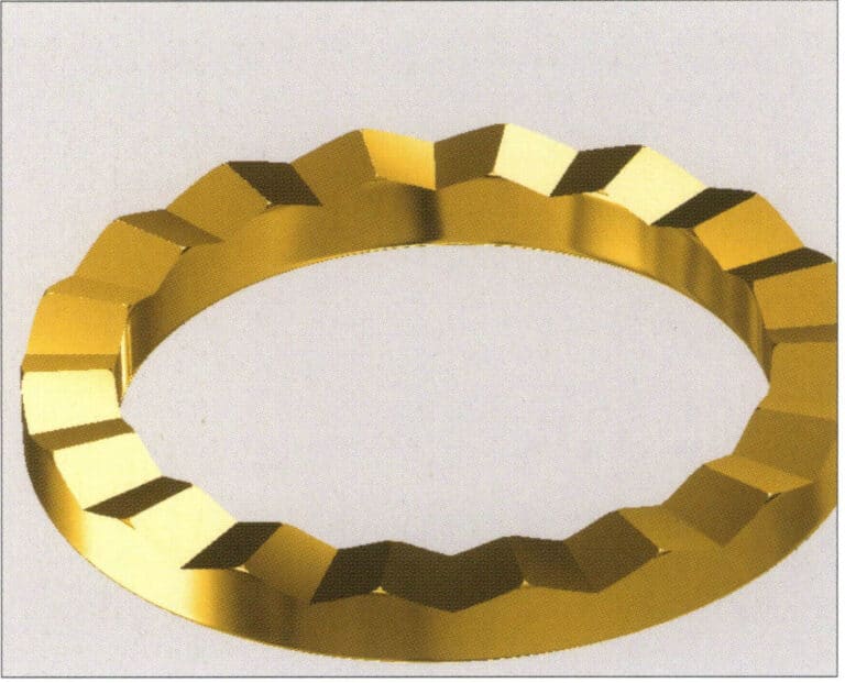
33. Select "Miscellaneous" > "Boolean" > "Subtract" from the menu bar to subtract the selected surface from the already united surface

34. Select "View" > "Shadow Map" from the menu bar to inspect the shadow effects
34. Select "View" > "Shadow Map" from the menu bar to inspect the shadow effects

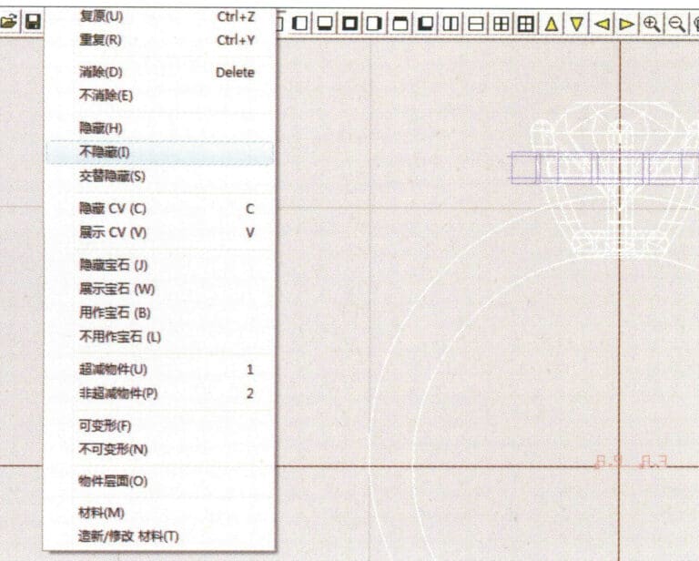
35. Select "Edit" > "Unhide" from the menu bar to display the hidden objects
35. Select "Edit" > "Unhide" from the menu bar to display the hidden objects

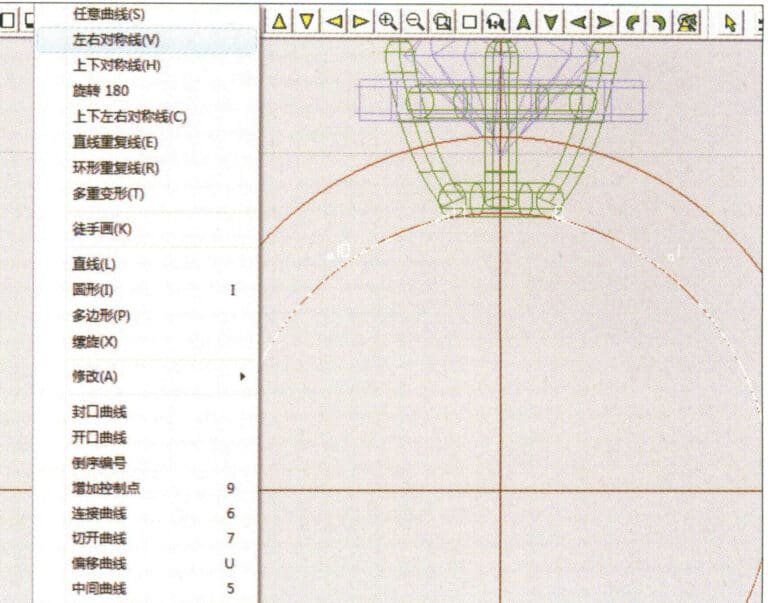
36. Select "Curve" > "Left-Right Symmetry Line" from the menu bar to draw the inner diameter of the ring wall
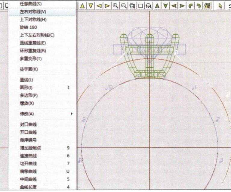
36. Select "Curve" > "Left-Right Symmetry Line" from the menu bar to draw the inner diameter of the ring wall

37. Select "Curve" > "Left-Right Symmetry Line" from the menu bar to draw the outer diameter of the ring wall
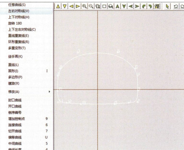
37. Select "Curve" > "Left-Right Symmetry Line" from the menu bar to draw the outer diameter of the ring wall

38. Select “Curve” > “Left-Right Symmetry Line” in the menu bar to draw a cutout of the ring shank
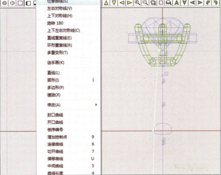
38. Select “Curve” > “Left-Right Symmetry Line” in the menu bar to draw a cutout of the ring shank

39. Select "Curve" > "Freeform Curve" from the menu bar to draw a guideline
39. Select "Curve" > "Freeform Curve" from the menu bar to draw a guideline

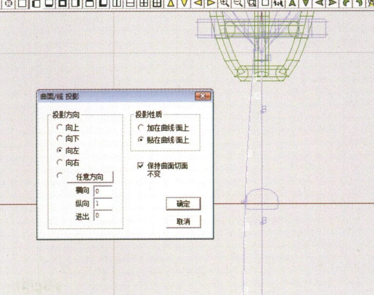
40. Select "Deformation" > "Surface/Line Projection" from the menu bar to enter the "Surface/Line Projection" dialog box, input the relevant values and confirm
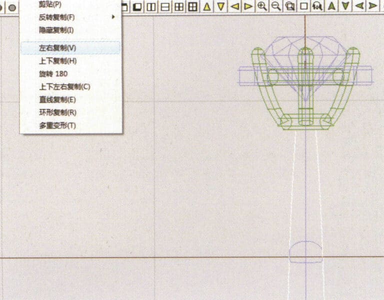
40. Select "Deformation" > "Surface/Line Projection" from the menu bar to enter the "Surface/Line Projection" dialog box, input the relevant values and confirm

41. Select "Copy" > "Copy Left and Right" from the menu bar to copy the inner diameter of the ring shank
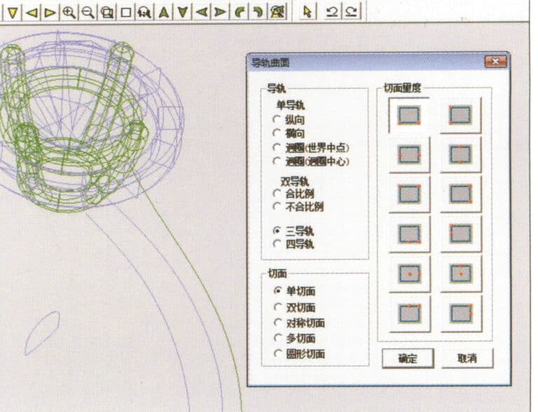
41. Select "Copy" > "Copy Left and Right" from the menu bar to copy the inner diameter of the ring shank

42. Select "Surface" > "Rail Surface" from the menu bar to enter the "Rail Surface" dialog box, select the relevant options and confirm
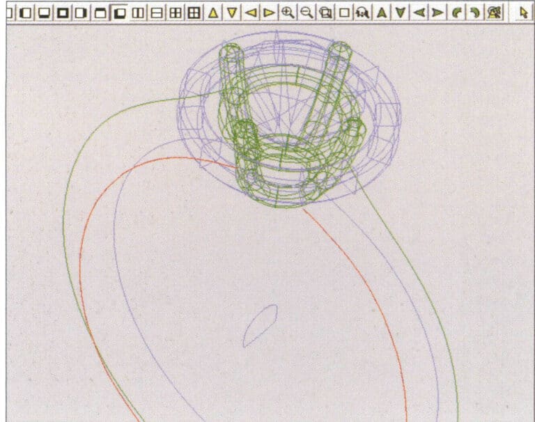
42. Select "Surface" > "Rail Surface" from the menu bar to enter the "Rail Surface" dialog box, select the relevant options and confirm

43. Select a curve as the left guide rail, and then select a curve as the right guide rail

43. Select a curve as the left guide rail, and then select a curve as the right guide rail

44. Select a curve as the upper guide rail
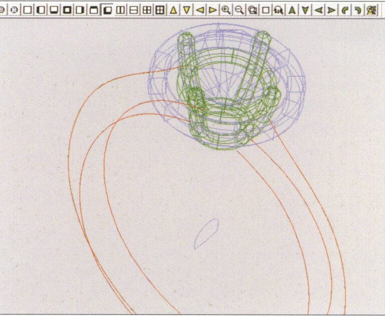
44. Select a curve as the upper guide rail

45. Select a curve as the cross-section of the guide surface.
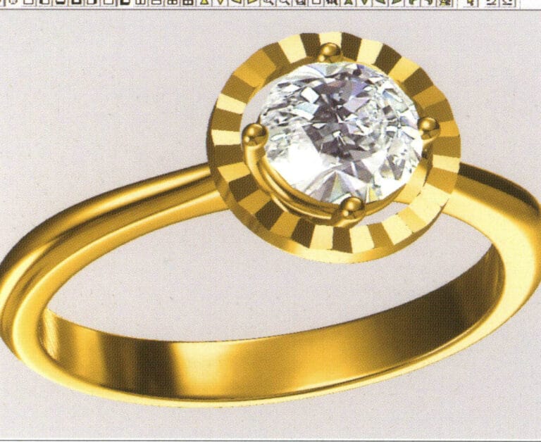
45. Select a curve as the cross-section of the guide surface.

46. Выберите "Вид" > "Карта света и тени" в строке меню, чтобы просмотреть эффекты света и тени 47. Выберите "Файл" > "Сохранить как" в строке меню, чтобы сохранить файл

46. Select "View" > "Light and Shadow Map" from the menu bar to examine the light and shadow effects

47. Select "File" > "Save As" from the menu bar to save the file

2. Pearl Ring

Pearl Ring

The steps for production are as follows:
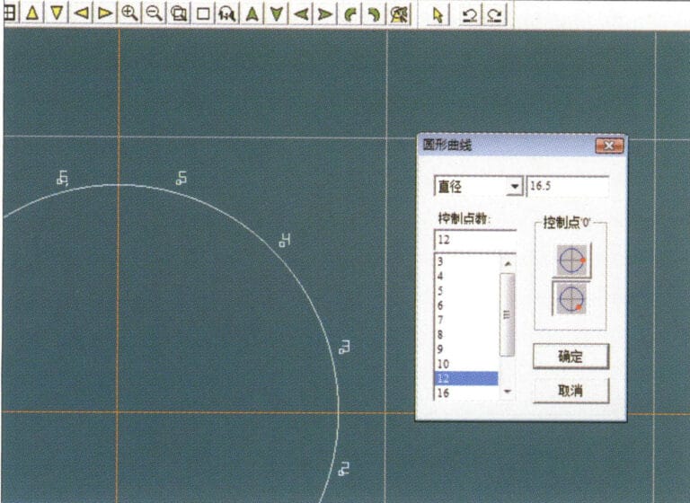
1. Create a new file in JewelCAD, select "Curve" > "Circular Curve" from the menu bar, enter the relevant values in the "Circular Curve" dialog box as the outer curve of the ring, and confirm
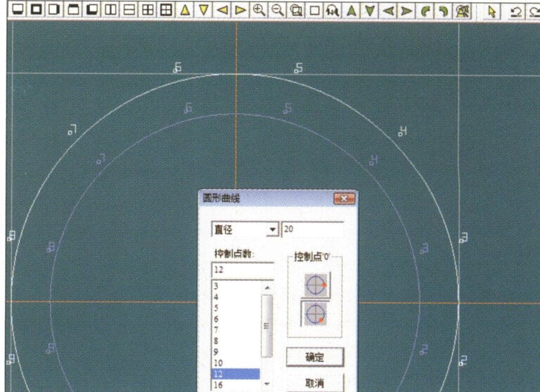
1. Create a new file in JewelCAD, select "Curve" > "Circular Curve" from the menu bar, enter the relevant values in the "Circular Curve" dialog box as the outer curve of the ring, and confirm

2. Select "Curve" > "Circular Curve" from the menu bar, enter the relevant values in the "Circular Curve" dialog box to set the inner curve of the ring, and confirm
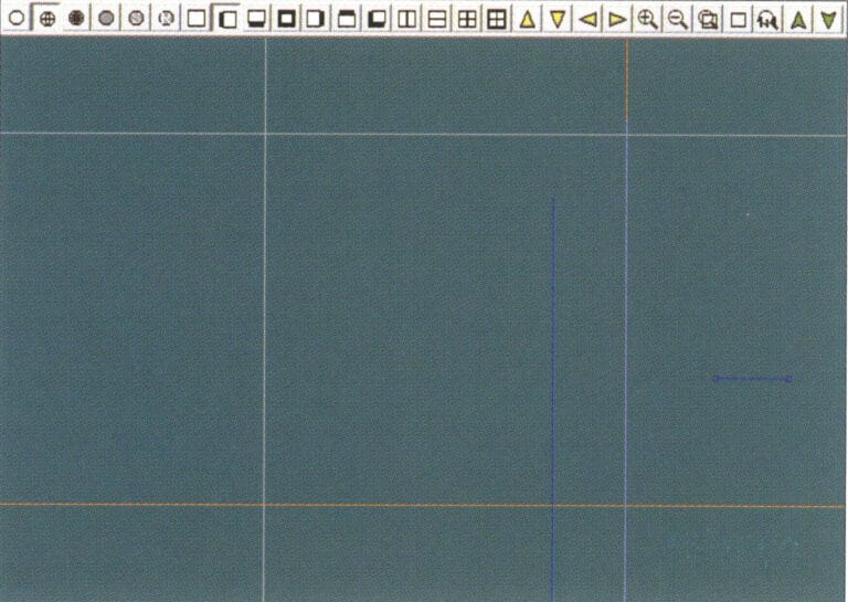
2. Select "Curve" > "Circular Curve" from the menu bar, enter the relevant values in the "Circular Curve" dialog box to set the inner curve of the ring, and confirm

3. Select "Edit" > "Move" from the menu bar to move the selected inner curve of the ring
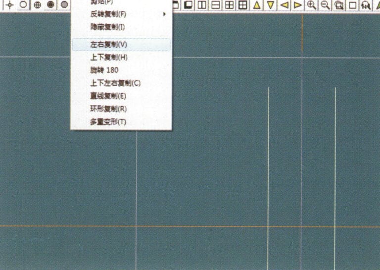
3. Select "Edit" > "Move" from the menu bar to move the selected inner curve of the ring

4. Select "Copy" > "Copy Left and Right" from the menu bar to copy the curve of the inner circle of the ring
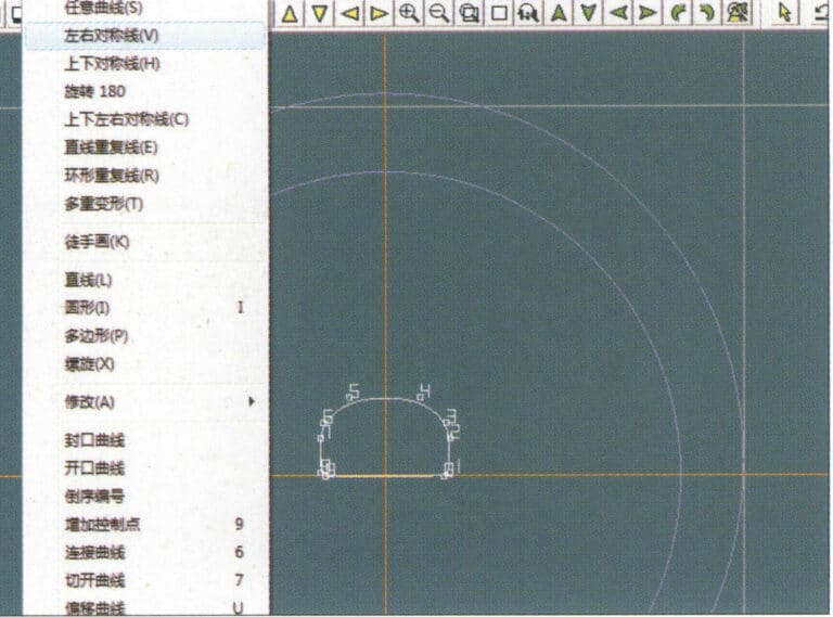
4. Select "Copy" > "Copy Left and Right" from the menu bar to copy the curve of the inner circle of the ring

5. Select "Curve" > "Left-Right Symmetry Line" from the menu bar as the cross-section of the ring band
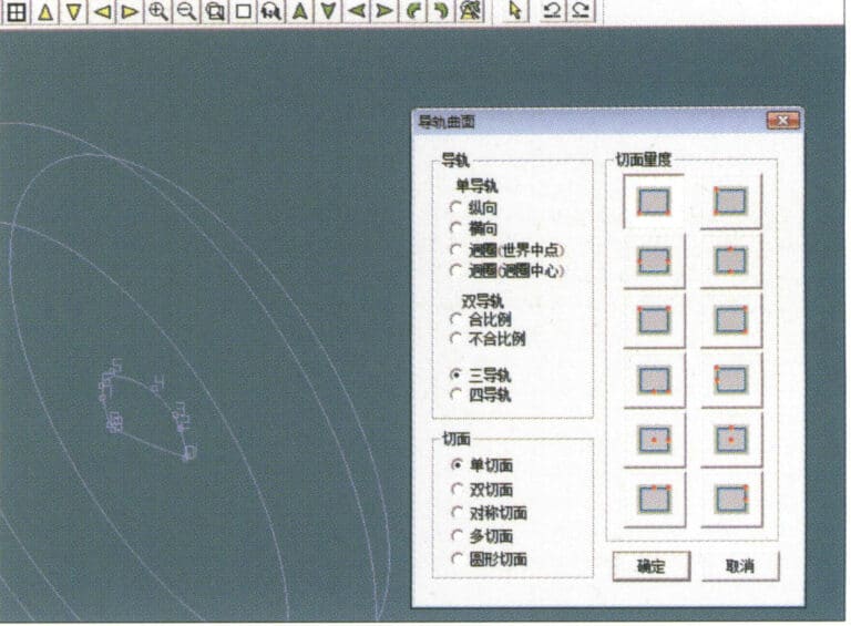
5. Select "Curve" > "Left-Right Symmetry Line" from the menu bar as the cross-section of the ring band

6. Select "Curved Surface" > "Guide Rail Surface" from the menu bar, enter the "Guide Rail Surface" dialog box, select the relevant options and confirm
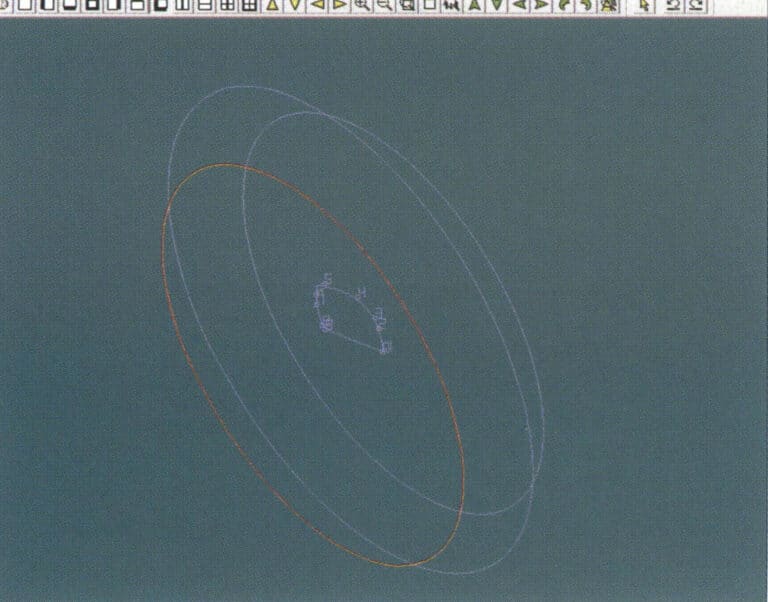
6. Select "Curved Surface" > "Guide Rail Surface" from the menu bar, enter the "Guide Rail Surface" dialog box, select the relevant options and confirm

7. Choose a curve as the right guide rail
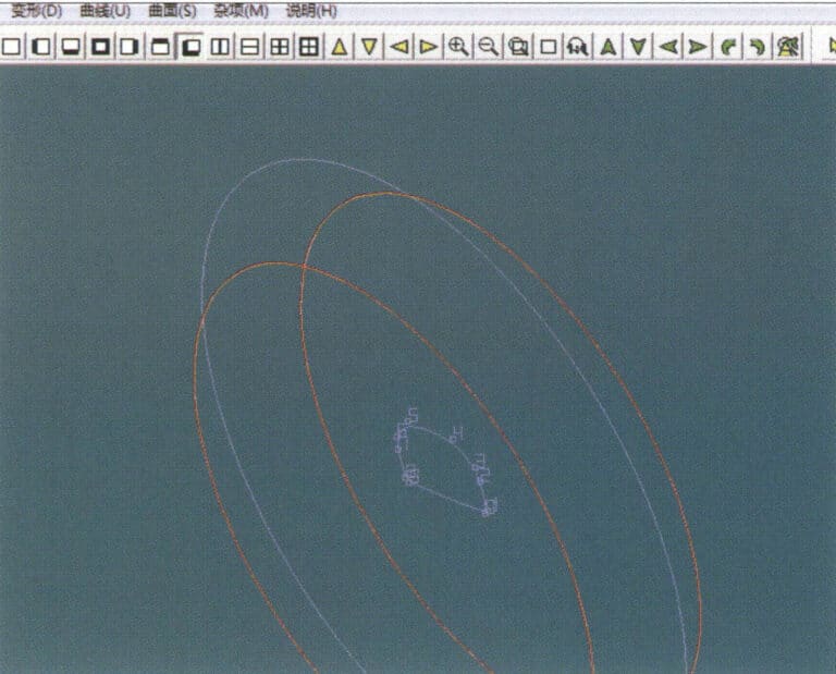
7. Choose a curve as the right guide rail

8. Choose a curve as the upper guide rail
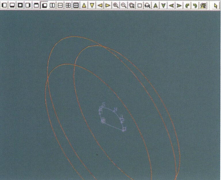
8. Choose a curve as the upper guide rail

9. Select the cross-section of the ring band as the cross-section of the guide curve surface
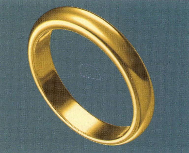
9. Select the cross-section of the ring band as the cross-section of the guide curve surface

10. Select "View" > "Shadow Map" from the menu bar to inspect the shadow effects
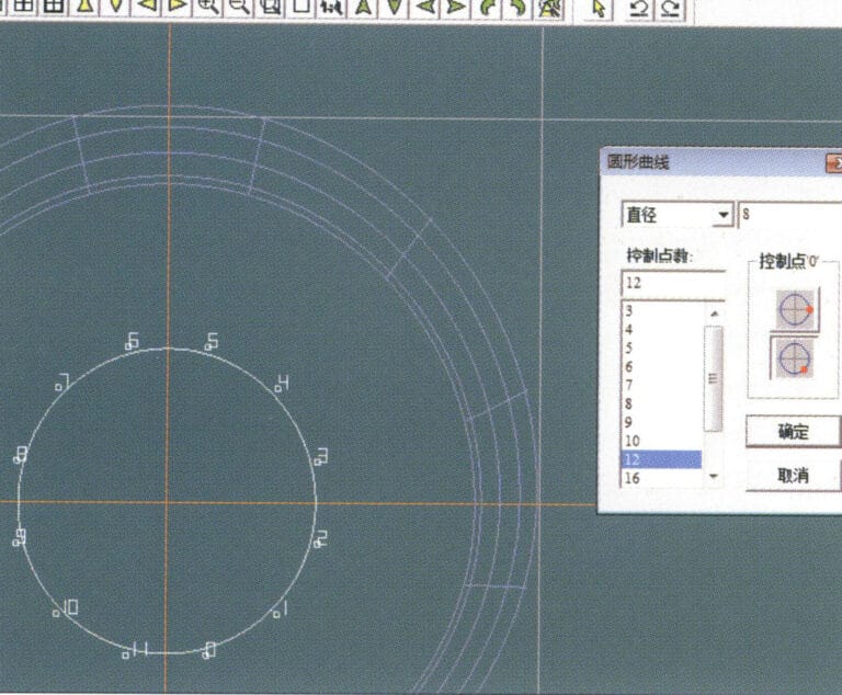
10. Select "View" > "Shadow Map" from the menu bar to inspect the shadow effects

11. Select "Curve" > "Circular Curve" from the menu bar, enter the relevant values in the "Circular Curve" dialog box as auxiliary lines, and confirm
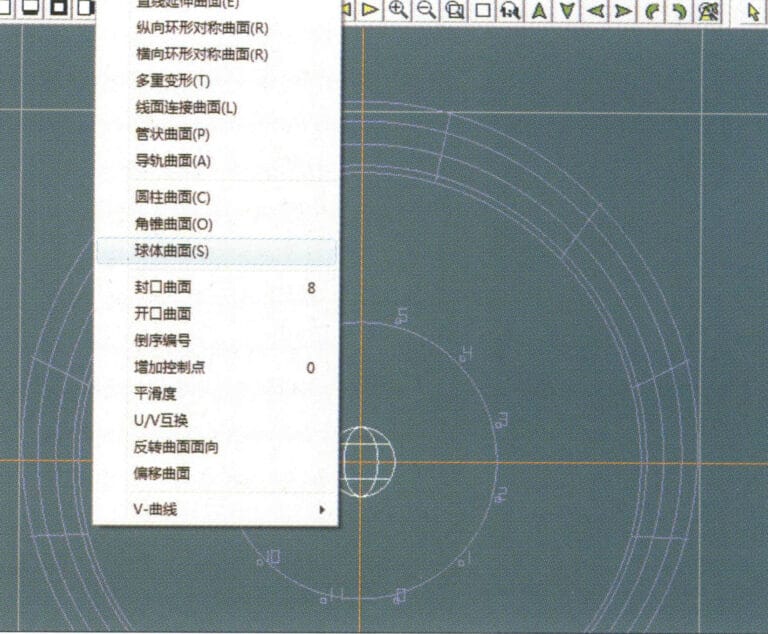
11. Select "Curve" > "Circular Curve" from the menu bar, enter the relevant values in the "Circular Curve" dialog box as auxiliary lines, and confirm

12. Select "Surface" > "Spherical Surface" from the menu bar
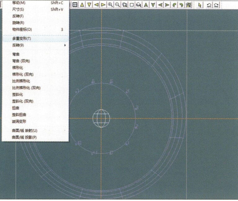
12. Select "Surface" > "Spherical Surface" from the menu bar

13. Select "Deformation" > "Multiple Deformation" from the menu bar to enlarge the sphere
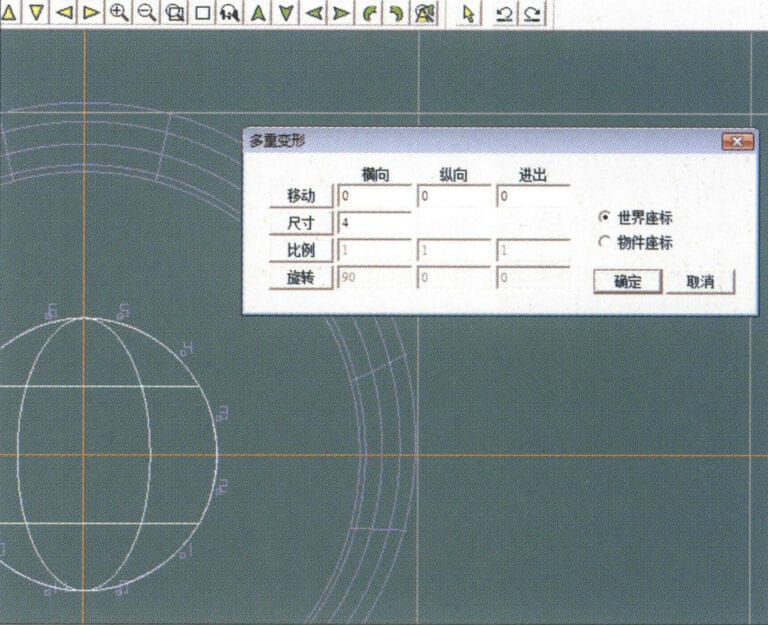
13. Select "Deformation" > "Multiple Deformation" from the menu bar to enlarge the sphere

14. Enter the "Multiple Deformation" dialog box, input the corresponding values to enlarge the sphere to the width of the guidelines, and confirm
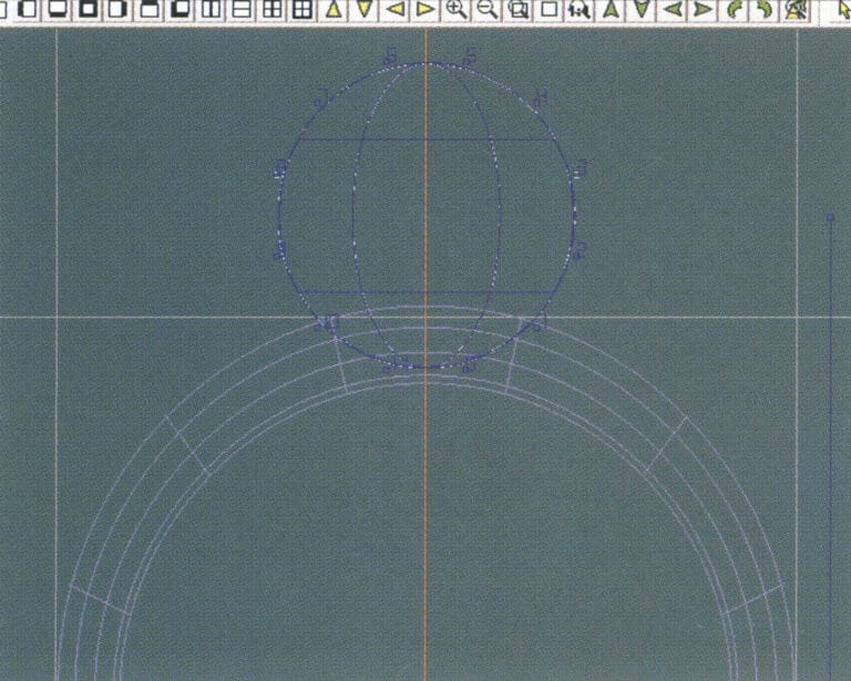
14. Enter the "Multiple Deformation" dialog box, input the corresponding values to enlarge the sphere to the width of the guidelines, and confirm

15. Select "Edit" > "Move" from the menu bar to move both the sphere and the auxiliary line simultaneously
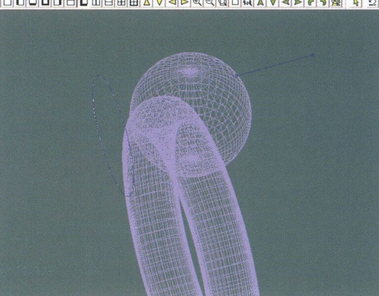
15. Select "Edit" > "Move" from the menu bar to move both the sphere and the auxiliary line simultaneously

16. Select "Edit" > "Move" from the menu bar to remove the guidelines
16. Select "Edit" > "Move" from the menu bar to remove the guidelines

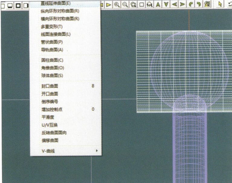
17. Select "Surface" > "Straight Line Extend Surface" from the menu bar to extend the auxiliary line into an auxiliary surface
17. Select "Surface" > "Straight Line Extend Surface" from the menu bar to extend the auxiliary line into an auxiliary surface

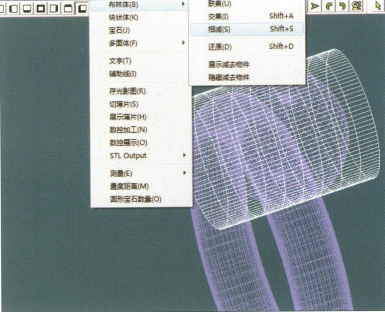
18. Select "Miscellaneous" > "Boolean" > "Subtract" from the menu bar to subtract the corresponding parts of the auxiliary surface ring
18. Select "Miscellaneous" > "Boolean" > "Subtract" from the menu bar to subtract the corresponding parts of the auxiliary surface ring

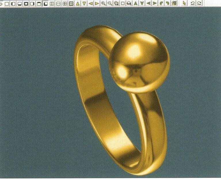
19. Select "View" > "Shadow Map" from the menu bar to inspect the shadow effects
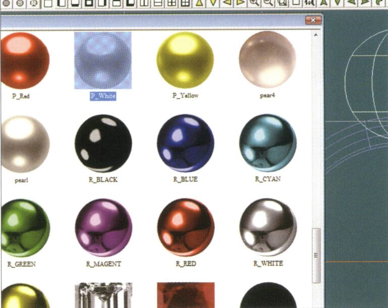
19. Select "View" > "Shadow Map" from the menu bar to inspect the shadow effects

20. Select the sphere, go to the menu bar and choose "Edit" > "Materials", enter the "Materials" dialog box, select the white pearl material and confirm
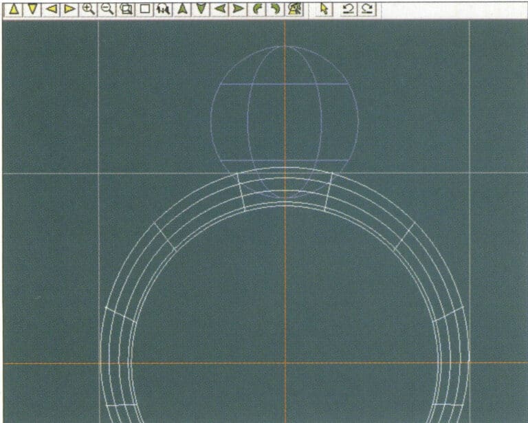
20. Select the sphere, go to the menu bar and choose "Edit" > "Materials", enter the "Materials" dialog box, select the white pearl material and confirm

21. Select the ring band, then choose "Edit" > "Materials" from the menu bar
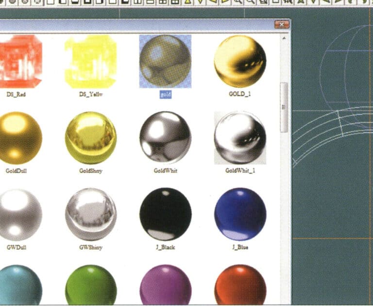
21. Select the ring band, then choose "Edit" > "Materials" from the menu bar

22. Enter the "Materials" dialog box, select the appropriate material, and confirm
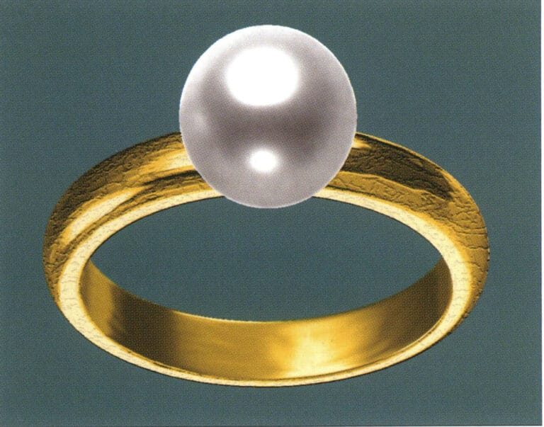
22. Enter the "Materials" dialog box, select the appropriate material, and confirm

23. Select "View" > "Shadow Map" from the menu bar to examine the light and shadow effects 24. Select "File" > "Save As" from the menu bar to save the file

23. Select "View" > "Shadow Map" from the menu bar to examine the light and shadow effects

24. Select "File" > "Save As" from the menu bar to save the file

3. Black Gold Pendant with Diamond Accents

Black Gold Pendant with Diamond Accents

The steps for production are as follows:
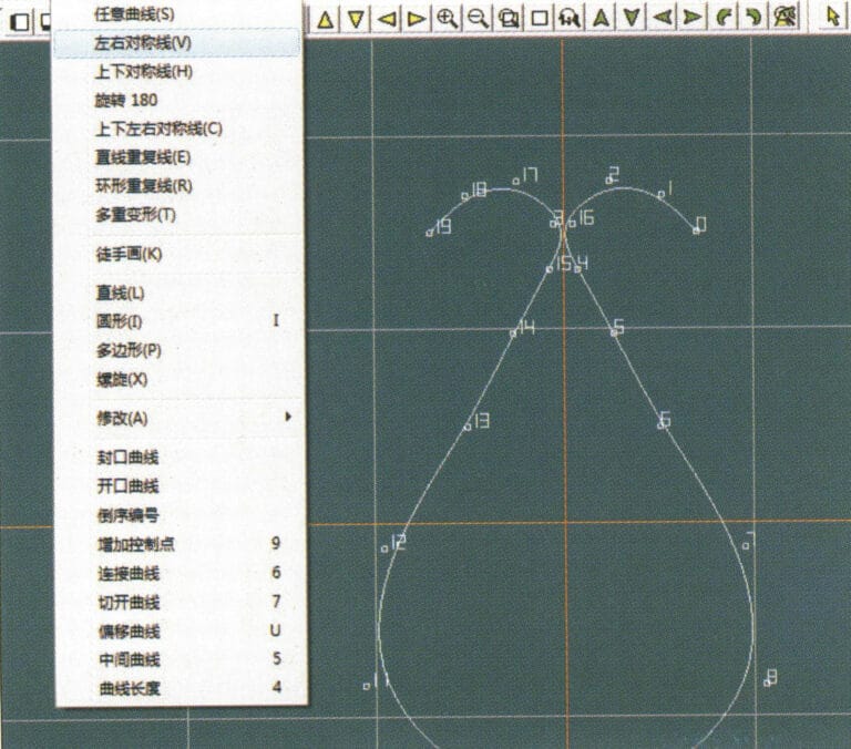
1. Create a new file in JewelCAD, select "Curve" > "Left-Right Symmetrical Line" from the menu bar, and draw the inner contour line of the pendant
1. Create a new file in JewelCAD, select "Curve" > "Left-Right Symmetrical Line" from the menu bar, and draw the inner contour line of the pendant

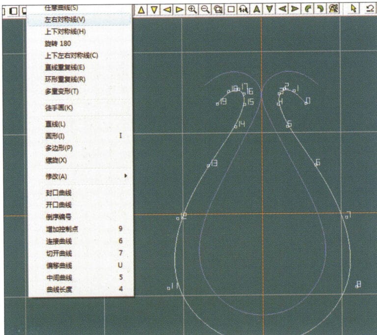
2. Select "Curve" > "Left-Right Symmetrical Line" from the menu bar to draw the outer contour line of the pendant (note that the control points of the inner contour line and the outer contour line should have the same direction and quantity).
2. Select "Curve" > "Left-Right Symmetrical Line" from the menu bar to draw the outer contour line of the pendant (note that the control points of the inner contour line and the outer contour line should have the same direction and quantity).

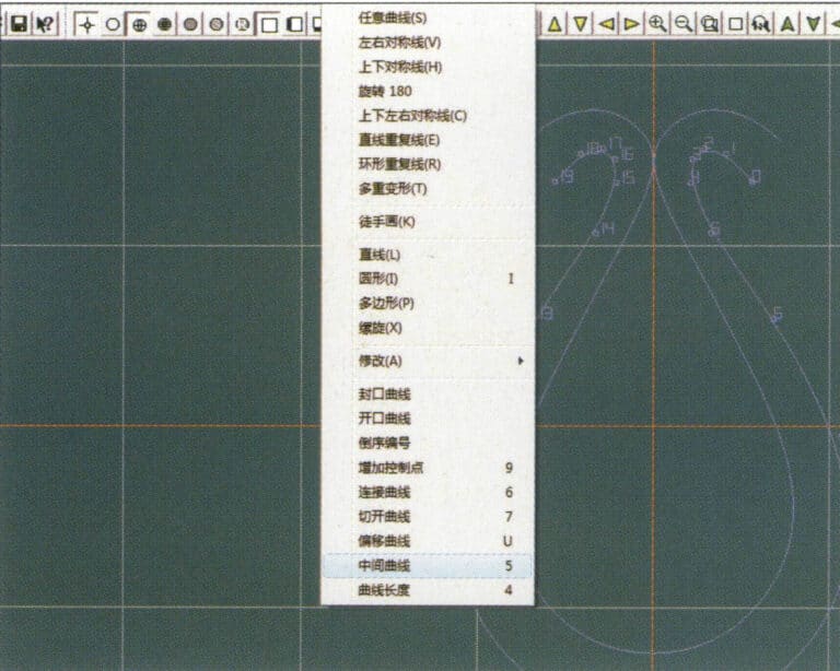
3. Select "Curve" > "Middle Curve" from the menu bar
3. Select "Curve" > "Middle Curve" from the menu bar

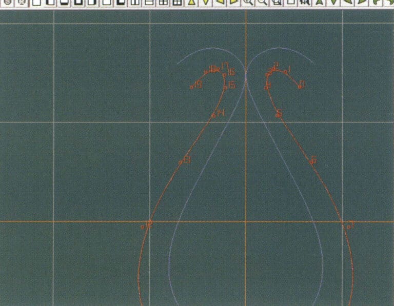
4. Select two curves to create the middle curve. First, select the outer contour line
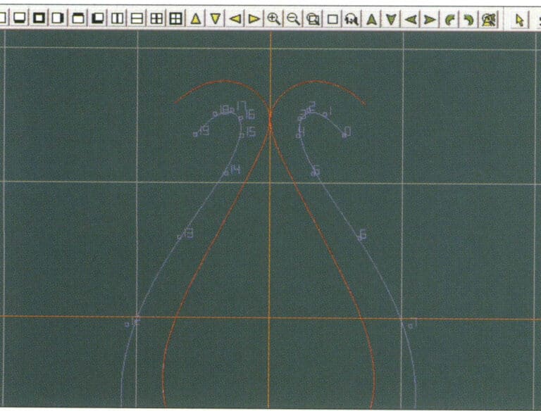
4. Select two curves to create the middle curve. First, select the outer contour line

5. Select two curves to create the middle curve, then select the inner contour line
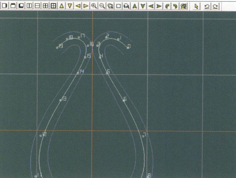
5. Select two curves to create the middle curve, then select the inner contour line

6. View the already created intermediate curves
6. View the already created intermediate curves

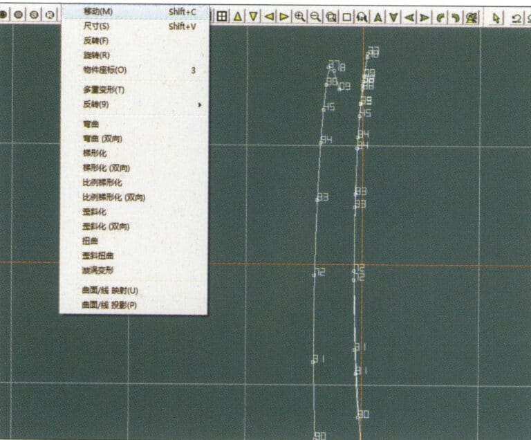
7. Select "Deformation" > "Move" from the menu bar to move the CV and the CV of the contour line
7. Select "Deformation" > "Move" from the menu bar to move the CV and the CV of the contour line

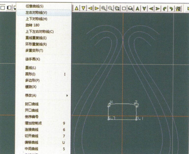
8. Select "Curve" > "Left-Right Symmetry Line" from the menu bar to create a cross-section
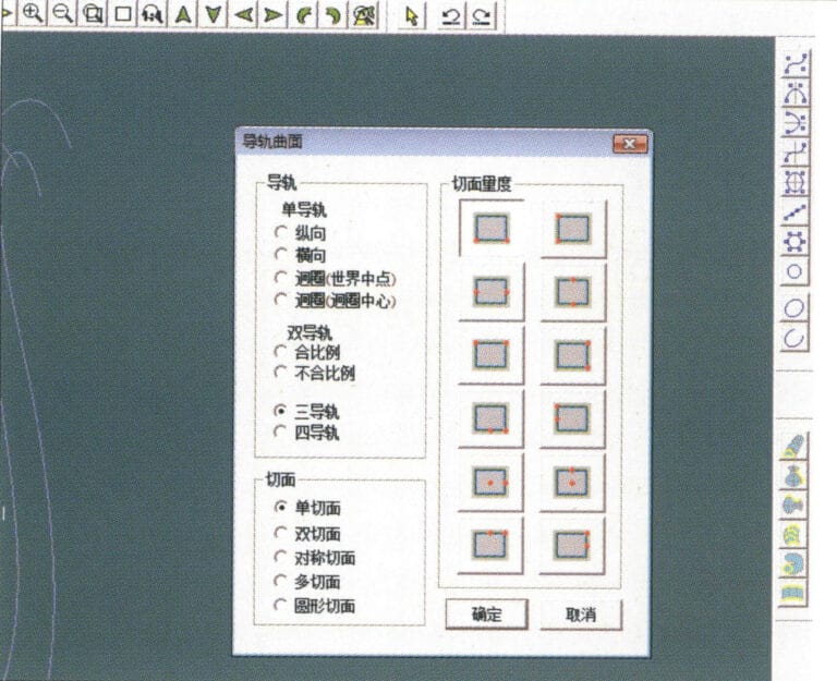
8. Select "Curve" > "Left-Right Symmetry Line" from the menu bar to create a cross-section

9. Select "Surface" > "Rail Surface" from the menu bar, enter the "Rail Surface" dialog box to select the relevant options, and confirm; select a curve as the left curve, starting from the left curve in a clockwise direction, left-click on the curve as the rail, and then select another curve as the section of the rail surface
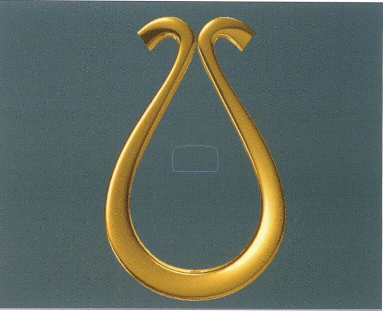
9. Select "Surface" > "Rail Surface" from the menu bar, enter the "Rail Surface" dialog box to select the relevant options, and confirm; select a curve as the left curve, starting from the left curve in a clockwise direction, left-click on the curve as the rail, and then select another curve as the section of the rail surface

10. Select "View" > "Shadow Map" from the menu bar to inspect the shadow effects
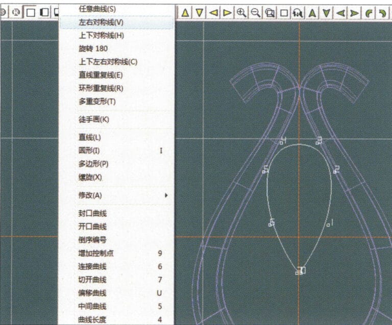
10. Select "View" > "Shadow Map" from the menu bar to inspect the shadow effects

11. Select "Curve" > "Left-Right Symmetry Line" from the menu bar to draw the outer contour line of the seed-shaped toggle
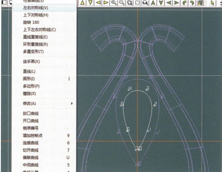
11. Select "Curve" > "Left-Right Symmetry Line" from the menu bar to draw the outer contour line of the seed-shaped toggle

12. Select "Curve" > "Left-Right Symmetry Line" from the menu bar to draw the inner contour line of the seed-shaped toggle
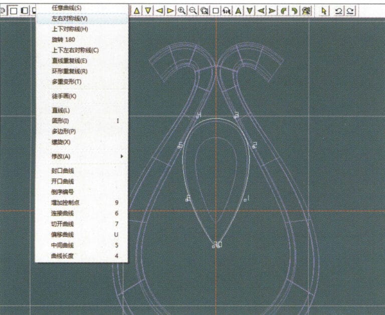
12. Select "Curve" > "Left-Right Symmetry Line" from the menu bar to draw the inner contour line of the seed-shaped toggle

13. Select "Curve" > "Left-Right Symmetry Line" from the menu bar, and draw the lower dark line of the center of the seed-shaped toggle
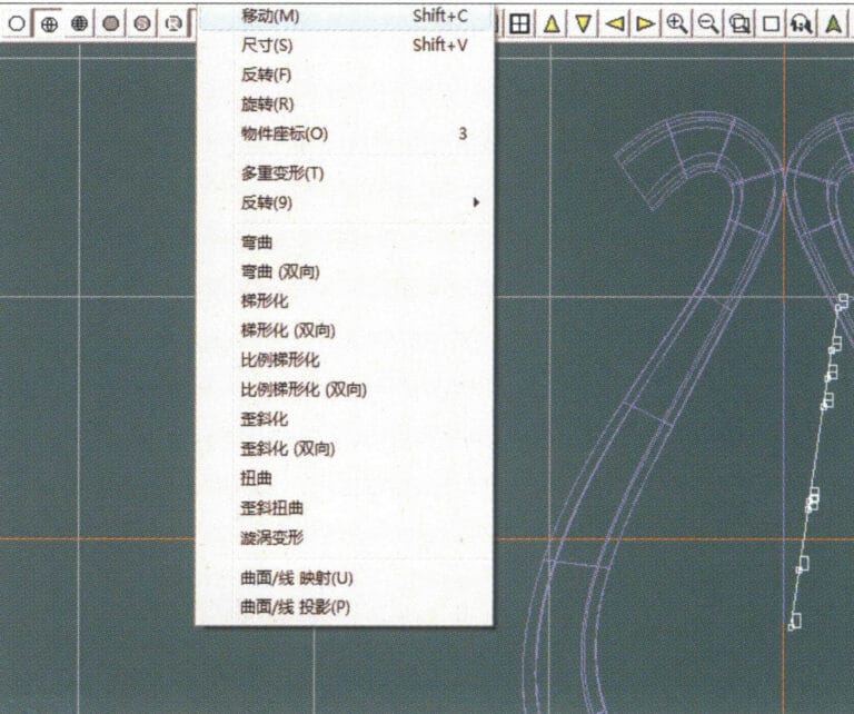
13. Select "Curve" > "Left-Right Symmetry Line" from the menu bar, and draw the lower dark line of the center of the seed-shaped toggle

14. Select "Deformation" > "Move" from the menu bar to move the seed-shaped toggle CV
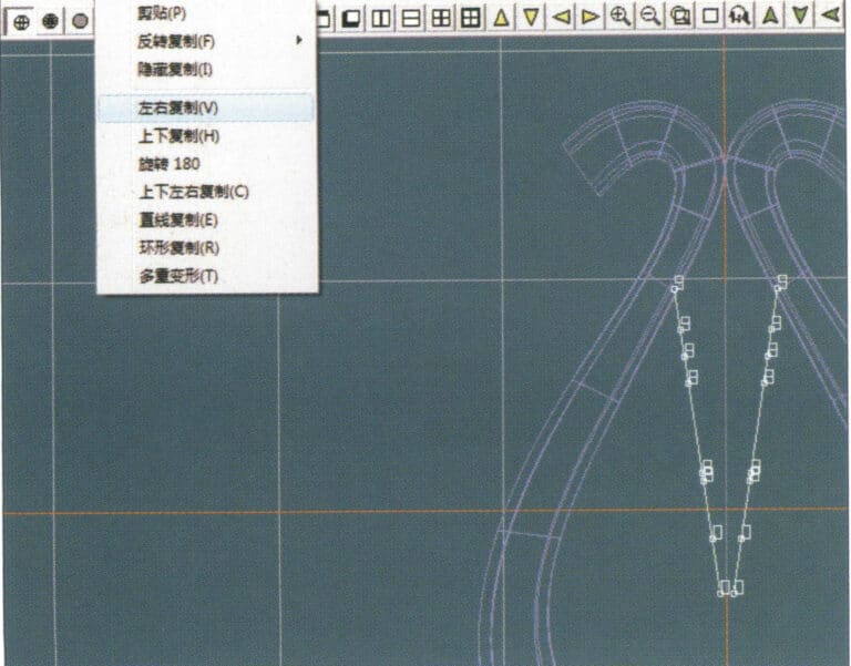
14. Select "Deformation" > "Move" from the menu bar to move the seed-shaped toggle CV

15. Select "Copy" > "Copy Left and Right" from the menu bar to copy the curve of the seed-shaped toggle
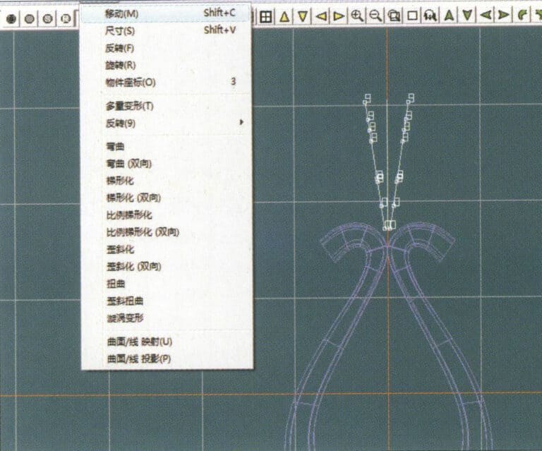
15. Select "Copy" > "Copy Left and Right" from the menu bar to copy the curve of the seed-shaped toggle

16. Select "Deformation" > "Move" from the menu bar to move the melon seed buckle curve
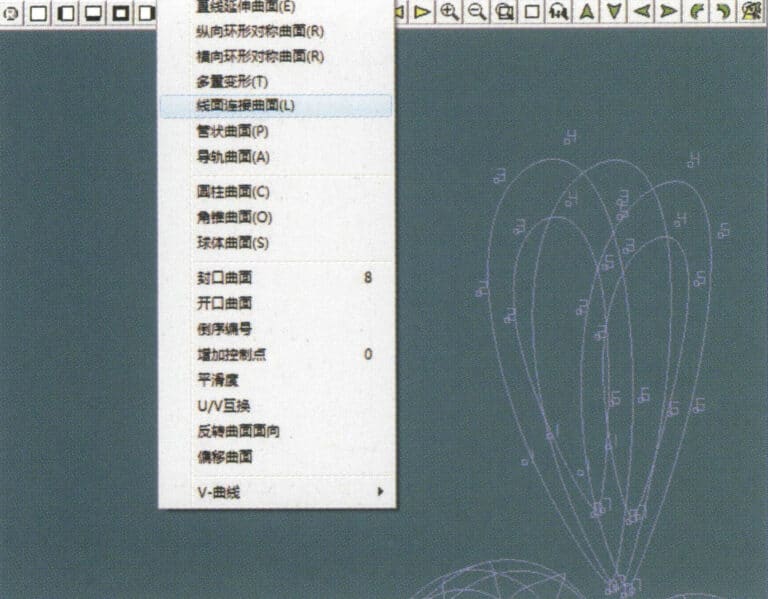
16. Select "Deformation" > "Move" from the menu bar to move the melon seed buckle curve

17. Select "Surface" > "Line-Surface Connection Surface" from the menu bar, and select the curve/surface in a clockwise direction to create a line-surface connection surface, then select "Curve" > "Closed Surface" from the menu bar
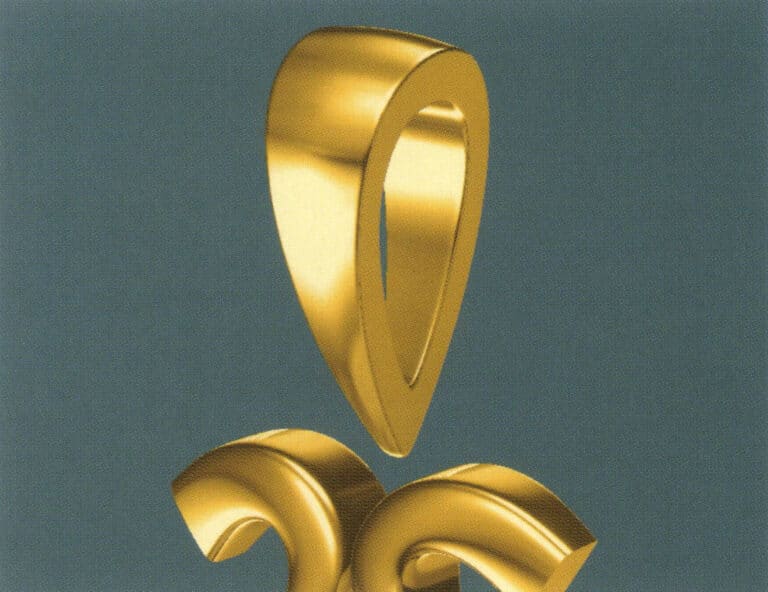
17. Select "Surface" > "Line-Surface Connection Surface" from the menu bar, and select the curve/surface in a clockwise direction to create a line-surface connection surface, then select "Curve" > "Closed Surface" from the menu bar

18. Select "View" > "Shadow Map" from the menu bar to examine the shadow effects
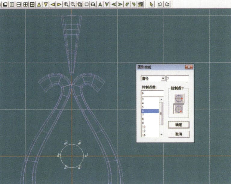
18. Select "View" > "Shadow Map" from the menu bar to examine the shadow effects

19. Select "Curve" > "Circular Curve" from the menu bar, enter the relevant values and confirm

19. Select "Curve" > "Circular Curve" from the menu bar, enter the relevant values and confirm

20. Select "Surface" > "Tubular Surface" from the menu bar
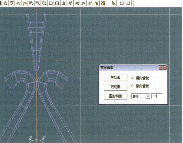
20. Select "Surface" > "Tubular Surface" from the menu bar

21. Enter the "Tubular Surface" dialog box, input the relevant values, click on the circular section, and confirm
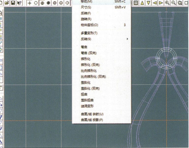
21. Enter the "Tubular Surface" dialog box, input the relevant values, click on the circular section, and confirm

22. Select "Deformation" > "Move" from the menu bar to move the ring buckle

22. Select "Deformation" > "Move" from the menu bar to move the ring buckle

23. Select "File" > "Insert File" from the menu bar
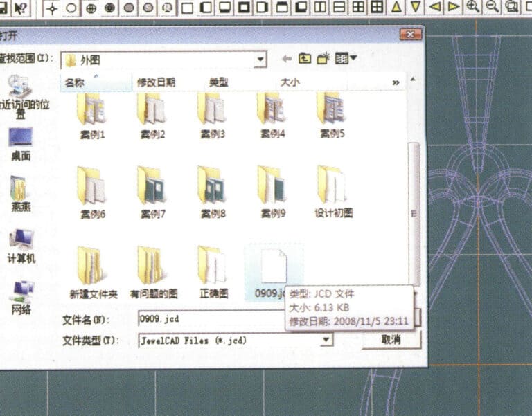
23. Select "File" > "Insert File" from the menu bar

24. Enter the "Insert File" dialog box, select the desired document and confirm
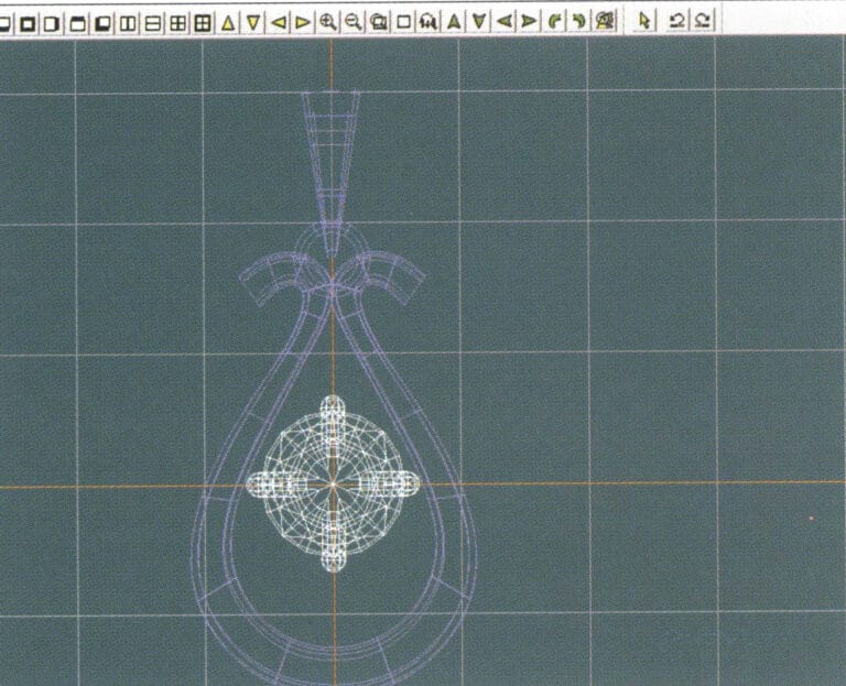
24. Enter the "Insert File" dialog box, select the desired document and confirm

25. View the inserted file - Gemstone
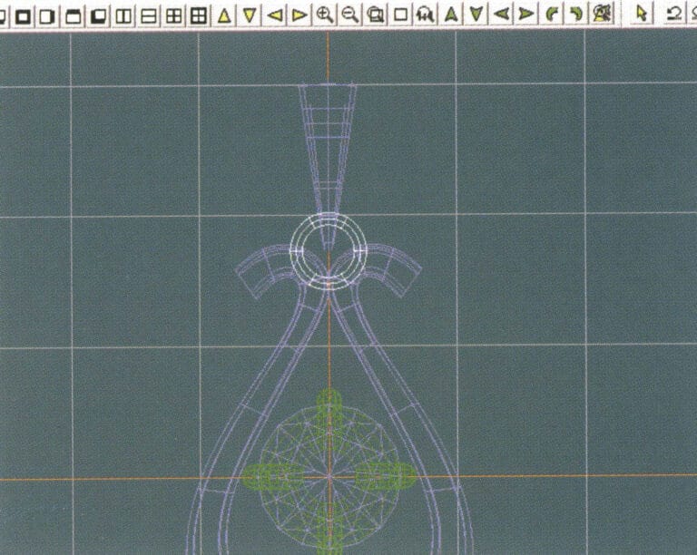
25. View the inserted file - Gemstone

26. Select "Copy" > "Copy Up and Down" from the menu bar to copy the selected toggle
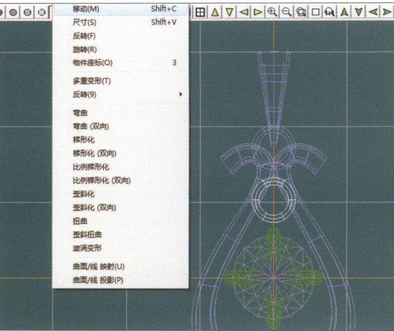
26. Select "Copy" > "Copy Up and Down" from the menu bar to copy the selected toggle

27. Select "Deformation" > "Move" from the menu bar to move the horizontal ring toggle
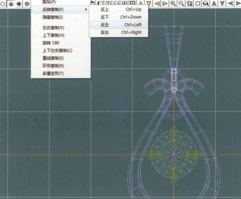
27. Select "Deformation" > "Move" from the menu bar to move the horizontal ring toggle

28. Select "Copy" > "Reverse Copy" > "Reverse Left" from the menu bar to create a vertical ring toggle
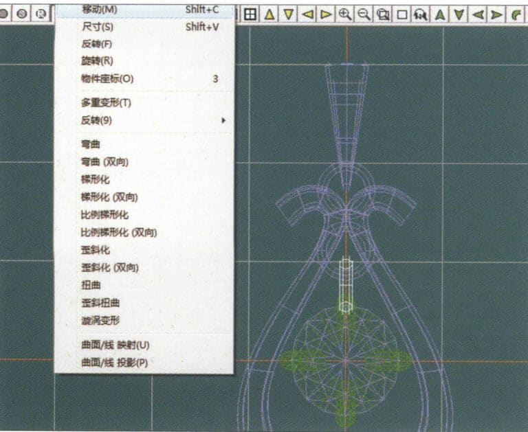
28. Select "Copy" > "Reverse Copy" > "Reverse Left" from the menu bar to create a vertical ring toggle

29. Select "Deformation" > "Move" from the menu bar to move the horizontal ring toggle
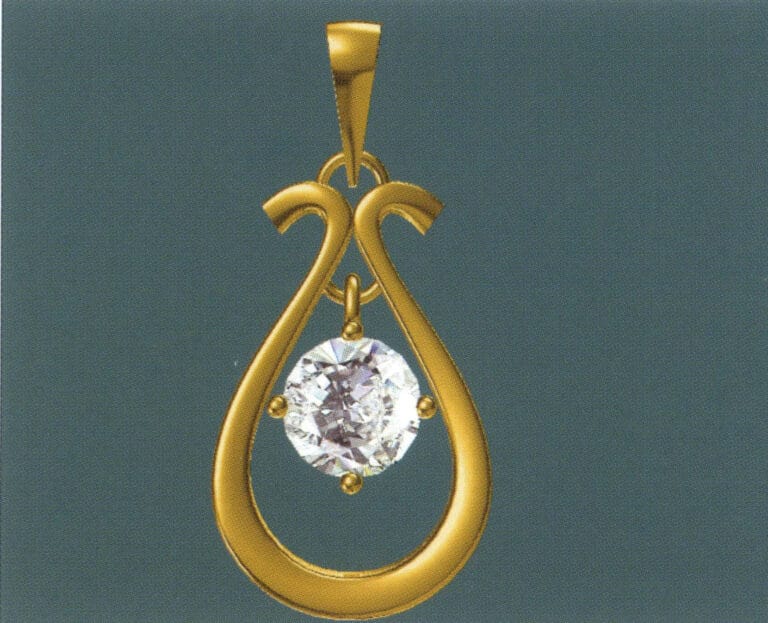
29. Select "Deformation" > "Move" from the menu bar to move the horizontal ring toggle

30. Select "View" > "Shadow Map" from the menu bar to examine the light and shadow effects
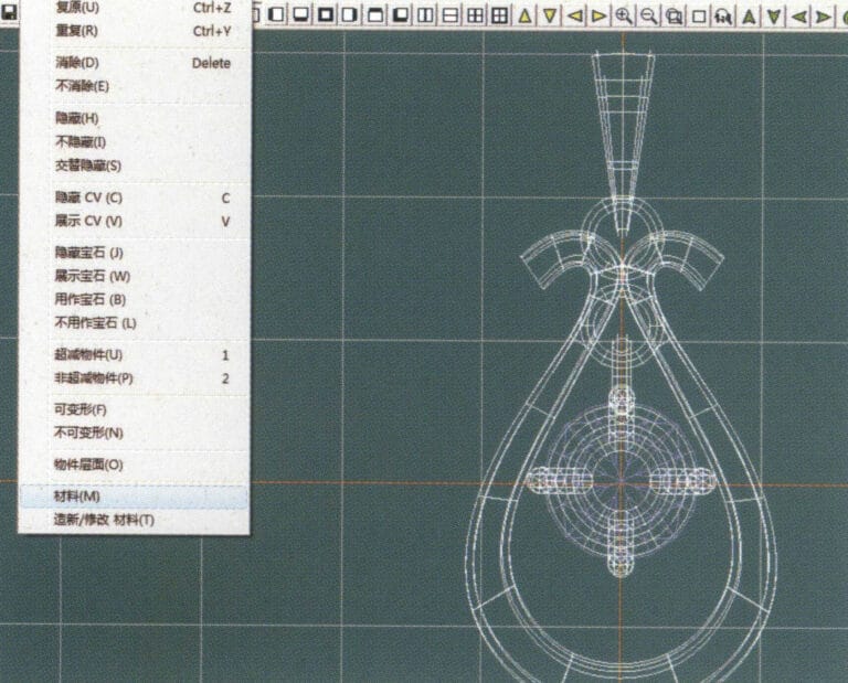
30. Select "View" > "Shadow Map" from the menu bar to examine the light and shadow effects

31. Select "Edit" > "Materials" from the menu bar to modify the materials of the selected object
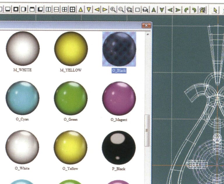
31. Select "Edit" > "Materials" from the menu bar to modify the materials of the selected object

32. Enter the "Materials" dialog box, select black gold and confirm
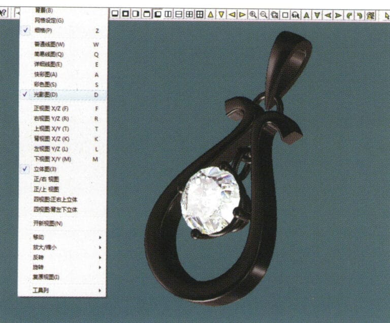
32. Enter the "Materials" dialog box, select black gold and confirm

33. Select "View" > "Shadow Map" from the menu bar to inspect the shadow effects 34. Select "File" > "Save As" from the menu bar to save the file

33. Select "View" > "Shadow Map" from the menu bar to inspect the shadow effects

34. Select "File" > "Save As" from the menu bar to save the file

4. Ruby Pendant
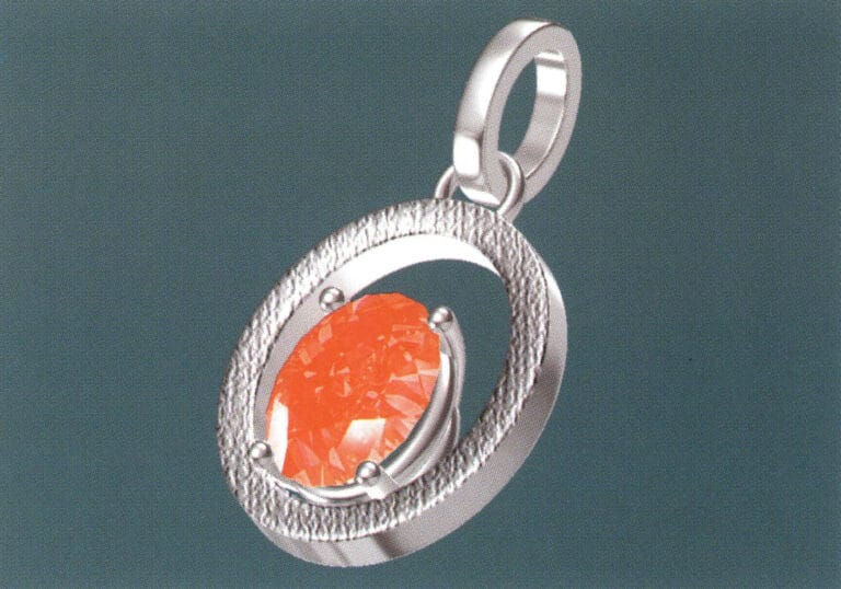
Ruby Pendant

The steps for production are as follows:
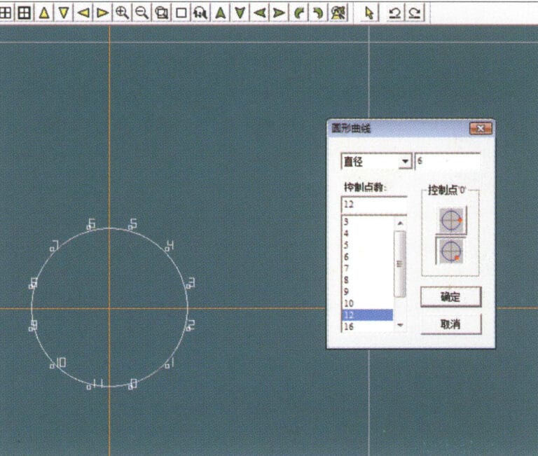
1. Create a new file in JewelCAD, select "Curve" > "Circular Curve" from the menu bar, enter the relevant values in the "Circular Curve" dialog box as the inner auxiliary line, and confirm

1. Create a new file in JewelCAD, select "Curve" > "Circular Curve" from the menu bar, enter the relevant values in the "Circular Curve" dialog box as the inner auxiliary line, and confirm

2. Select "Curve" > "Circular Curve" from the menu bar, enter the relevant values in the "Circular Curve" dialog box as the external auxiliary line, and confirm
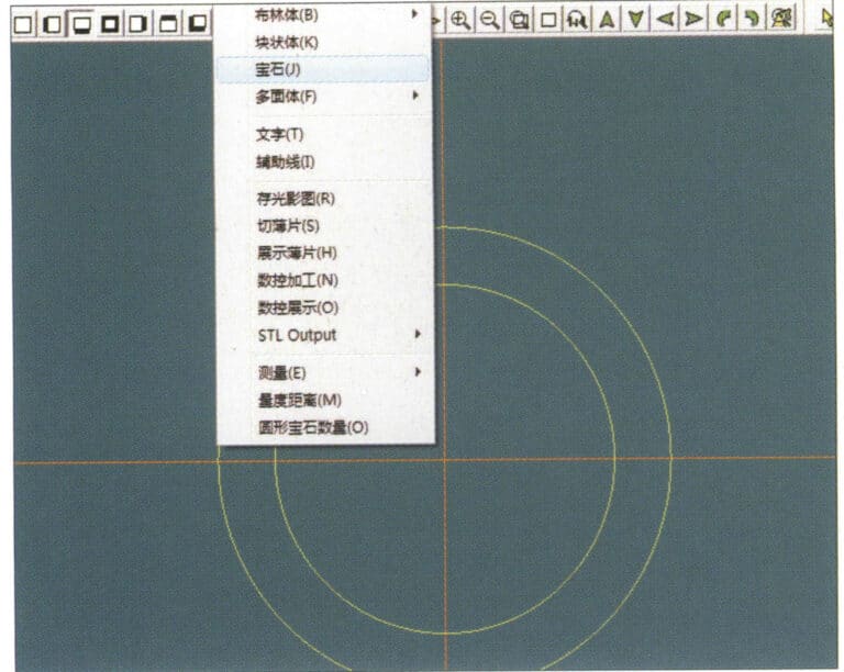
2. Select "Curve" > "Circular Curve" from the menu bar, enter the relevant values in the "Circular Curve" dialog box as the external auxiliary line, and confirm

3. Select "Miscellaneous" > "Gemstones" from the menu bar
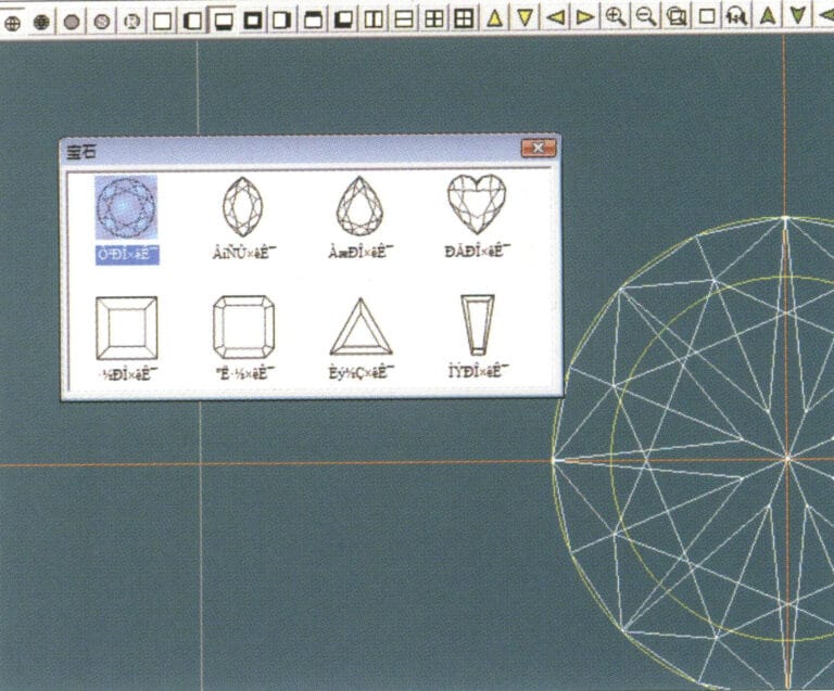
3. Select "Miscellaneous" > "Gemstones" from the menu bar

4. Enter the "Gem" dialog box, select the relevant gems and confirm
4. Enter the "Gem" dialog box, select the relevant gems and confirm

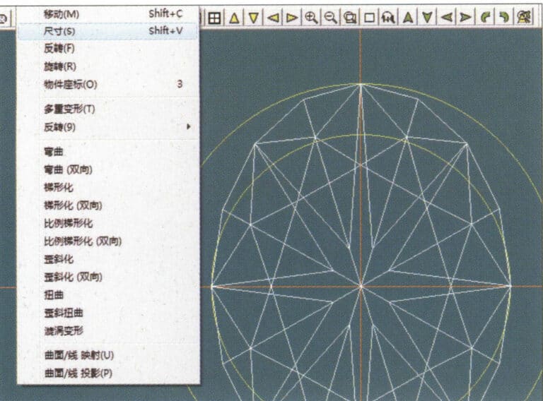
5. Select "Deformation" > "Size" from the menu bar to change the round gemstone into an oval gemstone
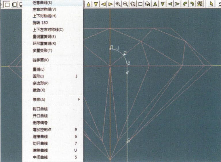
5. Select "Deformation" > "Size" from the menu bar to change the round gemstone into an oval gemstone

6. Select "Curve" > "Freeform Curve" from the menu bar to draw a claw-shaped guideline
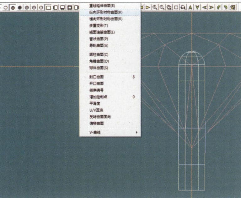
6. Select "Curve" > "Freeform Curve" from the menu bar to draw a claw-shaped guideline

7. Select "Surface" > "Longitudinal Circular Symmetrical Surface" from the menu bar, and draw a claw shape
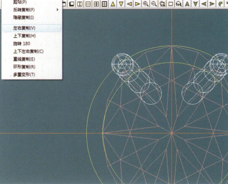
7. Select "Surface" > "Longitudinal Circular Symmetrical Surface" from the menu bar, and draw a claw shape

8. Select "Copy" > "Copy Left and Right" from the menu bar to copy the claw shape
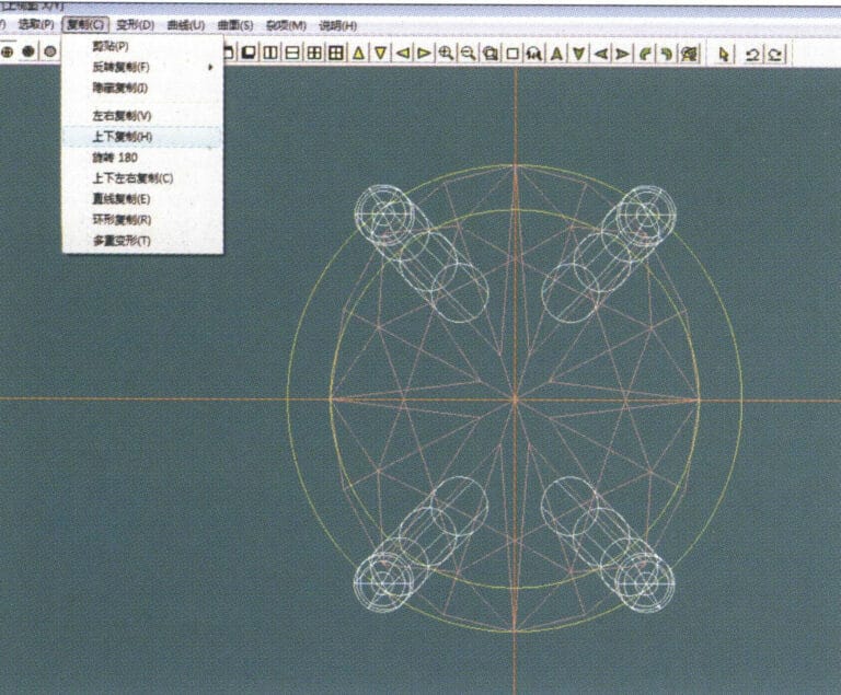
8. Select "Copy" > "Copy Left and Right" from the menu bar to copy the claw shape

9. Select "Copy" > "Copy Up and Down" from the menu bar to copy the claw shape again
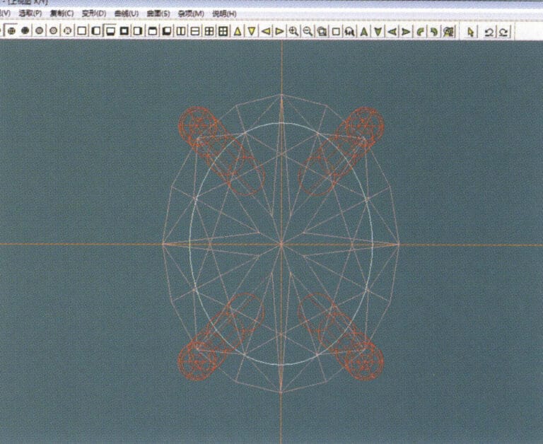
9. Select "Copy" > "Copy Up and Down" from the menu bar to copy the claw shape again

10. Select "Deformation" > "Size" from the menu bar to change the circular guideline to an elliptical guideline
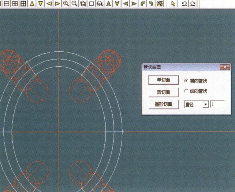
10. Select "Deformation" > "Size" from the menu bar to change the circular guideline to an elliptical guideline

11. Select "Curved Surface" > "Tubular Surface" from the menu bar, enter the relevant values in the "Tubular Surface" dialog box and confirm
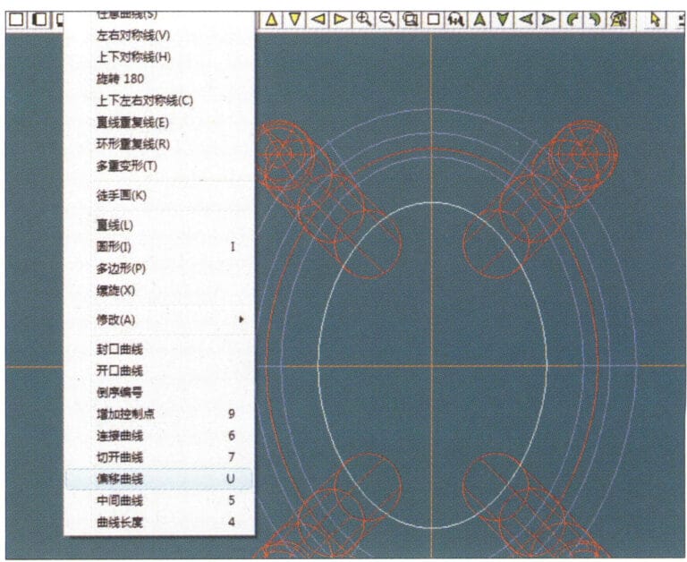
11. Select "Curved Surface" > "Tubular Surface" from the menu bar, enter the relevant values in the "Tubular Surface" dialog box and confirm

12. Select "Curve" > "Offset Curve" from the menu bar
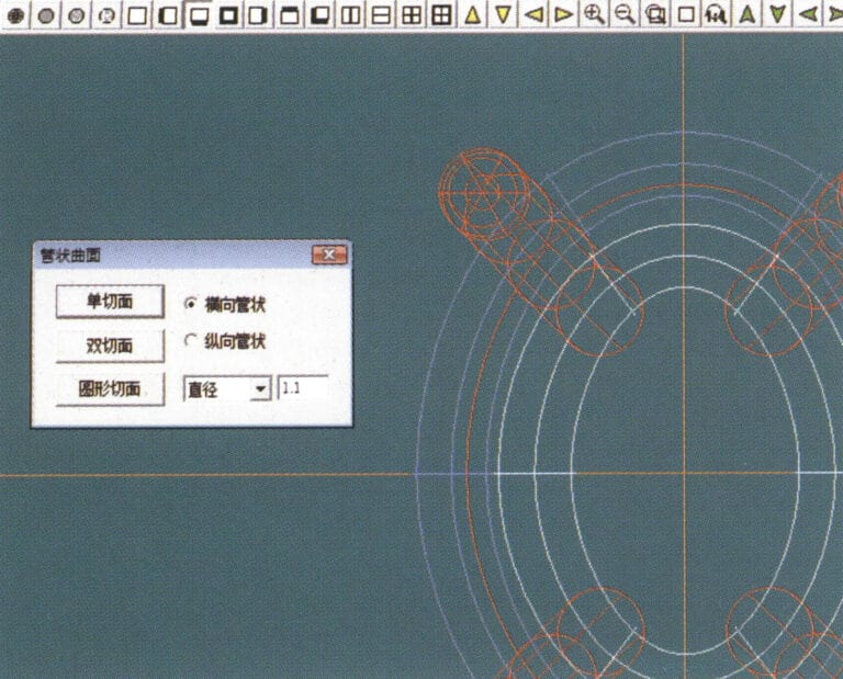
12. Select "Curve" > "Offset Curve" from the menu bar

13. Select "Surface" > "Tubular Surface" from the menu bar, enter the relevant values and confirm
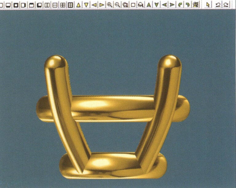
13. Select "Surface" > "Tubular Surface" from the menu bar, enter the relevant values and confirm

14. Select "View" > "Shadow Map" from the menu bar to examine the shadow effects and inspect the setting
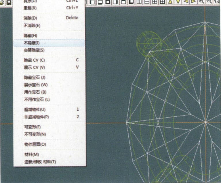
14. Select "View" > "Shadow Map" from the menu bar to examine the shadow effects and inspect the setting

15. Select "Edit" > "Unhide" from the menu bar to display the hidden gems
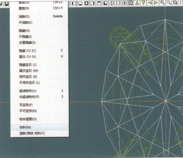
15. Select "Edit" > "Unhide" from the menu bar to display the hidden gems

16. Select "Edit" > "Materials" from the menu bar
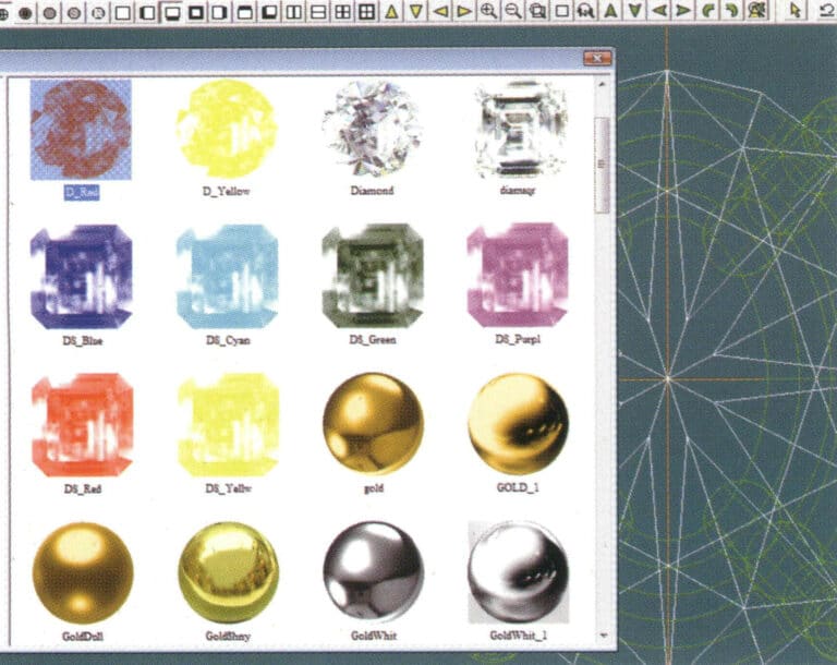
16. Select "Edit" > "Materials" from the menu bar

17. Enter the "Materials" dialog box, select ruby, and confirm
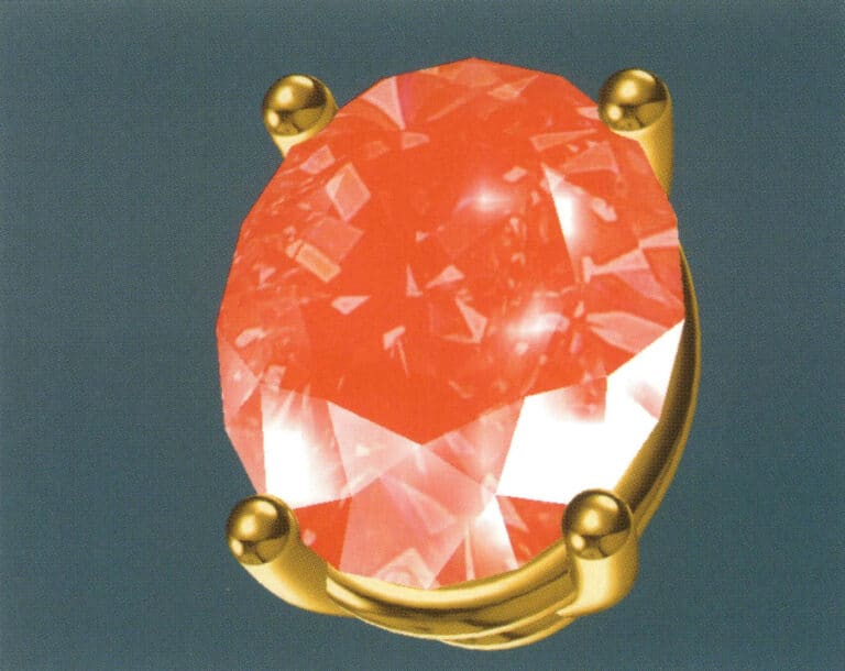
17. Enter the "Materials" dialog box, select ruby, and confirm

18. Select "View" > "Shadow Map" from the menu bar to examine the shadow effects
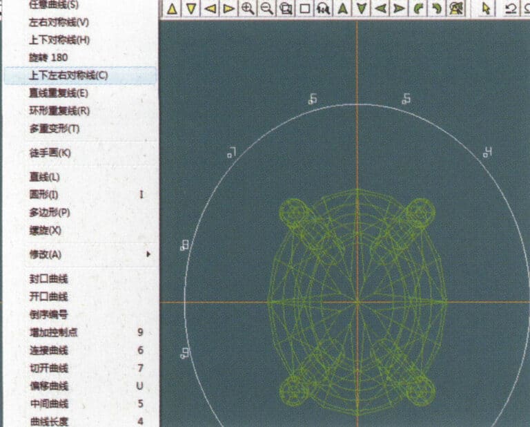
18. Select "View" > "Shadow Map" from the menu bar to examine the shadow effects

19. Select "Curve" > "Vertical and Horizontal Symmetry Line" from the menu bar as the auxiliary line for the outer circle
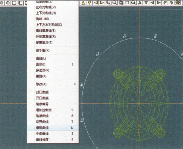
19. Select "Curve" > "Vertical and Horizontal Symmetry Line" from the menu bar as the auxiliary line for the outer circle

20. Select "Curve" > "Offset Curve" from the menu bar

20. Select "Curve" > "Offset Curve" from the menu bar

21. Войдите в диалоговое окно "Кривая смещения", введите соответствующие значения в качестве вспомогательных линий для внутренней окружности и подтвердите
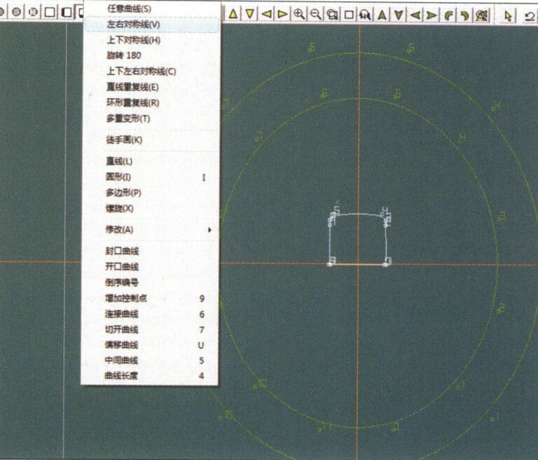
21. Войдите в диалоговое окно "Кривая смещения", введите соответствующие значения в качестве вспомогательных линий для внутренней окружности и подтвердите

22. Select "Curve" > "Left-Right Symmetrical Line" from the menu bar as the cross-section of the coil
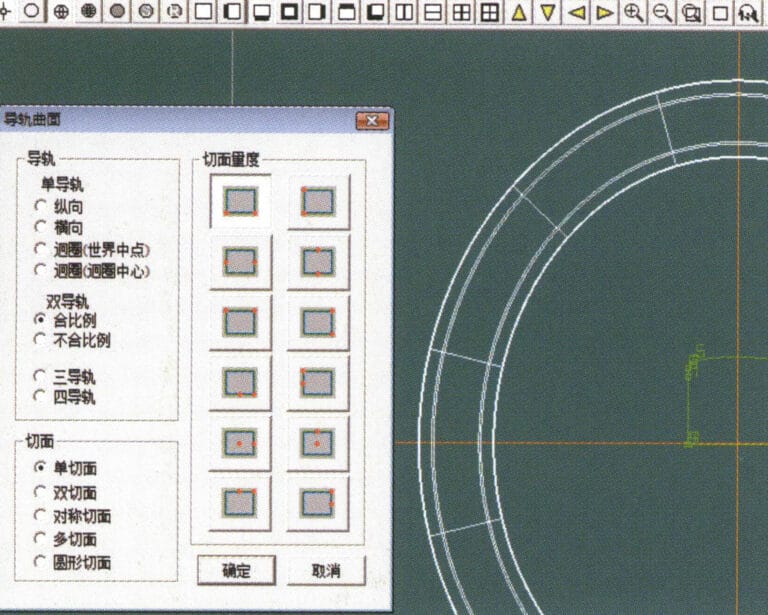
22. Select "Curve" > "Left-Right Symmetrical Line" from the menu bar as the cross-section of the coil

23. Select "Curved Surface" > "Rail Surface" from the menu bar to enter the "Rail Surface" dialog box, select the relevant options and confirm
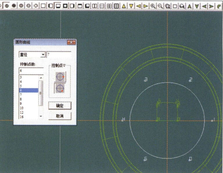
23. Select "Curved Surface" > "Rail Surface" from the menu bar to enter the "Rail Surface" dialog box, select the relevant options and confirm

24. Select "Curve" > "Circular Curve" from the menu bar, enter the relevant values in the "Circular Curve" dialog box, and confirm; left-click on one curve as the left guide curve, click on another curve as the right guide rail, and then select the coil cross-section as the cross-section of the guide rail surface; once completed, it serves as the auxiliary line for the outer circle of the chain threading position
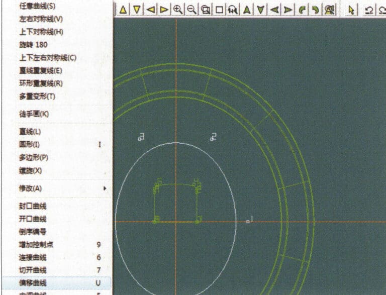
24. Select "Curve" > "Circular Curve" from the menu bar, enter the relevant values in the "Circular Curve" dialog box, and confirm; left-click on one curve as the left guide curve, click on another curve as the right guide rail, and then select the coil cross-section as the cross-section of the guide rail surface; once completed, it serves as the auxiliary line for the outer circle of the chain threading position

25. After completing the outer auxiliary lines for the chain position, select "Curve" > "Offset Curve" from the menu bar
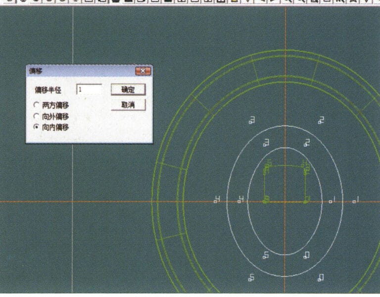
25. After completing the outer auxiliary lines for the chain position, select "Curve" > "Offset Curve" from the menu bar

26. Enter the "Offset Curve" dialog box, input the relevant values, and confirm
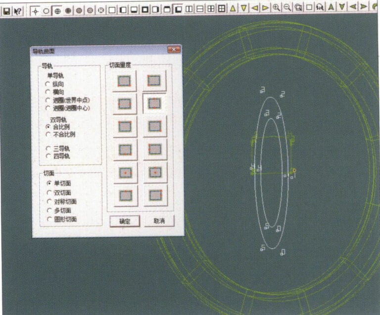
26. Enter the "Offset Curve" dialog box, input the relevant values, and confirm

27. Select "Surface" > "Rail Surface" from the menu bar to enter the "Rail Surface" dialog box, select the relevant options and confirm, left-click on a curve to set it as the left rail curve, click on another curve to set it as the right rail, and then select the coil cross-section as the cross-section of the rail surface
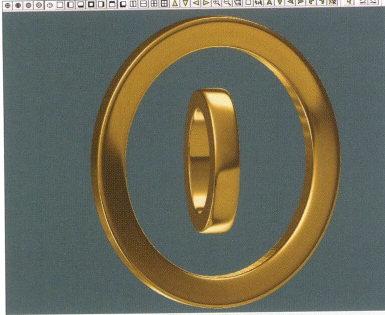
27. Select "Surface" > "Rail Surface" from the menu bar to enter the "Rail Surface" dialog box, select the relevant options and confirm, left-click on a curve to set it as the left rail curve, click on another curve to set it as the right rail, and then select the coil cross-section as the cross-section of the rail surface

28. Select "View" > "Shadow Map" from the menu bar to inspect the shadow effects
28. Select "View" > "Shadow Map" from the menu bar to inspect the shadow effects

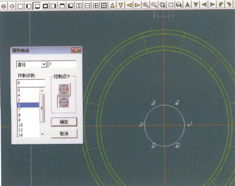
29. Select "Curve" > "Circular Curve" from the menu bar, enter the relevant values and confirm
29. Select "Curve" > "Circular Curve" from the menu bar, enter the relevant values and confirm

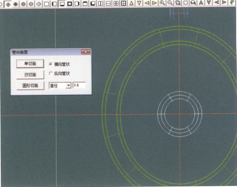
30. Select "Curved Surface" > "Tubular Surface" from the menu bar, enter the relevant values and confirm
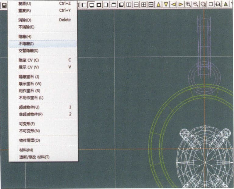
30. Select "Curved Surface" > "Tubular Surface" from the menu bar, enter the relevant values and confirm

31. Select "Edit" > "Unhide" from the menu bar to display the hidden objects
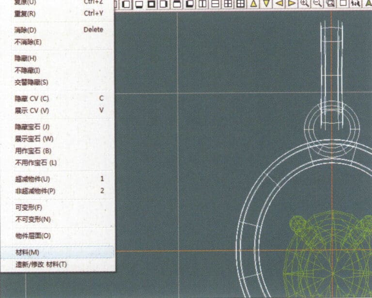
31. Select "Edit" > "Unhide" from the menu bar to display the hidden objects

32. Select "Edit" > "Materials" from the menu bar
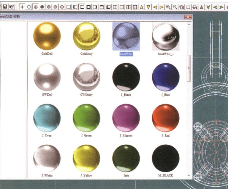
32. Select "Edit" > "Materials" from the menu bar

33. Enter the "Materials" dialog box, select the relevant materials and confirm
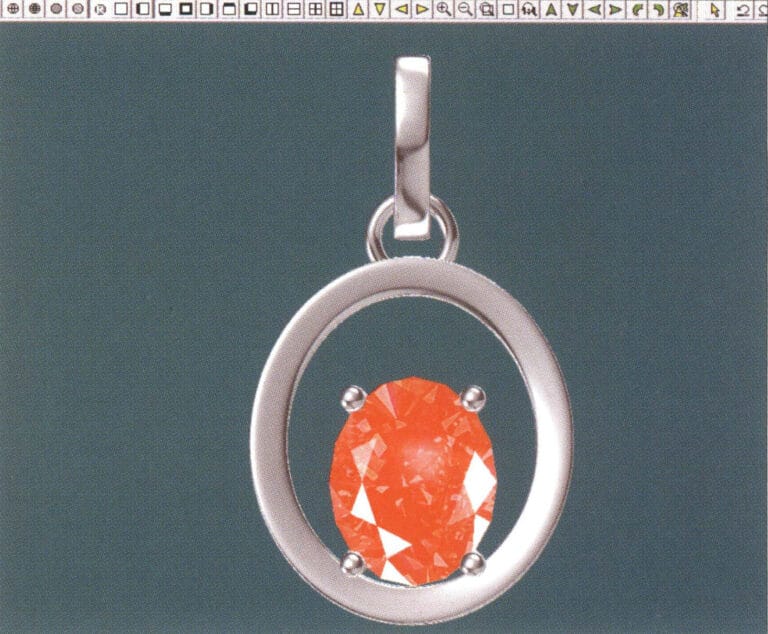
33. Enter the "Materials" dialog box, select the relevant materials and confirm

34. Select "View" > "Shadow Map" from the menu bar to inspect the shadow effects
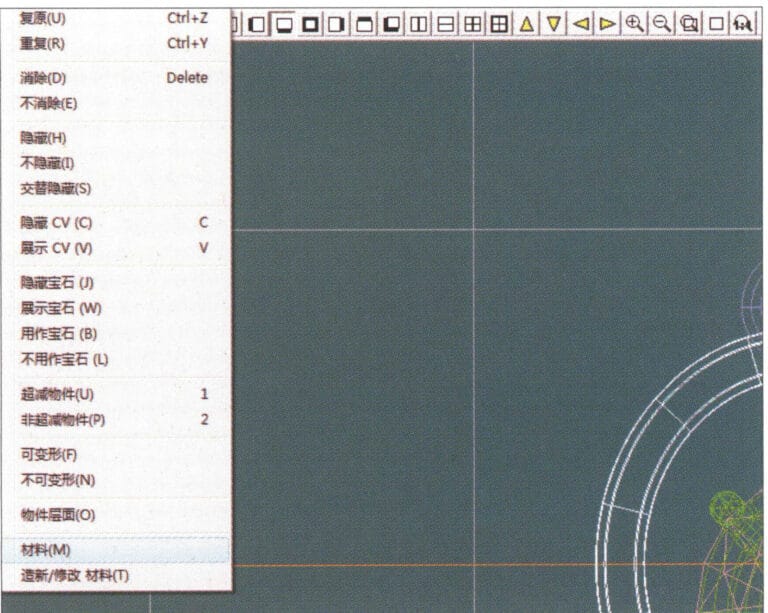
34. Select "View" > "Shadow Map" from the menu bar to inspect the shadow effects

35. Select "Edit" > "Materials" from the menu bar
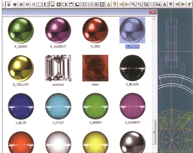
35. Select "Edit" > "Materials" from the menu bar

36. Enter the "Materials" dialog box, select the relevant texture materials and confirm
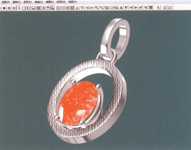
36. Enter the "Materials" dialog box, select the relevant texture materials and confirm

37. Select "View" > "Shadow Map" from the menu bar to inspect the shadow effects 38. Select "File" > "Save As" from the menu bar to save the file

37. Select "View" > "Shadow Map" from the menu bar to inspect the shadow effects

38. Select "File" > "Save As" from the menu bar to save the file

Изображение Хемана
Хеман

Эксперт по ювелирным изделиям --- 12 лет богатого опыта

Привет, дорогая,

Я - Хеман, папа и герой двух замечательных детей. Я рад поделиться своим ювелирным опытом в качестве эксперта по ювелирным изделиям. С 2010 года я обслуживаю 29 клиентов со всего мира, таких как Hiphopbling и Silverplanet, помогая и поддерживая их в творческом ювелирном дизайне, разработке и производстве ювелирных изделий.

Если у вас есть какие-либо вопросы о ювелирной продукции, не стесняйтесь звонить или писать мне, и давайте обсудим подходящее решение для вас, и вы получите бесплатные образцы ювелирных изделий, чтобы проверить мастерство и качество ювелирных деталей.

Давайте расти вместе!

Добавить комментарий

Ваш адрес электронной почты не будет опубликован. Обязательные поля помечены *

Категории ПОСТОВ

Нужна поддержка ювелирного производства?

Отправьте запрос в Sobling
202407 heman - эксперт по ювелирным изделиям
Хеман

Эксперт по ювелирным изделиям

Привет, дорогая,

Я - Хеман, папа и герой двух замечательных детей. Я рад поделиться своим ювелирным опытом в качестве эксперта по ювелирным изделиям. С 2010 года я обслуживаю 29 клиентов со всего мира, таких как Hiphopbling и Silverplanet, помогая и поддерживая их в творческом ювелирном дизайне, разработке и производстве ювелирных изделий.

Если у вас есть какие-либо вопросы о ювелирной продукции, не стесняйтесь звонить или писать мне, и давайте обсудим подходящее решение для вас, и вы получите бесплатные образцы ювелирных изделий, чтобы проверить мастерство и качество ювелирных деталей.

Давайте расти вместе!

Следуй за мной

Почему стоит выбрать Sobling?

Члены команды Sobling серебряные украшения производитель и завод
СЕРТИФИКАТЫ

Sobling соблюдает стандарты качества

Sobling соответствует сертификатам качества TUV CNAS CTC

Самые новые посты

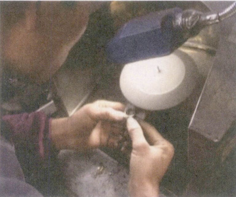
Рисунок 4-37 Шлифование с помощью летающего диска

Как выполнить финишную обработку ювелирных изделий?

Преобразите свое ювелирное дело с помощью советов экспертов по технике отделки. Научитесь собирать, сваривать и полировать изделия, добиваясь безупречных результатов. Незаменим для ювелиров, студий и дизайнеров, создающих элитные изделия на заказ.

Читать далее "
Рисунок 2-11 Использование яркого красного цвета для выделения бренда

Как создать идеальную витрину и пространство для ювелирного магазина?

В этом руководстве рассматриваются ключевые аспекты оформления и демонстрации ювелирных магазинов. В него включены советы по внешнему виду, входу, освещению и оформлению витрин. Узнайте, как организовать планировку магазина, выбрать материалы и создать безопасные витрины. Идеально подходит для ювелирных магазинов, брендов, дизайнеров и онлайн-продавцов.

Читать далее "
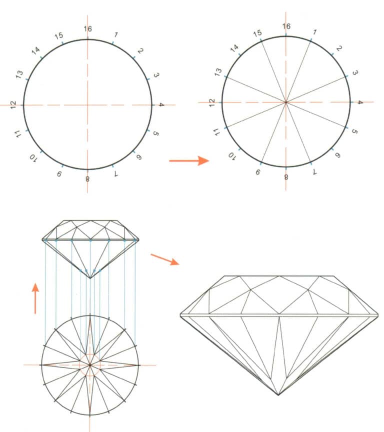
Рисунок 2-32 Стандартный круглый павильон типа Brilliant - метод ручного рисования

Как сделать дизайн огранки драгоценных камней? Формирование, техника рисования и пропорции для ювелиров

Это руководство научит ювелиров разрабатывать дизайн и огранять драгоценные камни для максимального блеска. В нем рассматриваются основы огранки драгоценных камней, углы для придания яркости, а также различные формы - круглая, овальная и грушевидная. Это обязательное чтение для всех, кто делает украшения на заказ.

Читать далее "
Кольцо из нержавеющей стали

Что делает нержавеющую сталь и титановый сплав идеальным материалом для ювелирных изделий? Производственная информация и тенденции рынка

В этой статье описывается процесс производства ювелирных изделий из нержавеющей стали и титана, включая механическую формовку и литье по выплавляемым моделям. В ней рассматриваются особенности, тенденции рынка и распространенные типы этих материалов, что дает практическую информацию для ювелирных магазинов, студий, брендов, розничных продавцов, дизайнеров и онлайн-продавцов.

Читать далее "
Материал серебро 999 пробы 2

Изучите материалы из чистого серебра и серебряных сплавов, используемые для изготовления ювелирных изделий

Серебряные украшения сияют красотой и стабильностью, но потускнение - это угроза. В нашем руководстве мы расскажем, как повысить устойчивость серебра к потускнению и обесцвечиванию с помощью контроля чистоты и грамотного легирования. Это обязательное чтение для профессионалов ювелирного дела, желающих создавать долговечные серебряные изделия.

Читать далее "
Выразите свои ювелирные идеи с помощью ручной росписи

Как выразить свои ювелирные идеи с помощью ручной росписи? Техника, советы и примеры.

Научитесь рисовать украшения как профессионал! Это руководство научит вас шаг за шагом рисовать кольца, серьги, броши и кулоны. В нем вы найдете советы по работе с драгоценными камнями, металлами и деталями. Идеально подходит для ювелирных дизайнеров, магазинов и всех, кто хочет создавать удивительное ювелирное искусство!

Читать далее "
Ювелирные изделия с муассанитом, выращенным в лаборатории

Что такое муассанит? Полное руководство по использованию муассанита в ювелирных изделиях

Муассанит - это сверкающий драгоценный камень, который похож на бриллианты, но стоит гораздо дешевле. Он производится в лабораториях, поэтому является экологически чистым и этичным. Отлично подходит для колец, браслетов и многого другого. Поставляется в различных цветах и огранках. Идеально подходит для ювелирных магазинов, дизайнеров и онлайн-продавцов.

Читать далее "

10% Off !!!

При каждом первом заказе

Присоединяйтесь к нашей рассылке

Подпишитесь, чтобы получать последние обновления и предложения!

Производитель ювелирных изделий Sobling Получить цену для вашего украшения
Ultimate guide sourcing - 10 советов, которые помогут вам сэкономить миллионы на поиске новых поставщиков
Скачать бесплатно

Полное руководство по поиску поставщиков для бизнеса

10 ценных советов помогут вам сэкономить миллионы на поиске новых поставщиков ювелирных изделий
Производитель ювелирных изделий Sobling бесплатная настройка для ваших ювелирных изделий

Ювелирный завод, изготовление ювелирных изделий на заказ,Ювелирный завод Moissanite,Ювелирные изделия из меди,Полудрагоценные ювелирные изделия,Синтетические драгоценные камни,Пресноводный жемчуг,Стерлинговое серебро CZ ювелирные изделия,Полудрагоценные камни на заказ,Синтетические драгоценные камни ювелирные изделия