Comment créer des modèles de bijoux en 3D avec JewelCAD ?
Comprendre JewelCAD, représenter les effets de matière de base et les effets de bijouterie
Introduction :
Que faut-il pour créer de superbes modèles de bijoux avec JewelCAD ? Ce guide couvre tous les aspects, de la compréhension du logiciel à la maîtrise des effets de matière, en passant par la création de modèles de bijoux détaillés. Apprenez à donner vie à vos idées grâce à des instructions pas à pas pour concevoir des bagues, des pendentifs et bien plus encore. Découvrez pourquoi JewelCAD est un outil indispensable pour les créateurs de bijoux, les studios et les marques qui cherchent à améliorer leur travail.
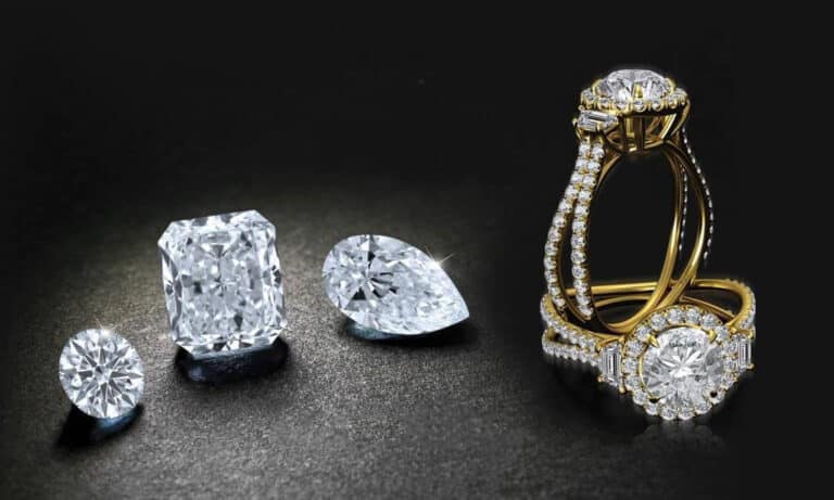
Bague à sertissage de diamants tournés
Table des matières
Section I Comprendre JewelCAD
JewelCAD est un logiciel de conception assistée par ordinateur spécialement conçu pour la bijouterie, qui a été développé avec succès par une entreprise de CAO/FAO de Hong Kong en 1990. Après plus d'une décennie de développement et d'amélioration, JewelCAD est passé d'un logiciel de dessin aux fonctions limitées à un logiciel professionnel de conception/fabrication de bijoux puissant, stable, hautement spécialisé et efficace, largement adopté dans les principales zones de production de bijoux en Europe, en Amérique et en Asie.
Alors que l'automatisation de la production et du traitement dans l'industrie de la bijouterie a considérablement amélioré l'efficacité, JewelCAD correspond à la conception moderne des bijoux et a été largement diffusé dans les applications commerciales actuelles. Ses concepts et outils de modélisation uniques permettent aux concepteurs de bijoux de créer facilement des objets tridimensionnels, et ils s'intègrent parfaitement au prototypage rapide CNC et RP, ce qui en fait un logiciel de conception de bijoux moderne avec de vastes perspectives de développement. En tant que logiciel professionnel de conception de bijoux, JewelCAD présente des avantages indéniables par rapport aux autres logiciels 3D pour la création de modèles tridimensionnels de bijoux, comme en témoignent les avantages suivants.
(1) Facile à utiliser, simple et facile à apprendre.
(2) Il dispose d'outils de dessin flexibles, très pratiques pour dessiner des courbes et des formes complexes.
(3) Il dispose de puissants outils de modélisation des surfaces qui permettent de créer ou de modifier des conceptions complexes en toute souplesse.
(4) La vitesse de rendu est rapide ; vous pouvez également comparer plusieurs images d'effets de conception. La qualité des images d'effet est élevée et la simulation est puissante. Il apermet d'observer l'effet tridimensionnel, reflétant intuitivement l'effet du produit final.
(5) Son fonctionnement est très efficace et convient aux styles de bijoux changeants.
(6) Une riche base de données professionnelle et divers outils d'édition facilitent la combinaison et la refonte des bijoux, ce qui rend les opérations plus pratiques et plus efficaces.
(7) L'application des principes des opérations booléennes dans les logiciels permet d'unir facilement des surfaces à l'état libre.
(8) Dans le modèle, le poids de l'or, la quantité et la taille peuvent être calculés directement.
(9) Peut créer une base de données pour visualiser les idées de conception et améliorer l'efficacité.
(10) Les graphiques dessinés avec JewelCAD sont plus clairs et plus cohérents, ce qui réduit la probabilité d'erreurs dues à une écriture peu claire ou à une mauvaise qualité de dessin. JewelCAD peut produire directement des images sans papier, ce qui permet d'économiser du temps, des efforts et de l'argent.
Section II Utilisation de JewelCAD pour représenter les effets de base des matériaux
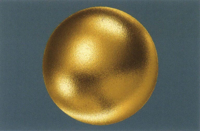
1. Effet de finition par sablage
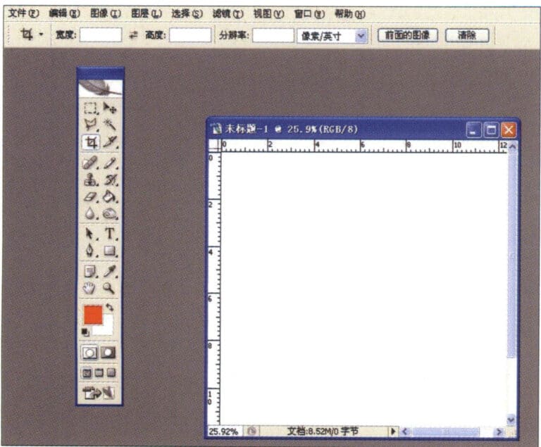
1. Créez un nouveau fichier dans Photoshop avec une résolution de 300 pixels/pouce.
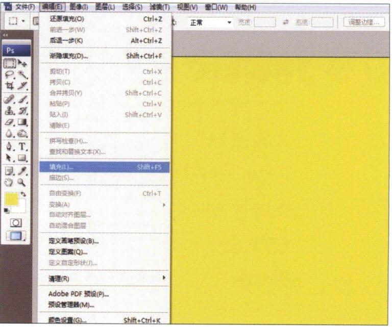
2. Select "Edit" > "Fill" from the menu bar, and set the foreground color to yellow

3. Select "Filter" from the menu bar > "Mottled" > "Add Mottled"
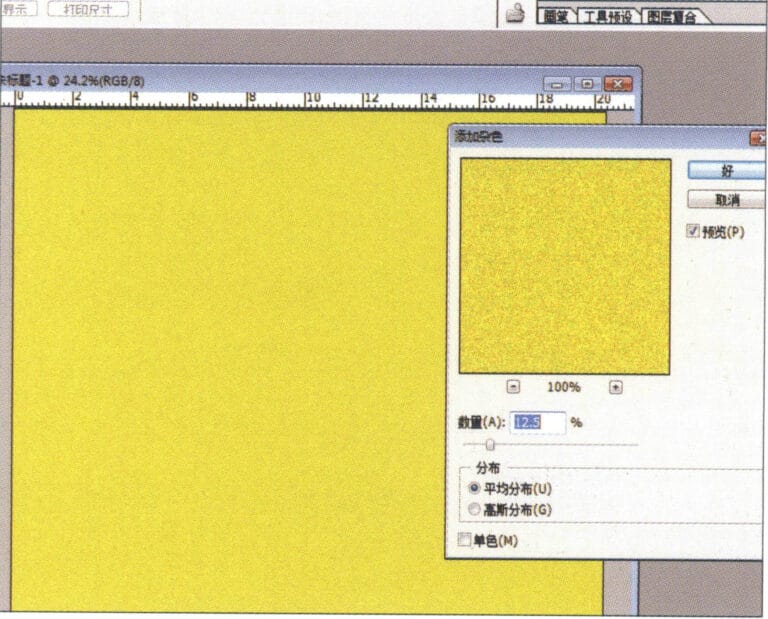
4. Entrez dans la boîte de dialogue "Add Mottled", saisissez les valeurs appropriées et confirmez.
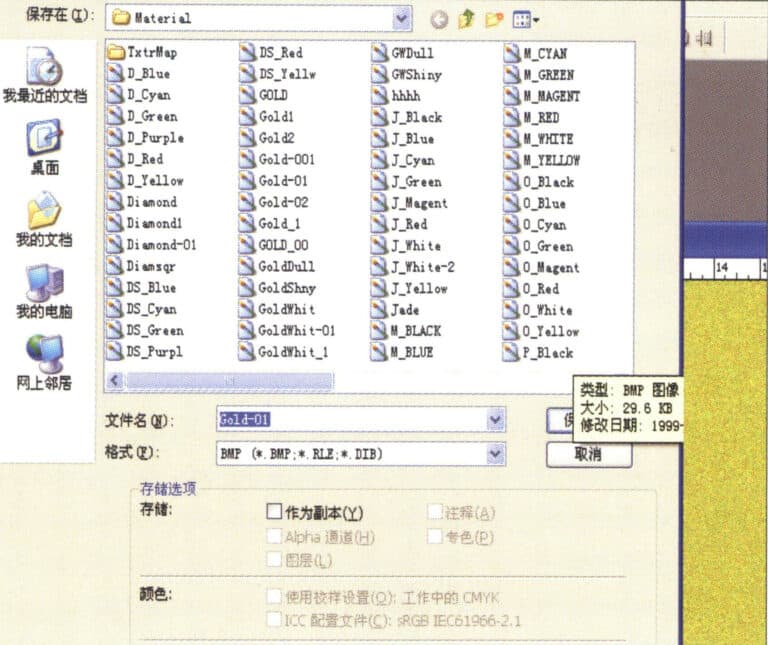
5. Store the document in the "JewelCAD" > "Material" folder, saved in "BMP" format

6. Create a new file in JewelCAD, select "Surface" > "Spherical Surface" from the menu bar
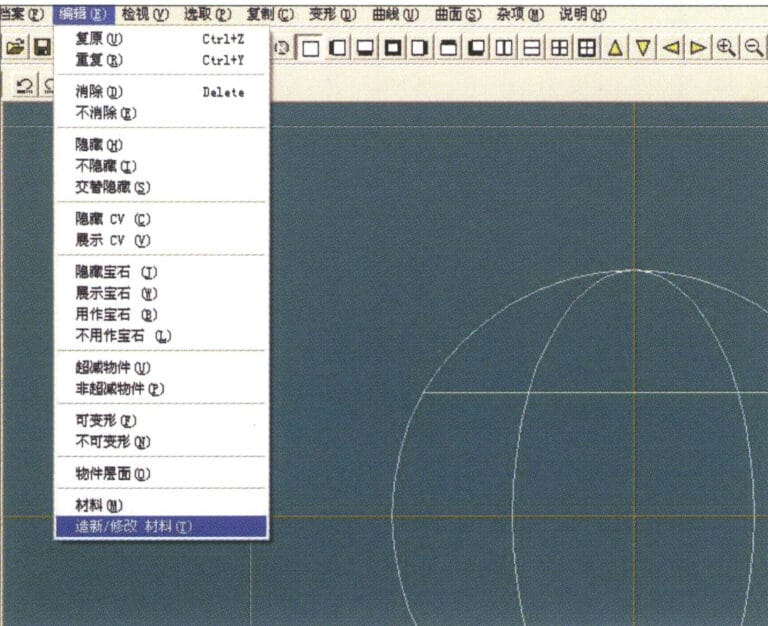
7. Select "Edit" > "Create/Modify Material" from the menu bar
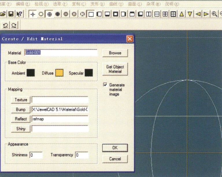
8. Entrez dans la boîte de dialogue "Créer/Modifier un matériau", saisissez les valeurs appropriées et confirmez.
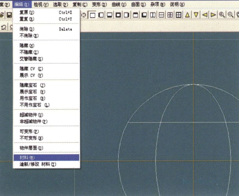
9. Select "Edit" > "Materials" from the menu bar
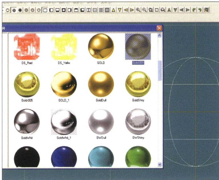
10. Entrez dans la boîte de dialogue "Matériaux", sélectionnez le matériau et confirmez.
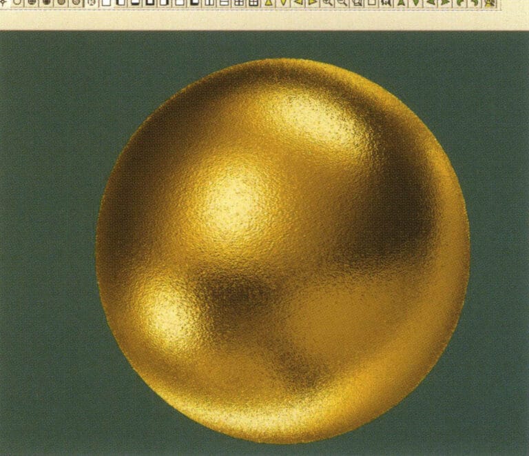
11. Select "View" > "Shadow Map" from the menu bar to inspect the shadow effects.
12. Select "File" > "Save File" from the menu bar to save the document
2. Effet de brossage
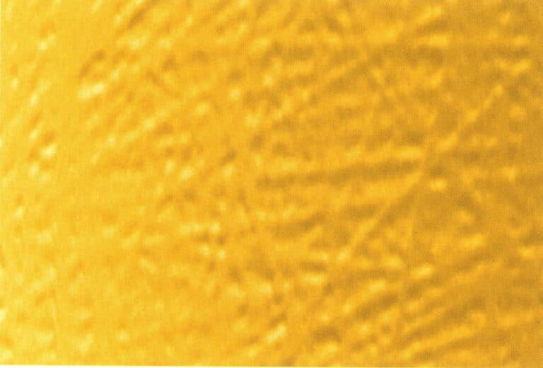

1. Scan a texture file in Photoshop with a resolution of 300 pixels/inch, and select "Filter" > "Blur" > "Motion Blur" from the menu bar to apply the blur effect
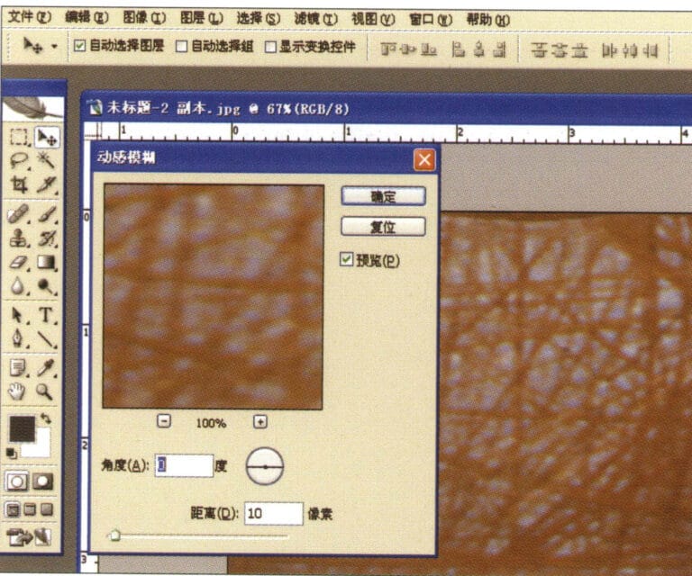
2. Entrez dans la boîte de dialogue "Flou de mouvement", saisissez les valeurs appropriées et confirmez.
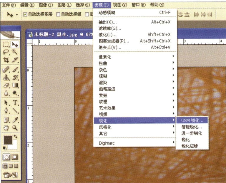
3. Select "Filter" > "Sharpen" > "USM Sharpening" from the menu bar
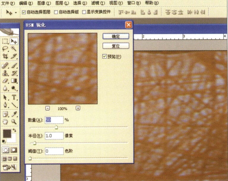
4. Entrez dans la boîte de dialogue "USM Sharpening", saisissez les valeurs appropriées et confirmez.
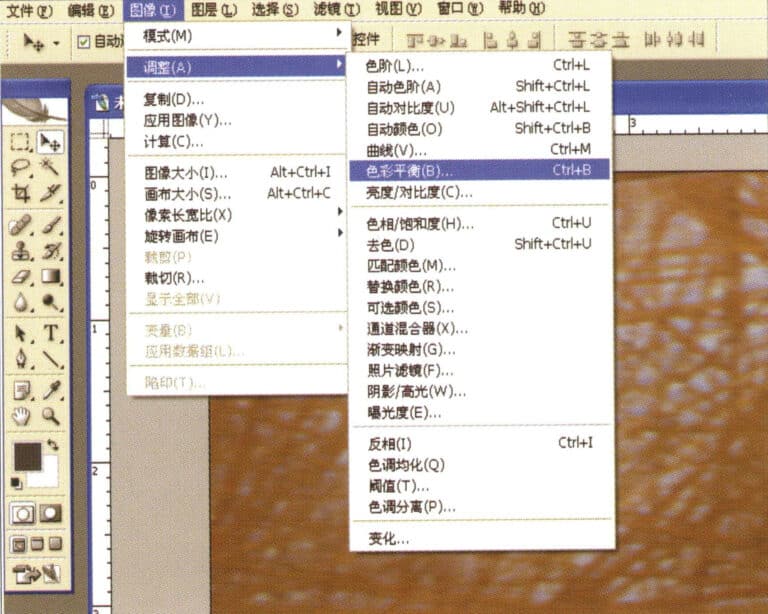
5. Select "Image" > "Adjustments" > "Color Balance" from the menu bar
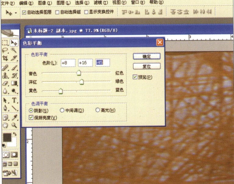
6. Entrez dans la boîte de dialogue "Balance des couleurs", saisissez les valeurs appropriées et confirmez.
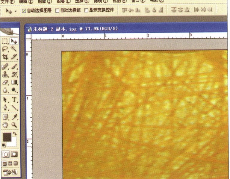
7. Diagramme d'effet après l'affichage de la balance des couleurs
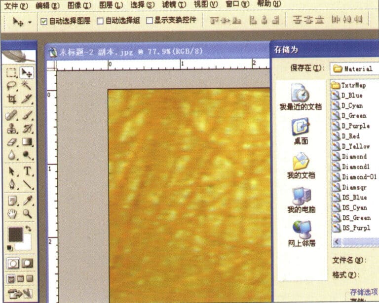
8. Store the document in the "JewelCAD" > "Material" folder, saved in "BMP" format
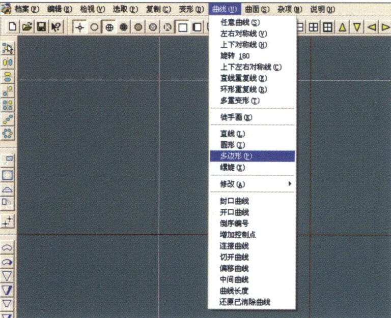
9. In JewelCAD, create a new file, select "Curve" > "Polygon" from the menu bar
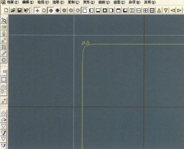
10. Utiliser "polygone" pour dessiner un carré
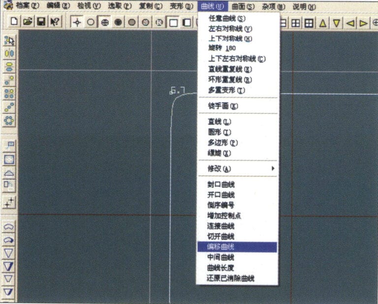
11. Select "Curve" > "Offset Curve" from the menu bar
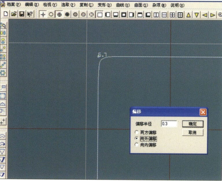
12. Entrez dans la boîte de dialogue "Courbe de décalage", saisissez les valeurs appropriées et confirmez.
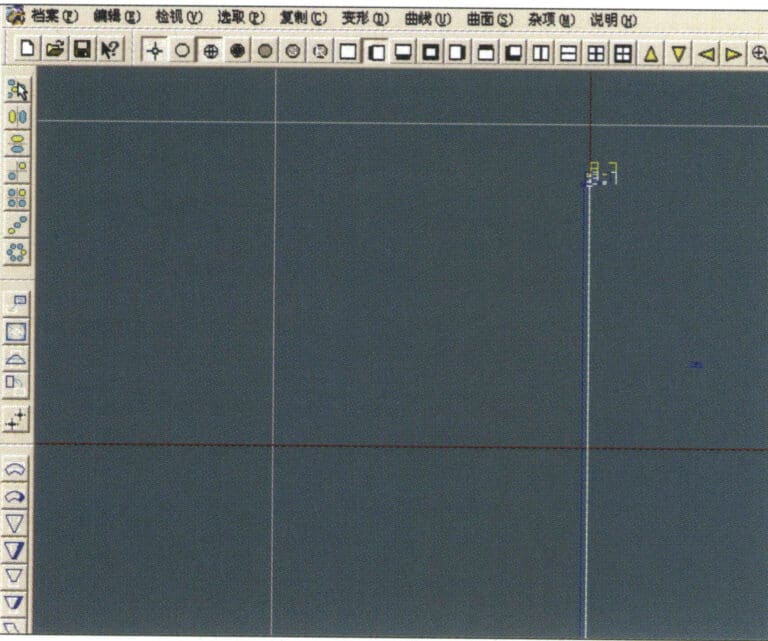
13. Diagramme d'effet après l'affichage de la courbe de décalage
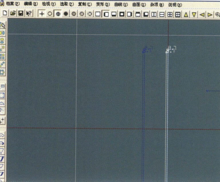
14. Select "Deformation" > "Move" from the menu bar to move the selected curve
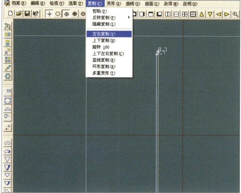
15. Select "Copy" > "Copy Left and Right" from the menu bar to copy the selected curve to the left and right
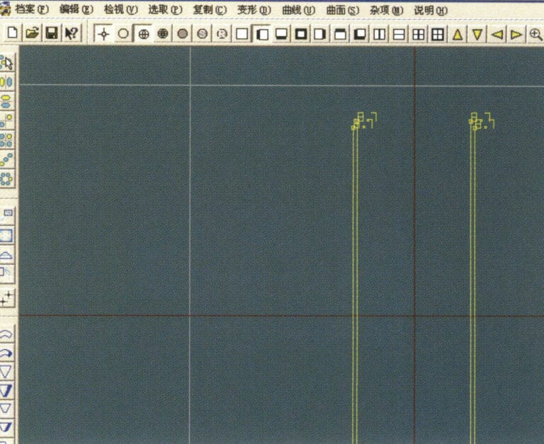
16. Afficher les images de l'effet après duplication à gauche et à droite
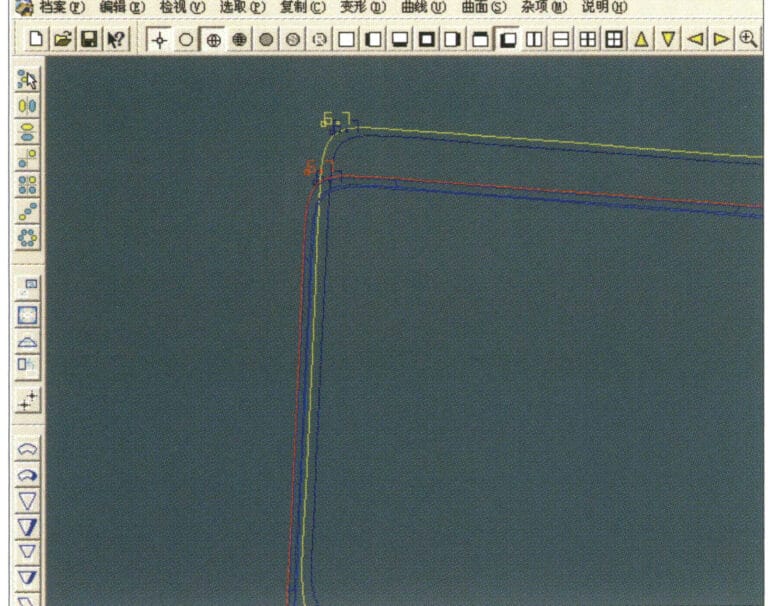
17. Select "Surface" > "Curve Surface Connection" from the menu bar, and double-click the first and second curves/surfaces in a clockwise direction with the left mouse button to create a curve surface connection
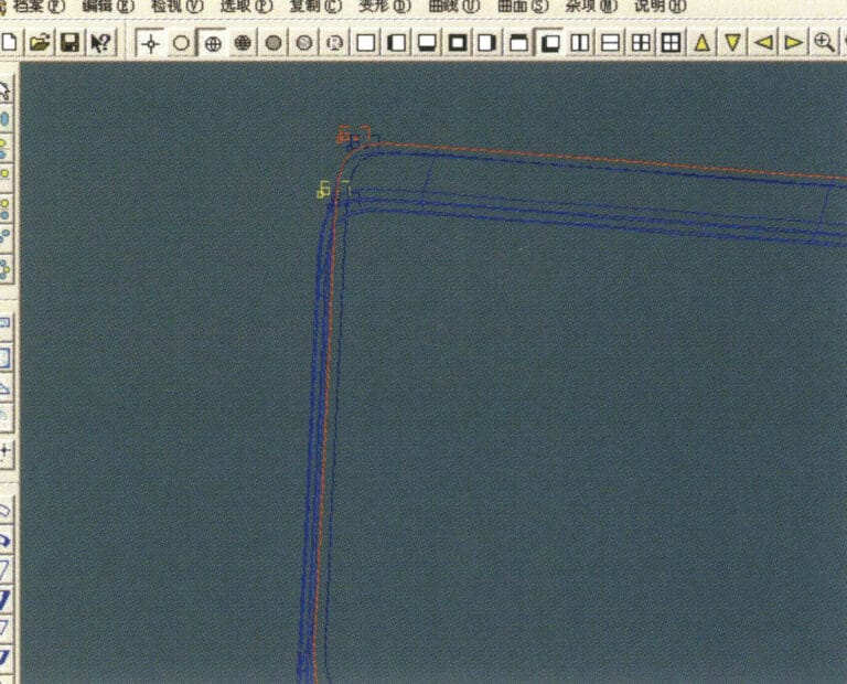
18. Dans le sens des aiguilles d'une montre, double-cliquez sur la troisième courbe/surface avec le bouton gauche de la souris pour créer une connexion ligne-surface
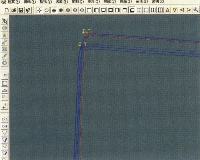
19. Continuez dans le sens des aiguilles d'une montre ; double-cliquez sur la quatrième courbe/surface avec le bouton gauche de la souris pour créer une connexion ligne-surface.

20. Select "View" > "Shadow Map" from the menu bar to inspect the shadow effects
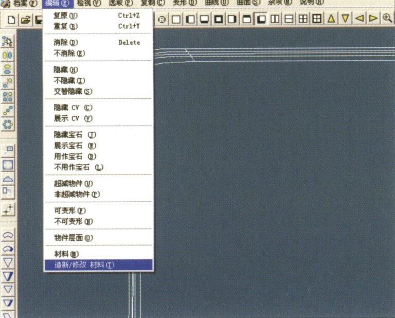
21. Select "Edit" > "Create/Modify Material" from the menu bar
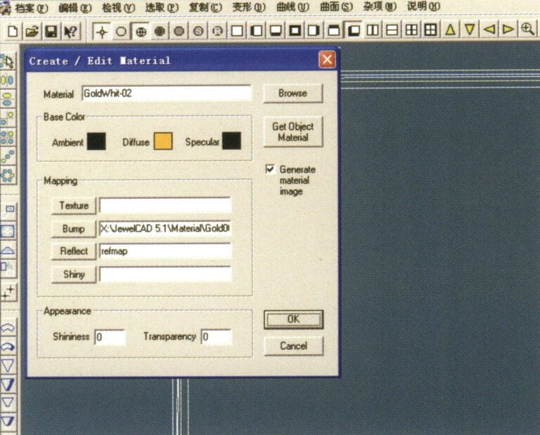
22. Entrez dans la boîte de dialogue "Créer/Modifier un matériau", saisissez les valeurs appropriées et confirmez.
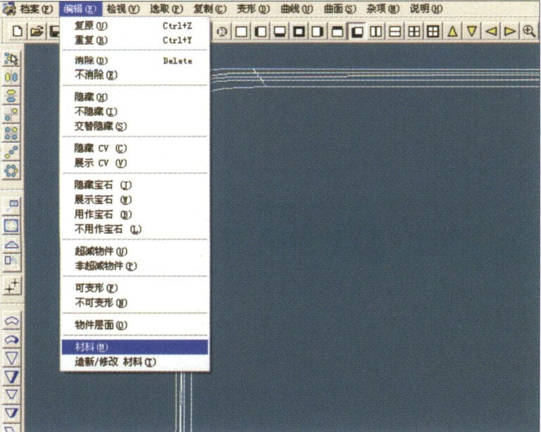
23. Select "Edit" > "Materials" from the menu bar
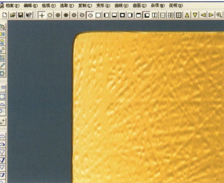
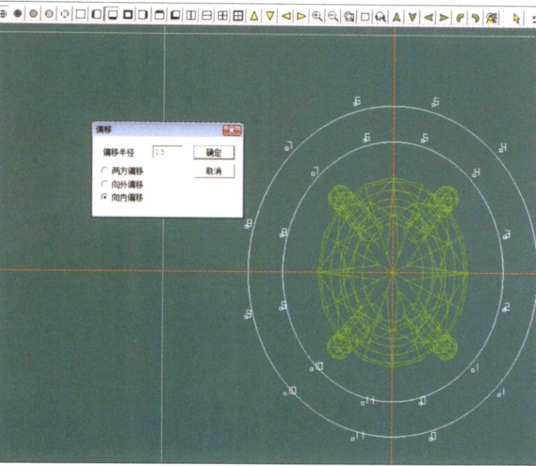
24. Select "View" > "Shadow Map" on the menu bar to view the light and shadow effects 25. Select "File" > "Save File" on the menu bar to save the file
3. Texture de l'écorce
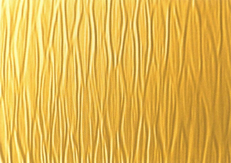

1. Numériser un fichier de texture dans Photoshop avec une résolution de 300 pixels/pouce.
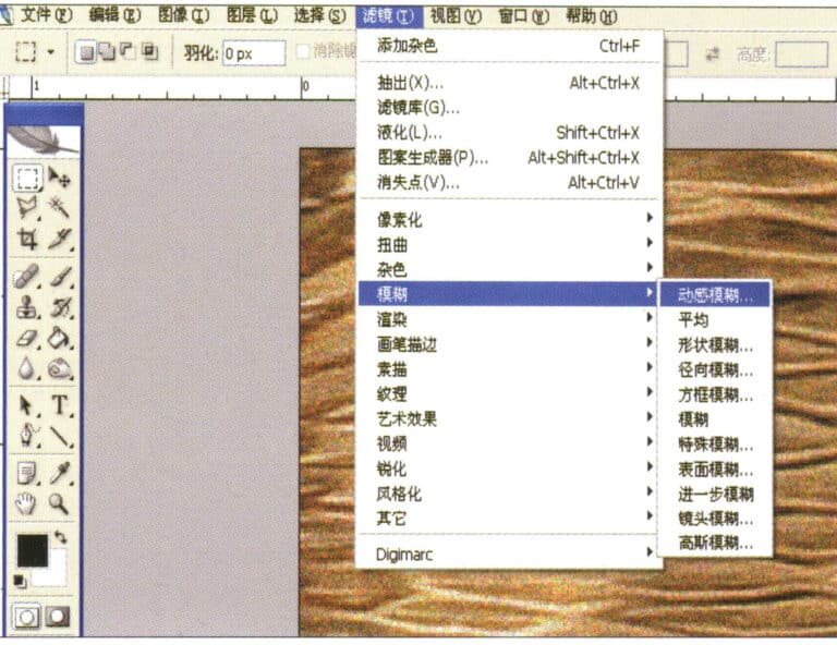
2. Select "Filter" > "Blur" > "Motion Blur" from the menu bar
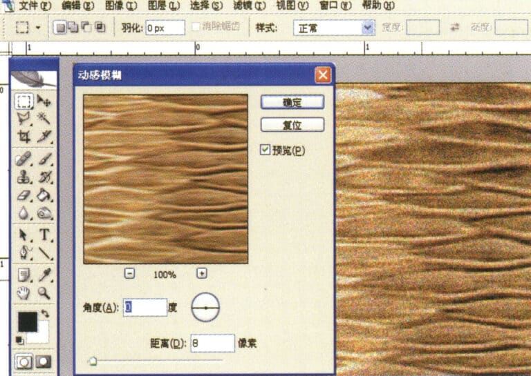
3. Entrez dans la boîte de dialogue "Flou de mouvement", saisissez les valeurs appropriées et confirmez.
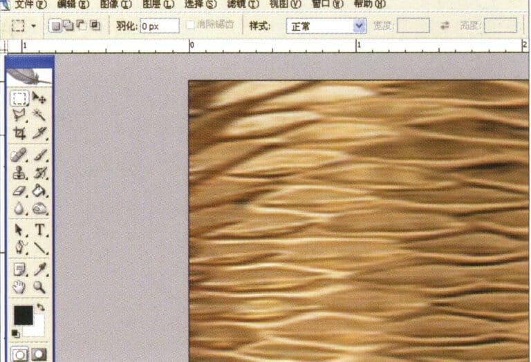
4. Afficher l'image de l'effet après le flou de mouvement
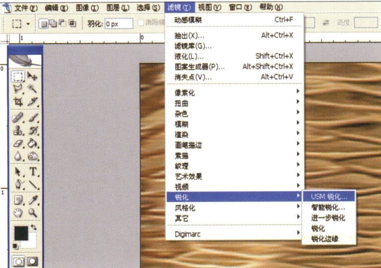
5. Select "Filter" > "Sharpen" > "USM Sharpening" from the menu bar
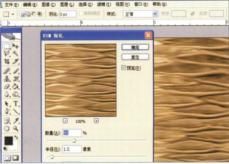
6. Entrez dans la boîte de dialogue "USM Sharpening", saisissez les valeurs appropriées et confirmez.
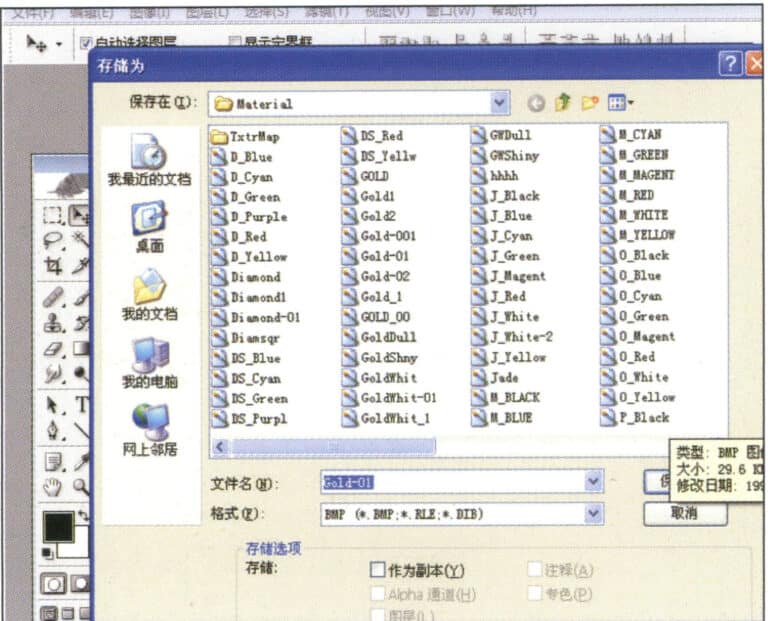
7. Store the document in the "JewelCAD" > "Material" folder and save it in "BMP" format
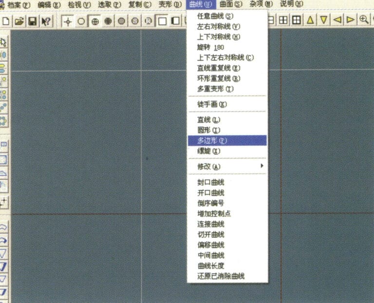
8. In JewelCAD, create a new file, select "Curve" > "Polygon" from the menu bar
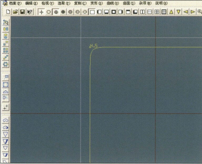
9. Utiliser "polygone" pour dessiner un carré
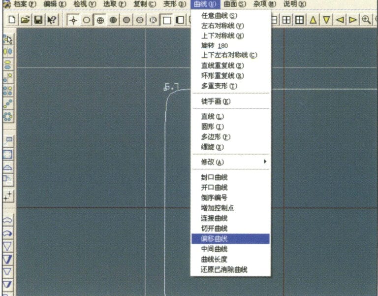
10. Select "Curve" > "Offset Curve" from the menu bar
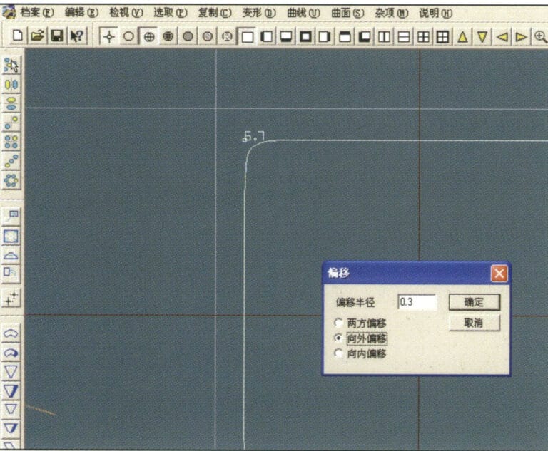
11. Entrez dans la boîte de dialogue "Courbe de décalage", saisissez les valeurs appropriées et confirmez.
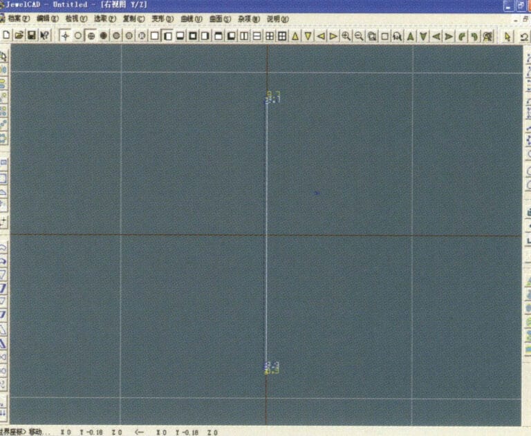
12. Diagramme d'effet après l'affichage de la courbe de décalage
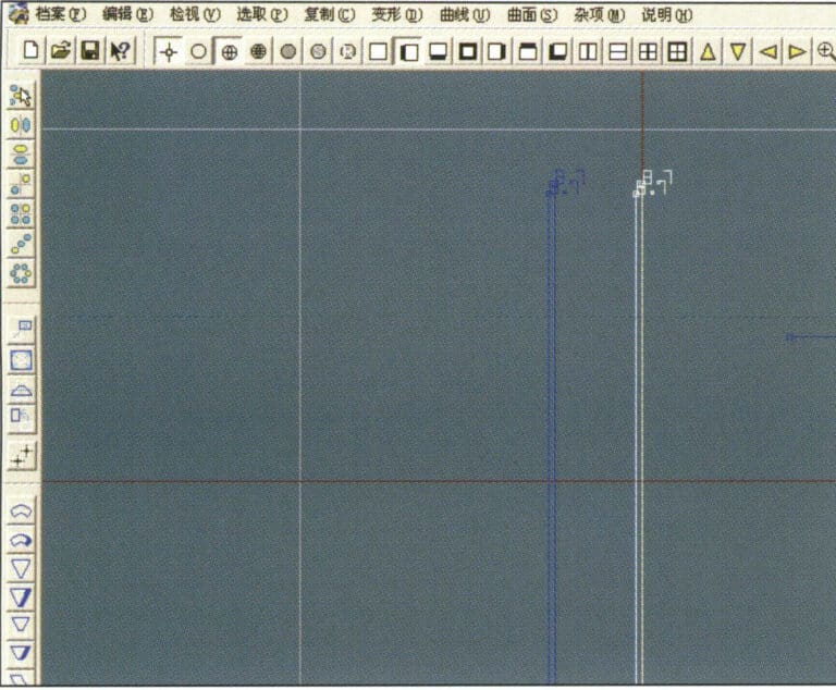
13. Select "Deformation" > "Move" from the menu bar to move the selected curve
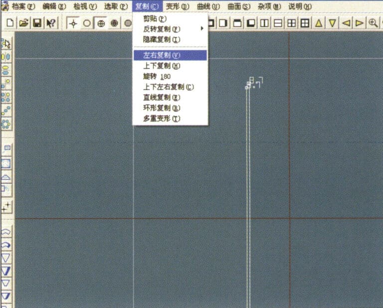
14. Select "Copy" > "Copy Left and Right" from the menu bar to copy the selected curve to the left and right
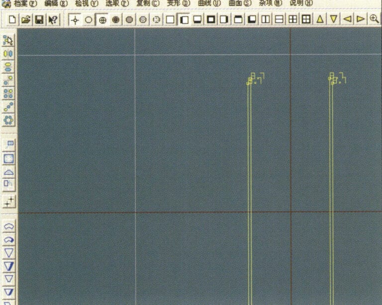
15. Afficher les images de l'effet après la copie à gauche et à droite
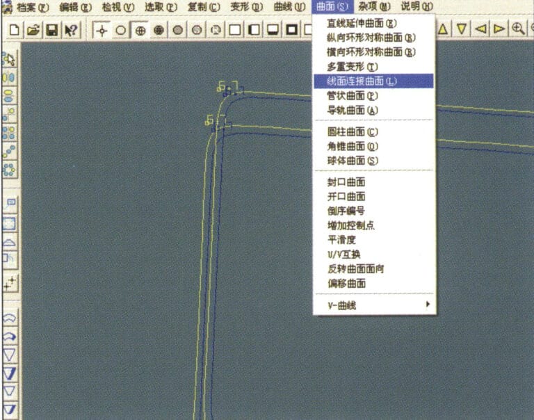
16. Select "Surface" > "Line-Surface Connection Surface" from the menu bar, and select the curve/surface to create a line-surface connection surface
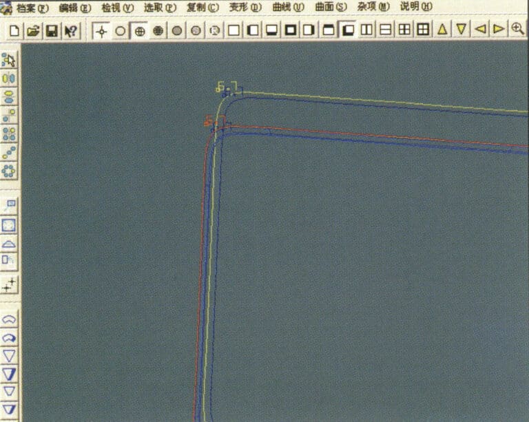
17. Select the menu bar "Surface" > "Curve Surface Connection," and double-click the first and second curves/surfaces with the left mouse button in a clockwise direction to create a curve surface connection
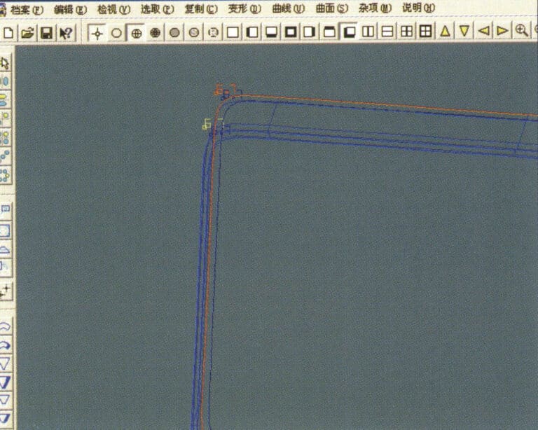
18. Dans le sens des aiguilles d'une montre, double-cliquez sur la troisième courbe/surface avec le bouton gauche de la souris pour créer une connexion ligne-surface
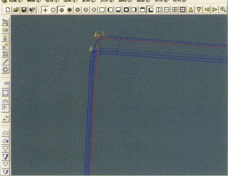
19. Continuez dans le sens des aiguilles d'une montre ; double-cliquez sur la quatrième courbe/surface avec le bouton gauche de la souris pour créer une connexion ligne-surface.
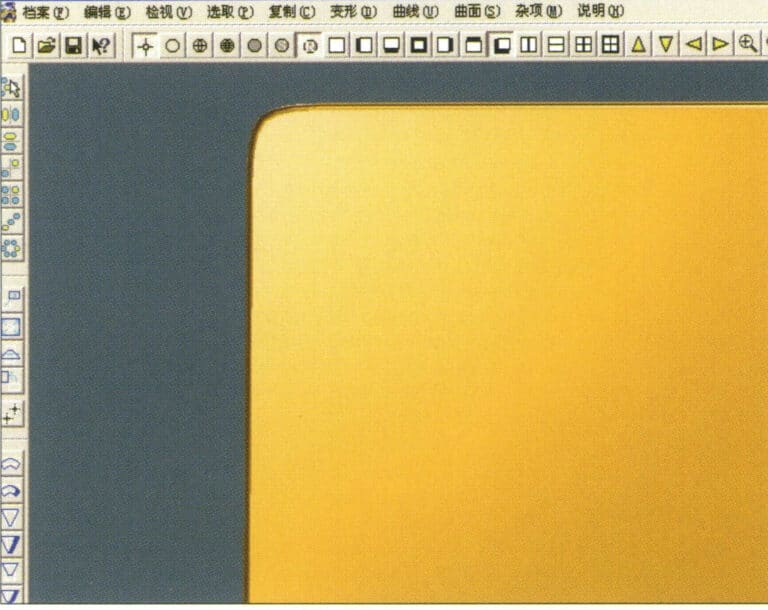
20. Select "View" > "Shadow Map" from the menu bar to inspect the shadow effects
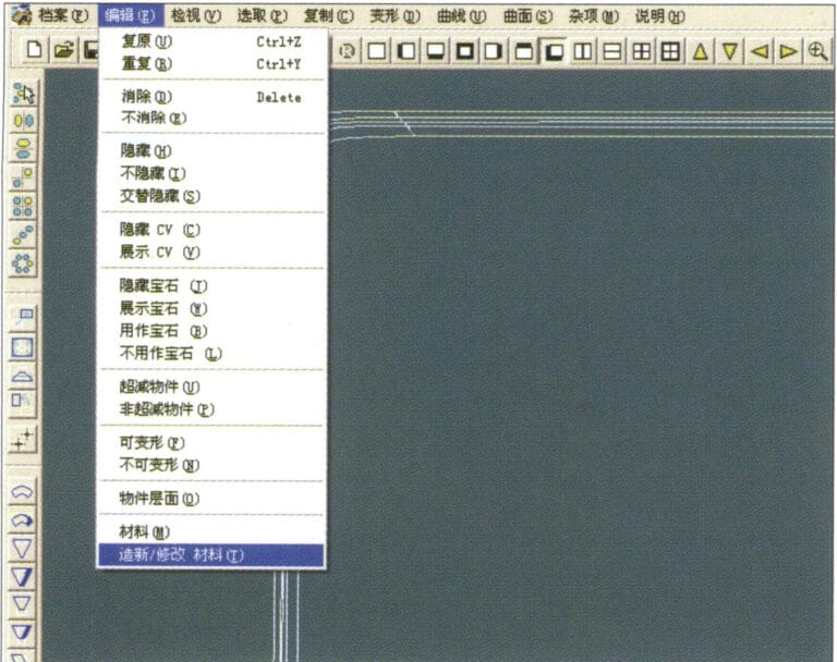
21. Select "Edit" > "Create/Modify Material" from the menu bar
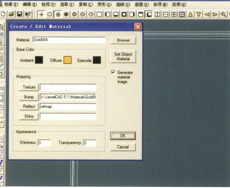
22. Entrez dans la boîte de dialogue "Créer/Modifier un matériau", saisissez les valeurs appropriées et confirmez.
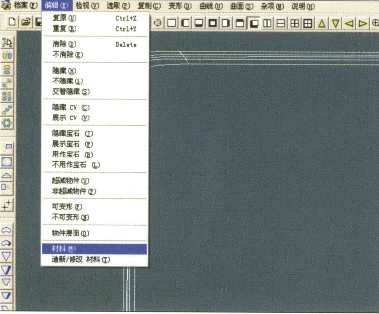
23. Select “Edit” > “Material” in the menu bar
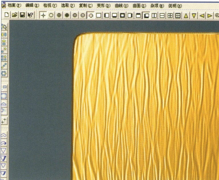
24. Select "View" > "Shadow Map" from the menu bar to examine the shadow effects
25. Select "File" > "Save As" from the menu bar to save the file
4. Finition guillochée
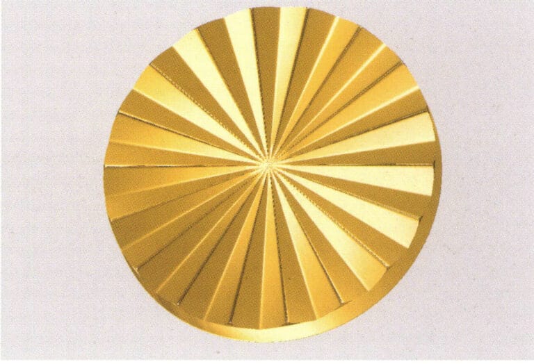

1. Create a new file in JewelCAD, select "Curve" > "Circular Curve" from the menu bar, enter the relevant values in the "Circular Curve" dialog box, and confirm
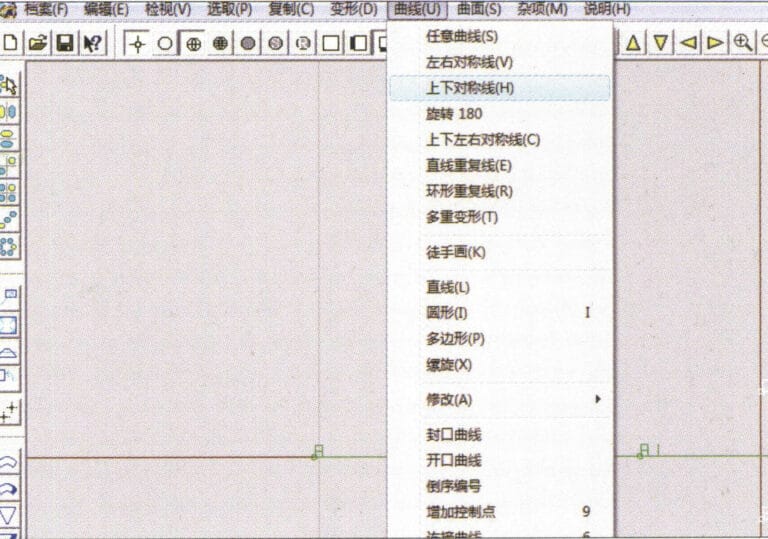
2. Select "Curve" > "Left-Right Symmetry Line" from the menu bar to draw a section
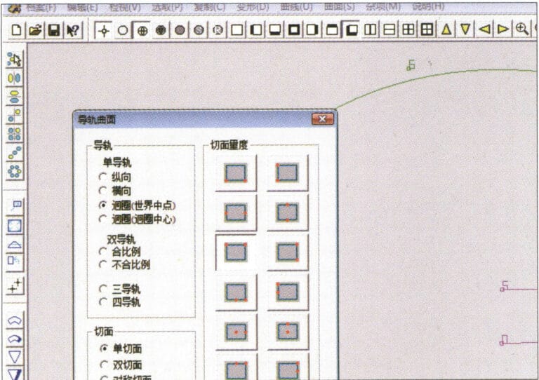
3. Select "Surface" > "Rail Surface" from the menu bar, enter "Rail Surface," select the relevant options and confirm; left-click on a curve as the section of the rail surface; left-click on another curve as the "Rail" > "Finish."

4. Select “View” > “Shadow Map” on the menu bar to view the light and shadow effects
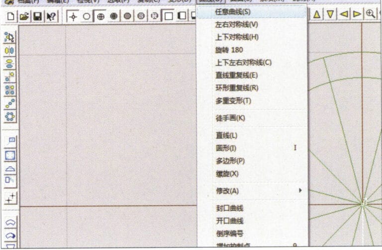
5. Select "Curve" > "Freefrom Curve" from the menu bar
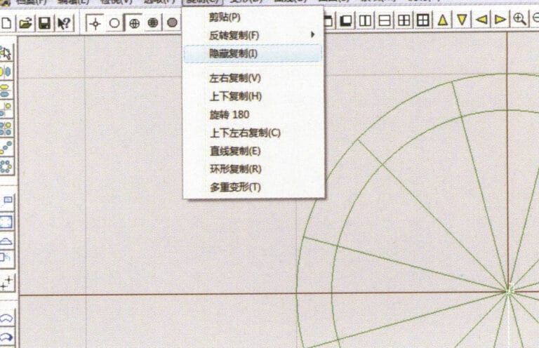
6. Select "Copy" > "Hide Copy" from the menu bar
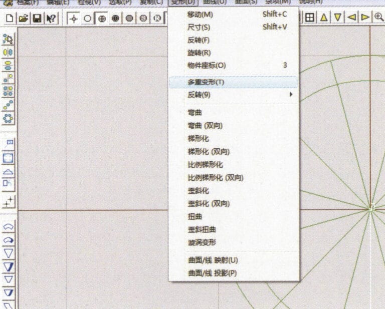
7. Select "Deformation" > "Multiple Deformation" from the menu bar
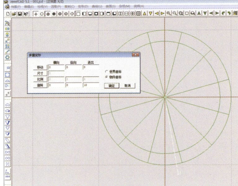
8. Entrez dans la boîte de dialogue "Déformation multiple" et saisissez les valeurs appropriées.
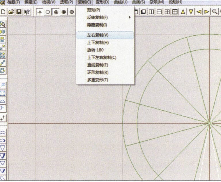
9. Select “Copy” > “Left/Right Copy” on the menu bar
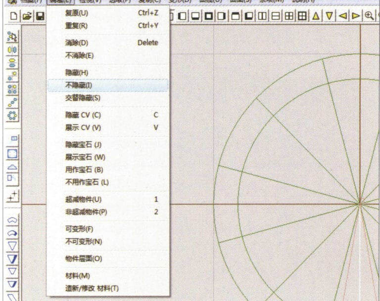
10. Select "Edit" > "Unhide" from the menu bar to display the hidden curves
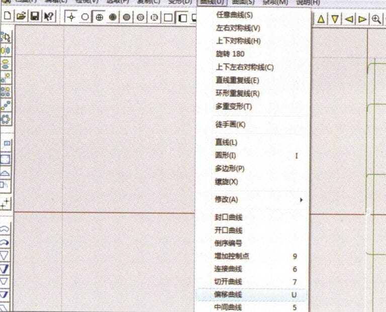
11. Select "Curve" > "Offset Curve" from the menu bar
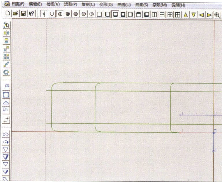
12. Select "Deformation" > "Move" from the menu bar to move the selected curve
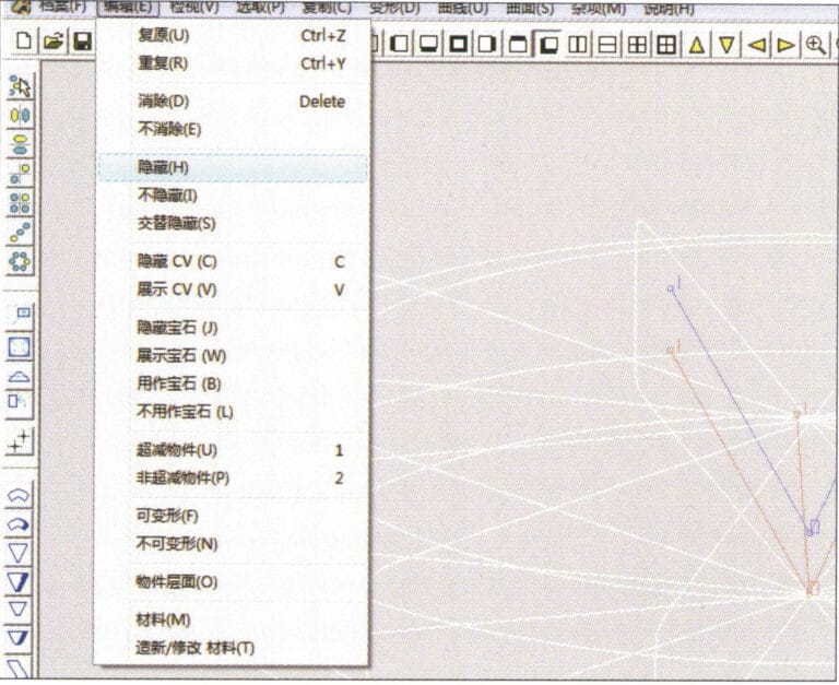
13. Select "Edit" > "Hide" from the menu bar to hide the circular surface
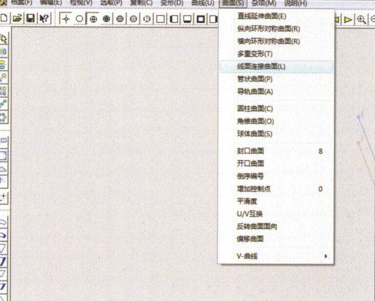
14. Select "Surface" > "Line Surface Connection Surface" from the menu bar

15. Sélectionnez les courbes/surfaces dans le sens des aiguilles d'une montre pour créer des connexions ligne-surface, puis sélectionnez dans la barre de menu
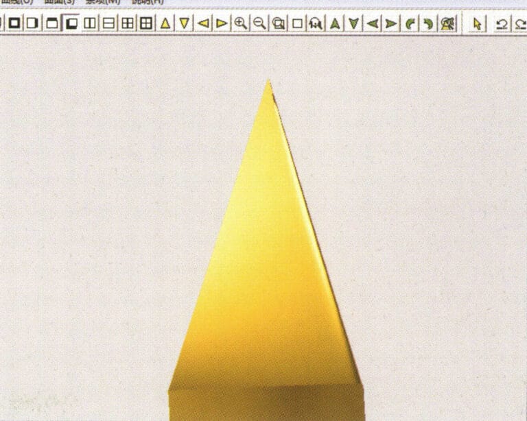
16. Select "View" > "Shadow Map" from the menu bar to inspect the shadow effects
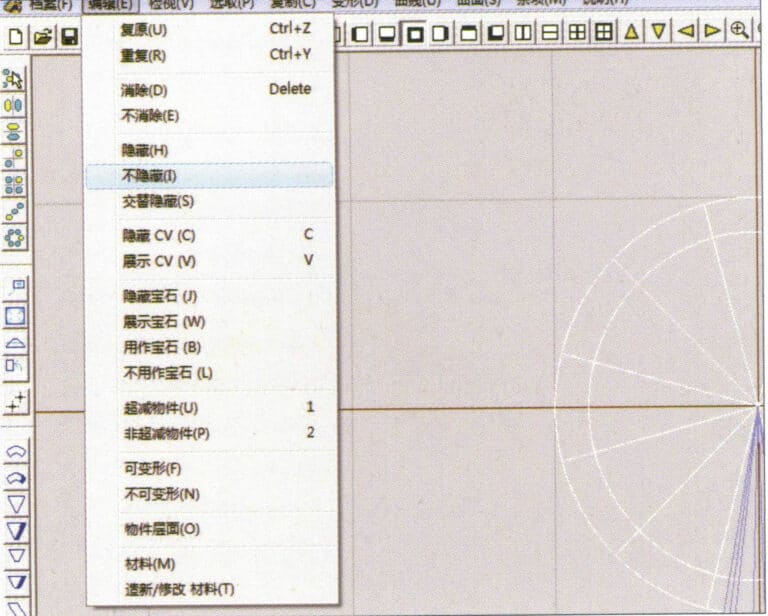
17. Select "Edit" > "Unhide" from the menu bar to display the hidden circular surfaces
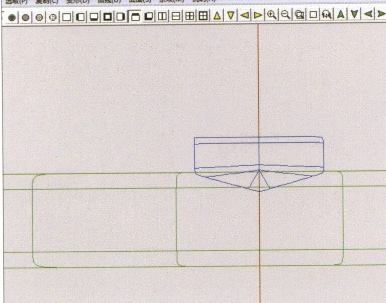
18. Select "Deformation" > "Move" from the menu bar to move the selected surface
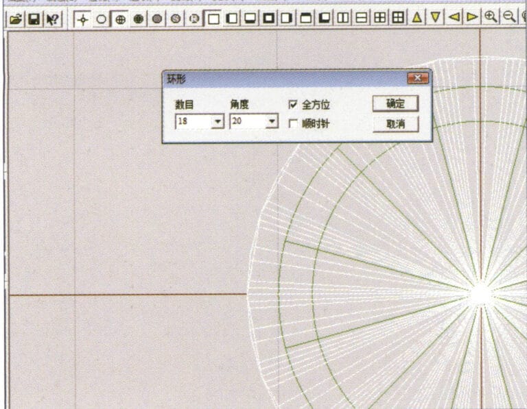
19. Select "Copy" > "Circular Copy" from the menu bar, enter the relevant values and confirm

20. Select “Miscellaneous” > “Boolean” > “Integrate” on the menu bar to integrate the selected surfaces.
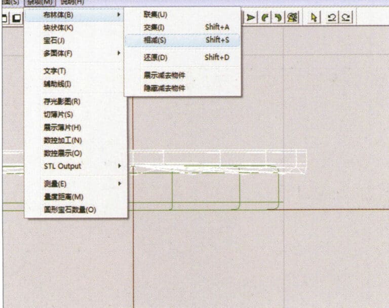
21. Select "Miscellaneous" > "Boolean" > "Subtract" from the menu bar to subtract the selected surface from the already united surface
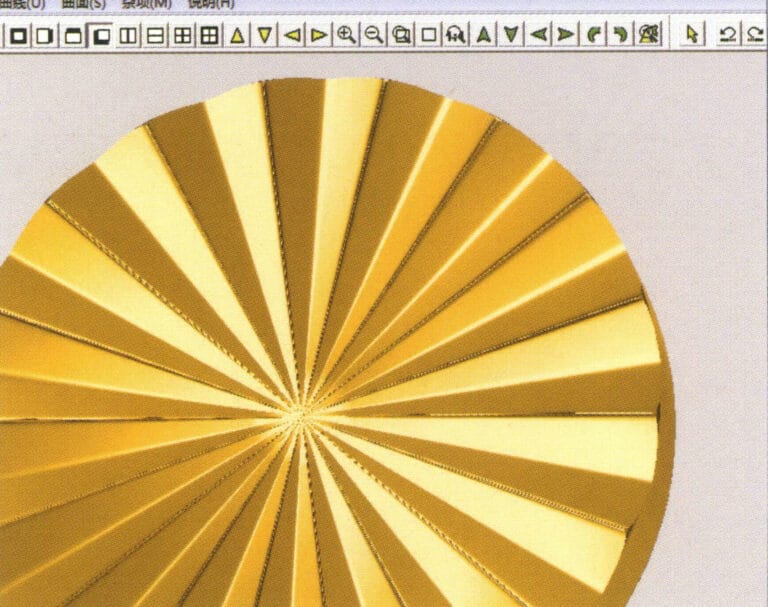
22. Select "View" > "Shadow Map" from the menu bar to inspect the shadow effects.
23. Select "File" > "Save File" from the menu bar to save the document
Section III Utilisation de JewelCAD pour créer des effets de bijoux
1. Bague à sertissage de diamants
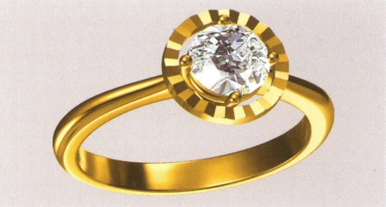
Les étapes de la production sont les suivantes :
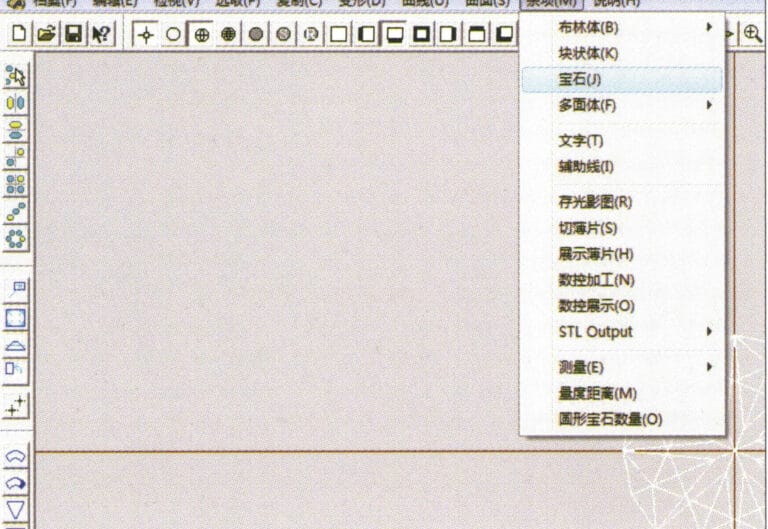
1. Create a new file in JewelCAD, select "Miscellaneous" > "Gem" from the menu bar

2. Select "Deformation" > "Multiple Deformation" from the menu bar
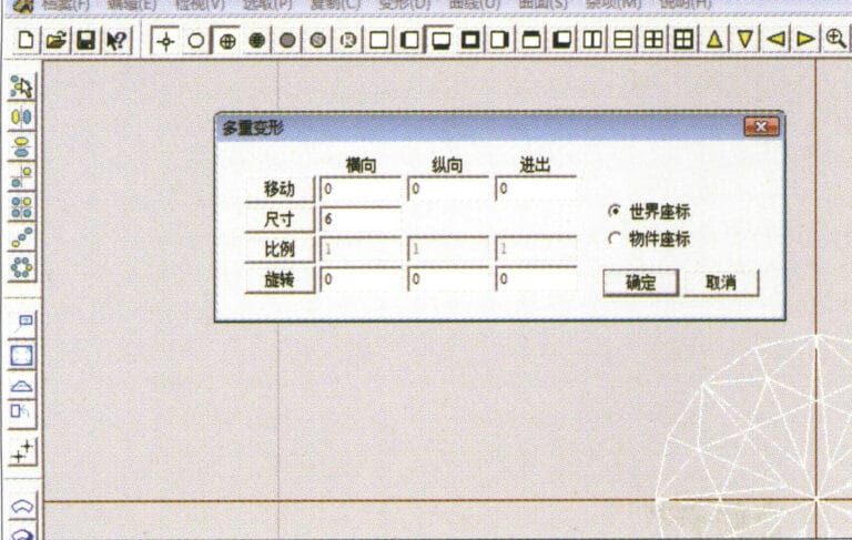
3. Entrez dans la boîte de dialogue "Déformation multiple", saisissez les valeurs appropriées et confirmez.
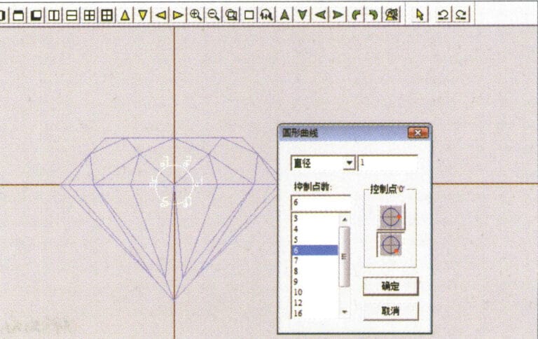
4. Select “Curve” > “Circular Curve” in the menu bar to enter the “Circular Curve” dialog box, enter the relevant values and confirm
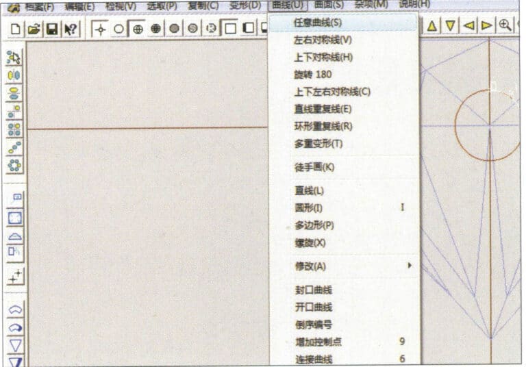
5. Select "Curve" > "Freeform Curve" from the menu bar to draw a claw-shaped guideline
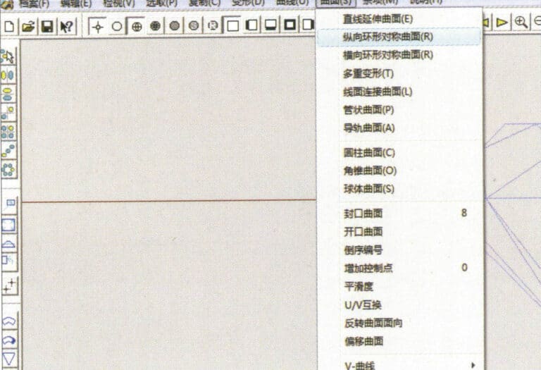
6. Select "Surface" > "Longitudinal Annular Symmetrical Surface" from the menu bar, and draw a claw shape
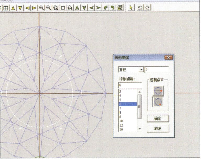
7. Select "Curve" > "Circular Curve" from the menu bar, enter the relevant values in the "Circular Curve" dialog box and confirm
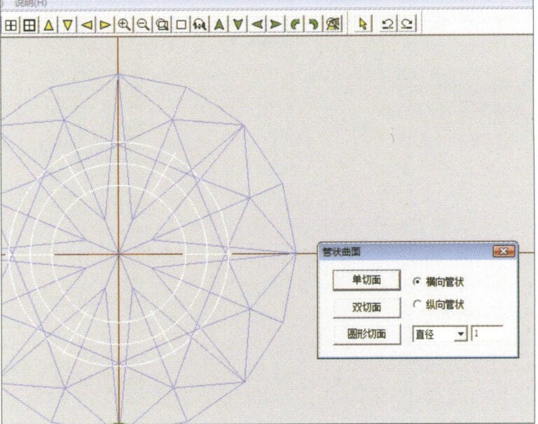
8. Select "Surface" > "Tubular Surface" from the menu bar, enter the relevant values and confirm
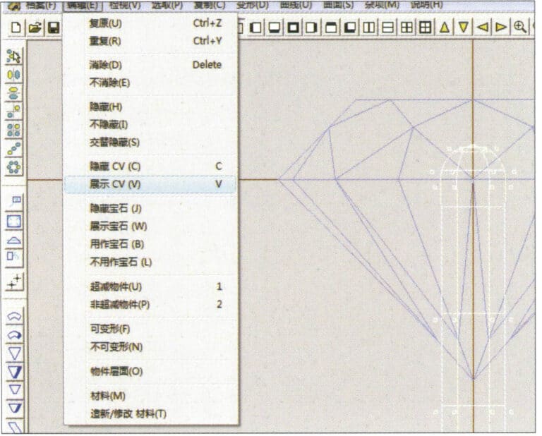
9. Select “Edit” > “Show CV” in the menu bar
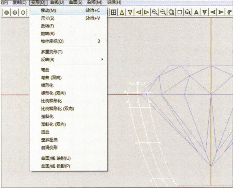
10. Select “Deformation” > “Move” in the menu bar to move the CV
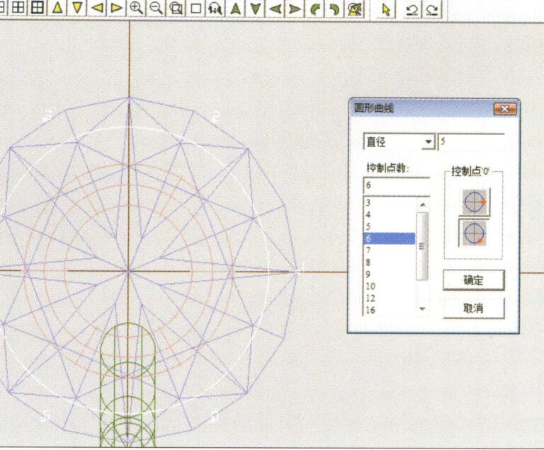
11. Select "Curve" > "Circular Curve" from the menu bar, enter the relevant values in the "Circular Curve" dialog box and confirm
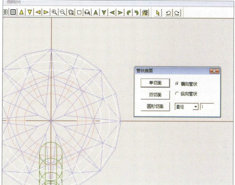
12. Select "Surface" > "Tubular Surface" from the menu bar, enter the relevant values and confirm
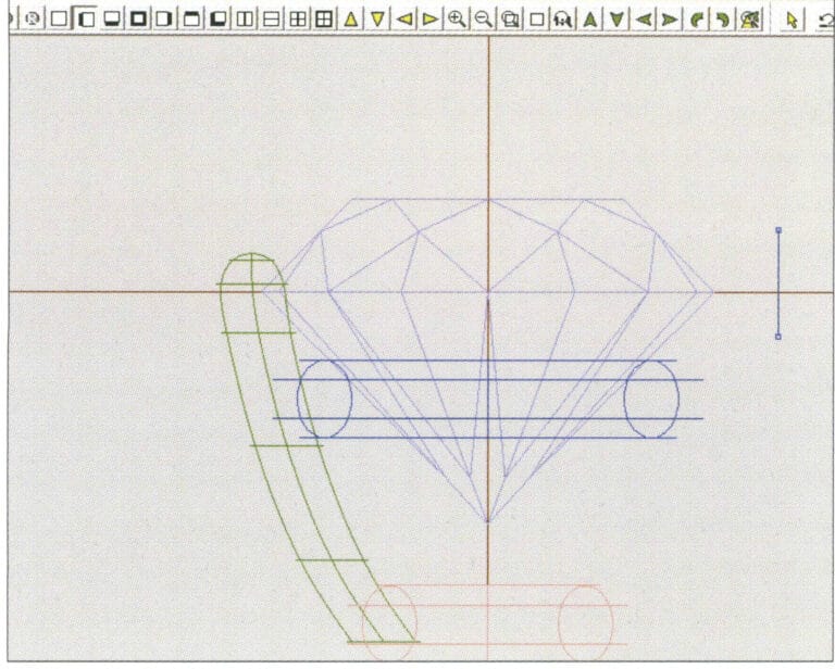
13. Select the menu bar "Edit" > "Move" to move the selected graphic

14. Select the completed claw shape, choose "Copy" > "Circular Copy" from the menu, enter the relevant values in the "Circular Copy" dialog box and confirm
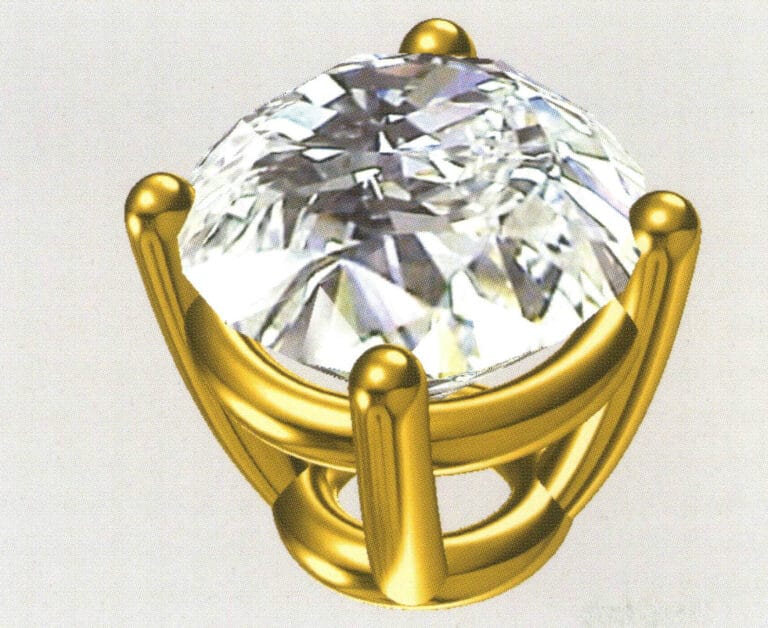
15. Select "View" > "Shadow Map" from the menu bar to inspect the shadow effects
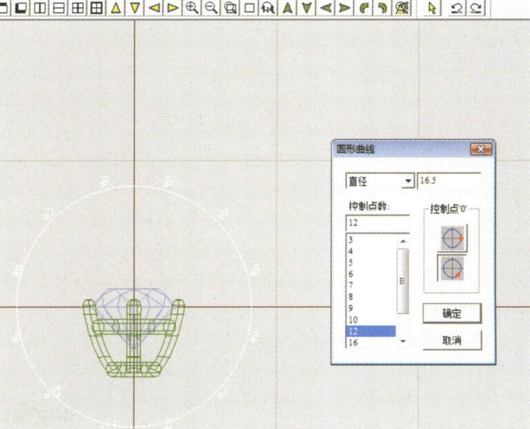
16. Select "Curve" > "Circular Curve" from the menu bar, enter the "Circular Curve" dialog box, and input the relevant values as the inner diameter of the ring shank
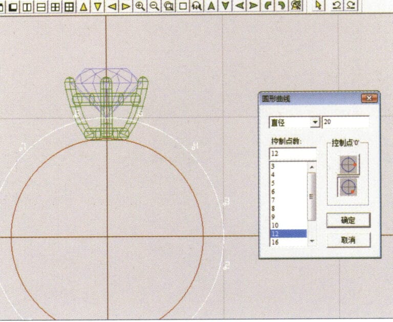
17. Select "Curve" > "Circular Curve" from the menu bar, enter the "Circular Curve" dialog box, and input the relevant values as the outer diameter of the ring shank

18. Select "Curve" > "Circular Curve" from the menu bar, enter the "Circular Curve" dialog box, and input the relevant values as the outer diameter of the engine-turned band
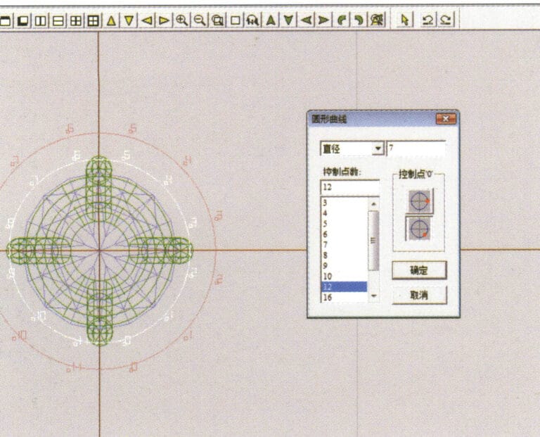
19. Select "Curve" > "Circular Curve" from the menu bar, enter the "Circular Curve" dialog box, and input the relevant values as the inner diameter of the engine-turned band
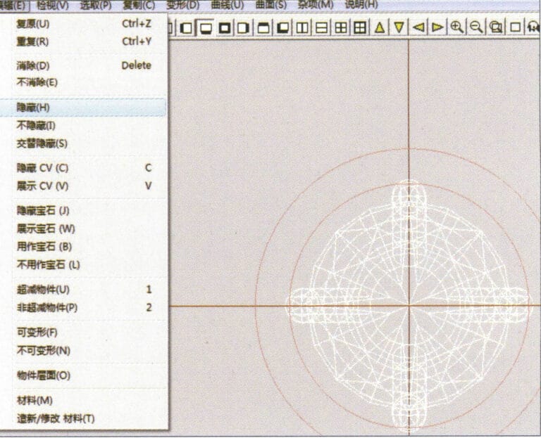
20. Select "Edit" > "Hide" from the menu bar to hide the completed gemstone inlay
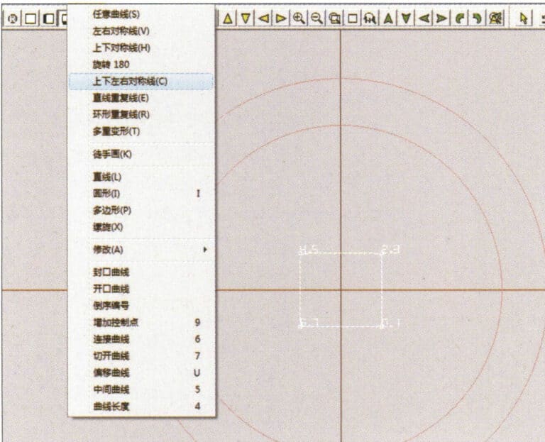
21. Select "Curve" > "Vertical and Horizontal Symmetry Line" from the menu bar
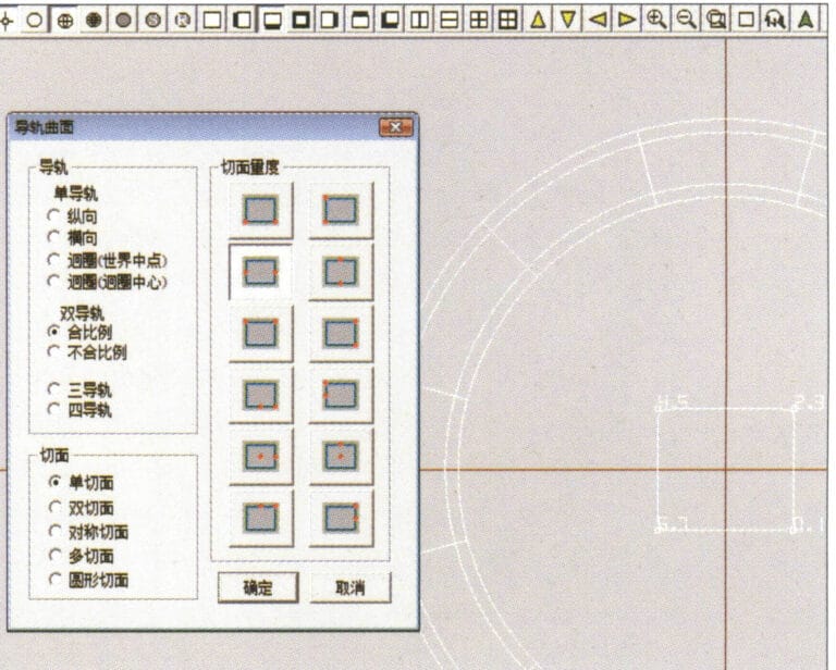
22. Select "Surface" > "Rail Surface" from the menu bar to enter the "Rail Surface" dialog box, select the relevant options and confirm
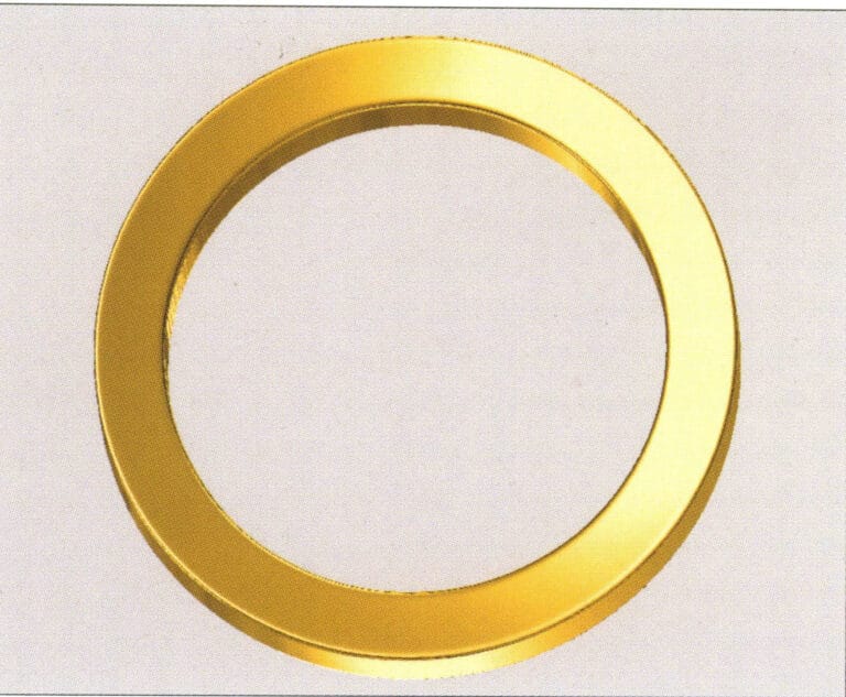
23. Select "View" > "Shadow Map" from the menu bar to inspect the shadow effects
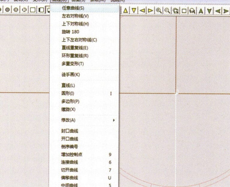
24. Select "Curve" > "Freeform Curve" from the menu bar to draw a guideline

25. Select "Copy" > "Hide Copy" from the menu bar to copy the already drawn auxiliary lines
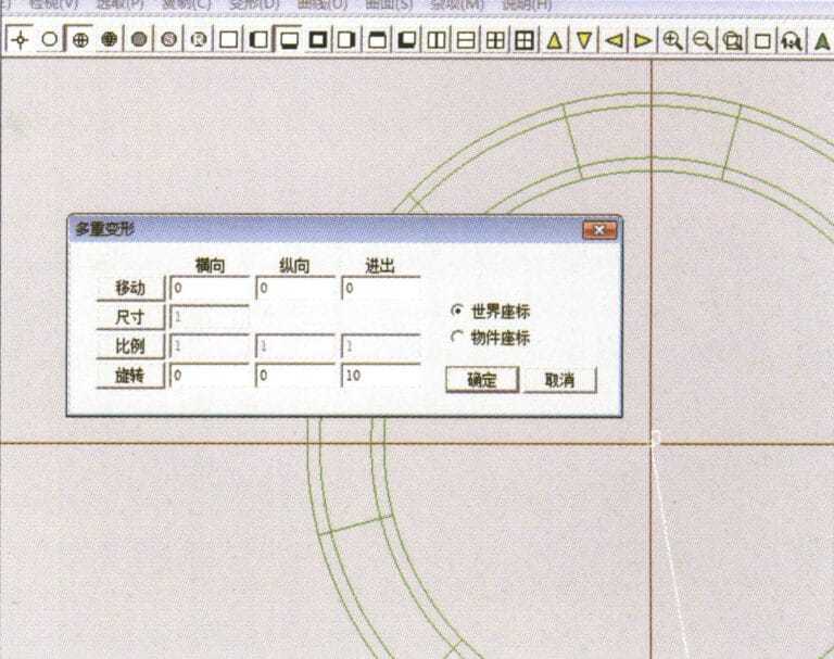
26. Select “Deformation” > “Multiple Deformation” in the menu bar to enter the “Multiple Deformation” dialog box, enter the relevant values and confirm
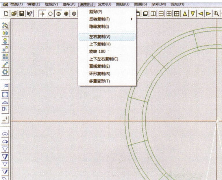
27. Select “Copy” > “Copy Up and Down” in the menu bar to copy the drawn auxiliary lines
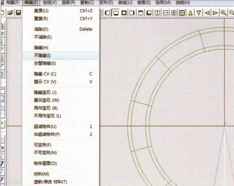
28. Select "Edit" > "Unhide" from the menu to display the hidden curves
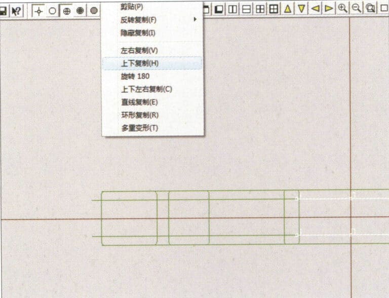
29. Select "Copy" > "Copy Up and Down" from the menu bar to copy the selected curve
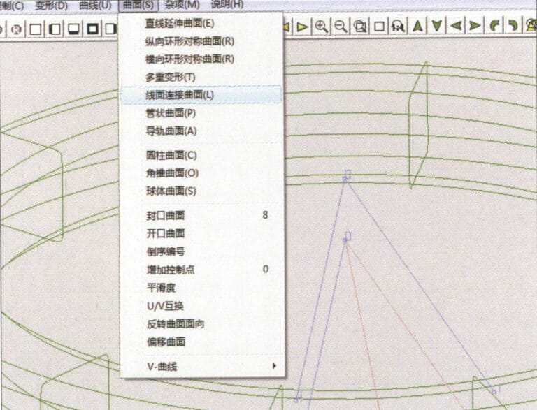
30. Select curves/surfaces in a clockwise direction to create line-surface connections, then select "Surface" > "Cap Surface" from the menu bar
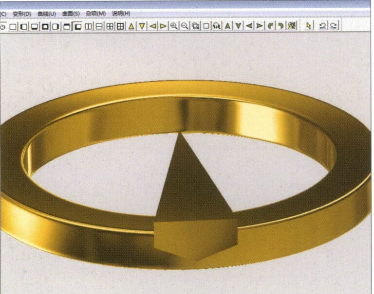
31. Select "View" > "Shadow Map" from the menu bar to inspect the shadow effects
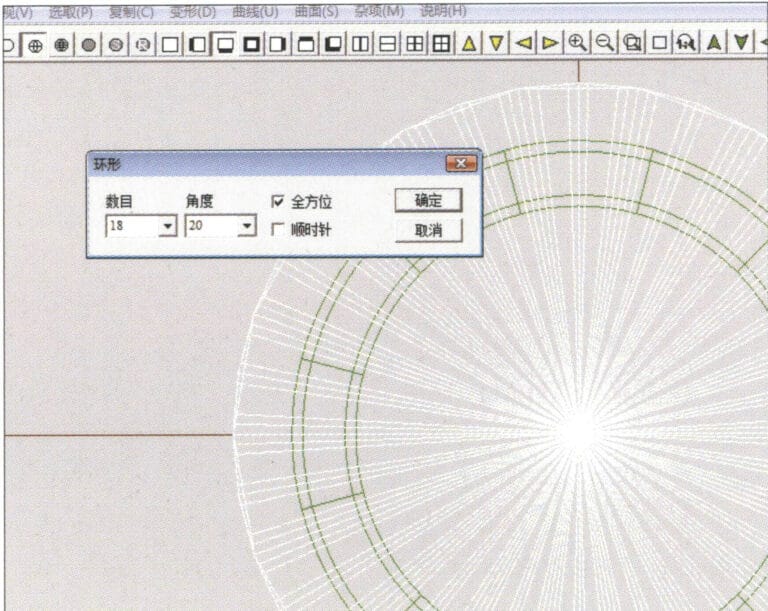
32. Select "Copy" > "Circular Copy" from the menu bar, enter the relevant values and confirm
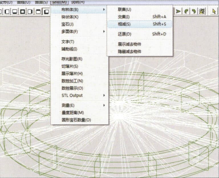
33. Select "Miscellaneous" > "Boolean" > "Subtract" from the menu bar to subtract the selected surface from the already united surface
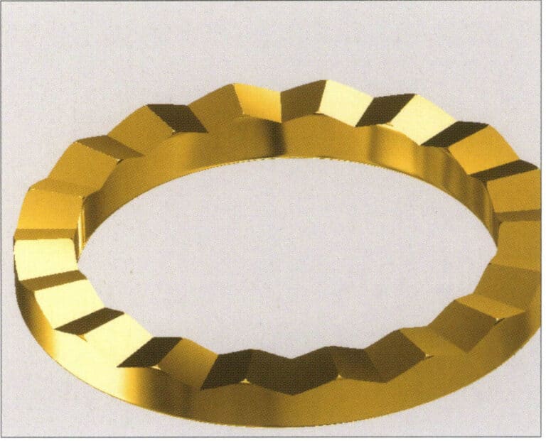
34. Select "View" > "Shadow Map" from the menu bar to inspect the shadow effects
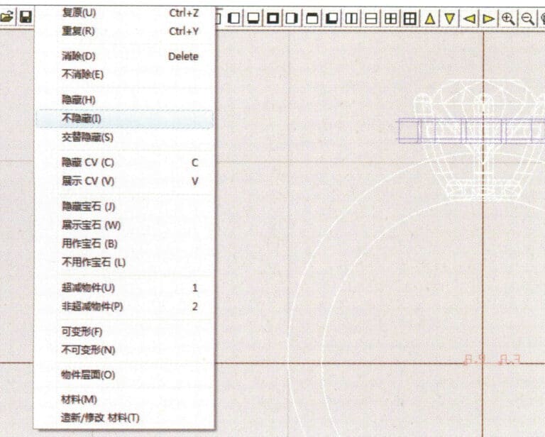
35. Select "Edit" > "Unhide" from the menu bar to display the hidden objects
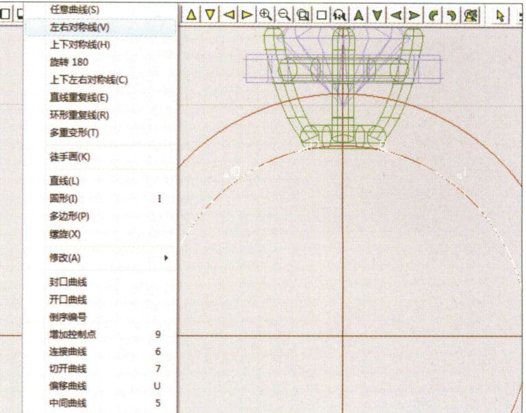
36. Select "Curve" > "Left-Right Symmetry Line" from the menu bar to draw the inner diameter of the ring wall
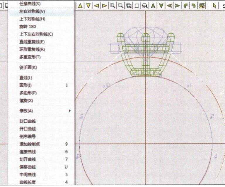
37. Select "Curve" > "Left-Right Symmetry Line" from the menu bar to draw the outer diameter of the ring wall
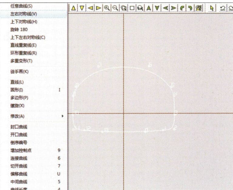
38. Select “Curve” > “Left-Right Symmetry Line” in the menu bar to draw a cutout of the ring shank
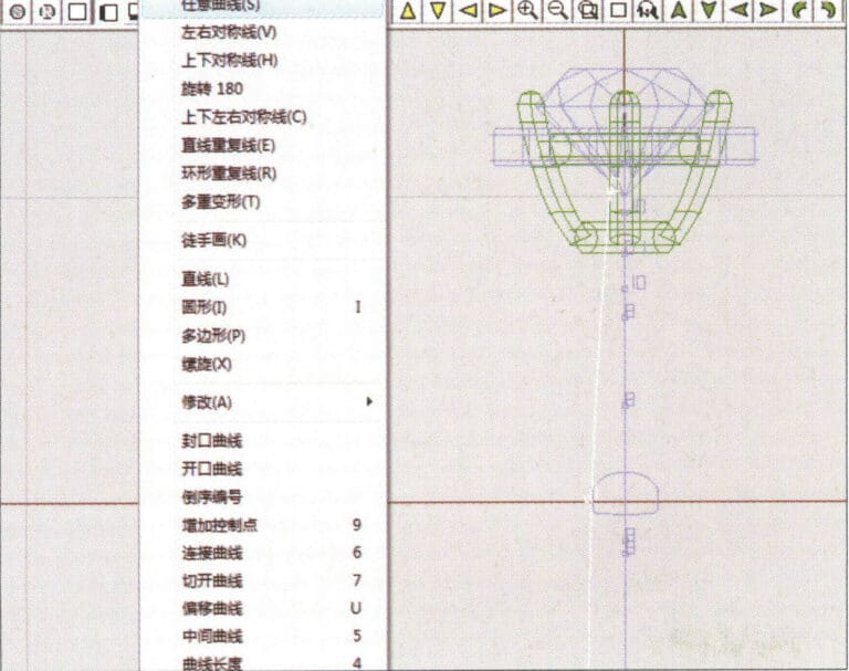
39. Select "Curve" > "Freeform Curve" from the menu bar to draw a guideline
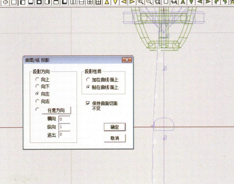
40. Select "Deformation" > "Surface/Line Projection" from the menu bar to enter the "Surface/Line Projection" dialog box, input the relevant values and confirm
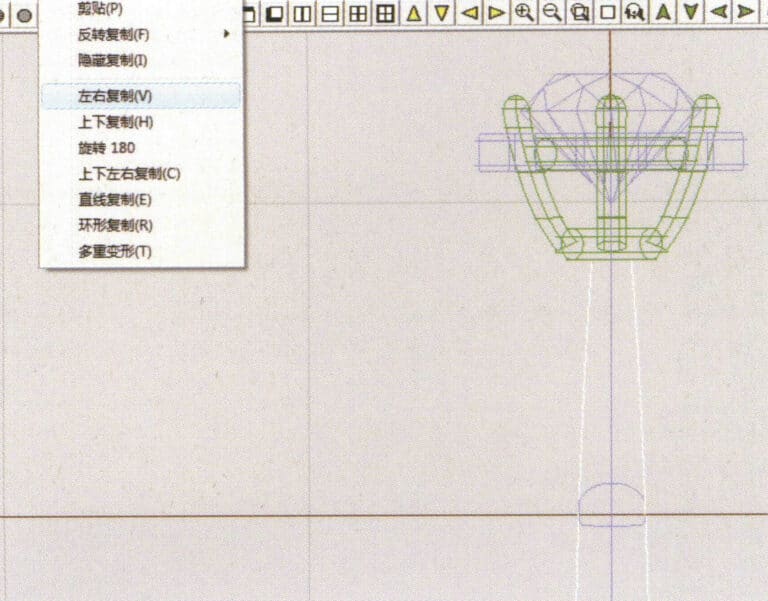
41. Select "Copy" > "Copy Left and Right" from the menu bar to copy the inner diameter of the ring shank
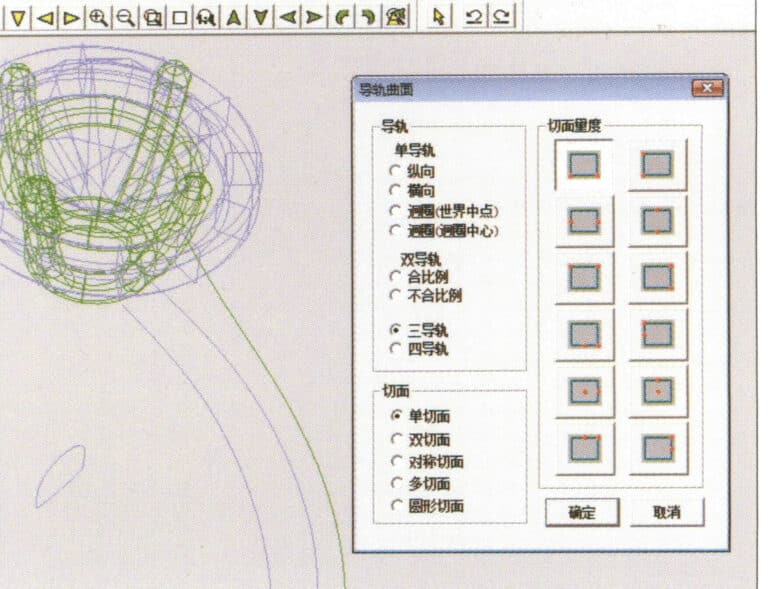
42. Select "Surface" > "Rail Surface" from the menu bar to enter the "Rail Surface" dialog box, select the relevant options and confirm
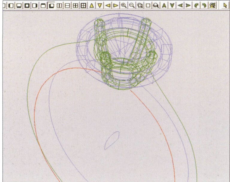
43. Sélectionnez une courbe comme rail de guidage gauche, puis sélectionnez une courbe comme rail de guidage droit.

44. Sélectionner une courbe comme rail de guidage supérieur
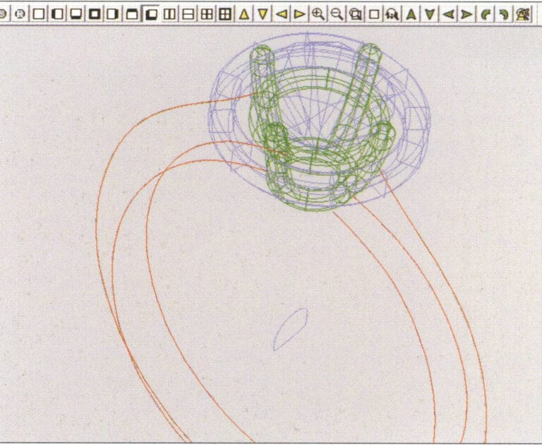
45. Sélectionnez une courbe comme section transversale de la surface de guidage.
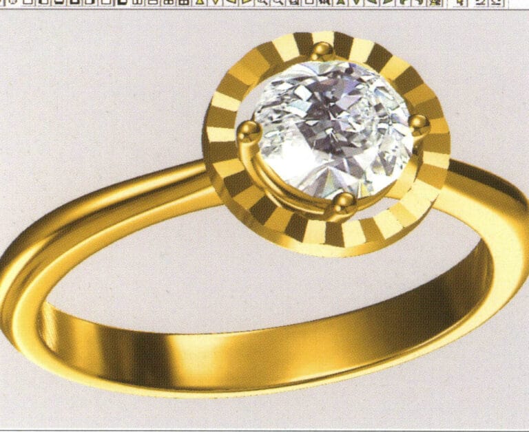
46. Select "View" > "Light and Shadow Map" from the menu bar to examine the light and shadow effects
47. Select "File" > "Save As" from the menu bar to save the file
Copywrite @ Sobling.Jewelry - Fabricant de bijoux sur mesure, usine de bijoux OEM et ODM
2. Anneau de perles

Les étapes de la production sont les suivantes :
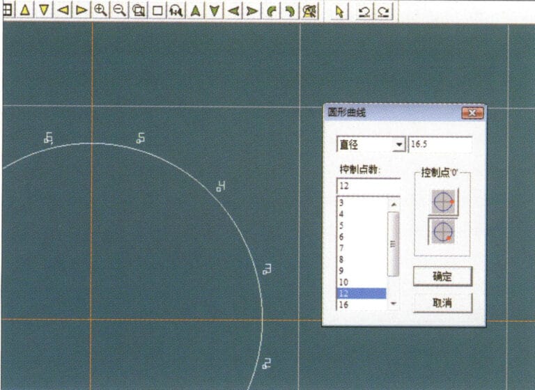
1. Create a new file in JewelCAD, select "Curve" > "Circular Curve" from the menu bar, enter the relevant values in the "Circular Curve" dialog box as the outer curve of the ring, and confirm
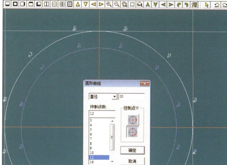
2. Select "Curve" > "Circular Curve" from the menu bar, enter the relevant values in the "Circular Curve" dialog box to set the inner curve of the ring, and confirm
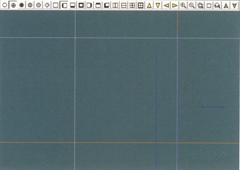
3. Select "Edit" > "Move" from the menu bar to move the selected inner curve of the ring
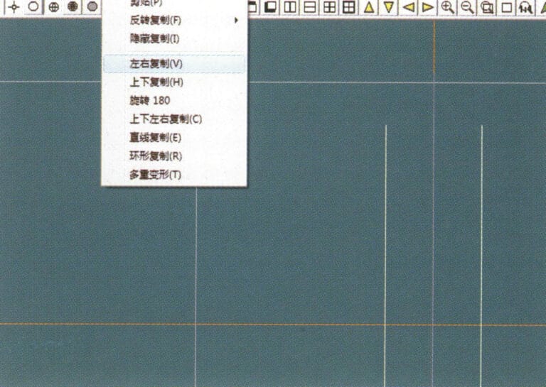
4. Select "Copy" > "Copy Left and Right" from the menu bar to copy the curve of the inner circle of the ring
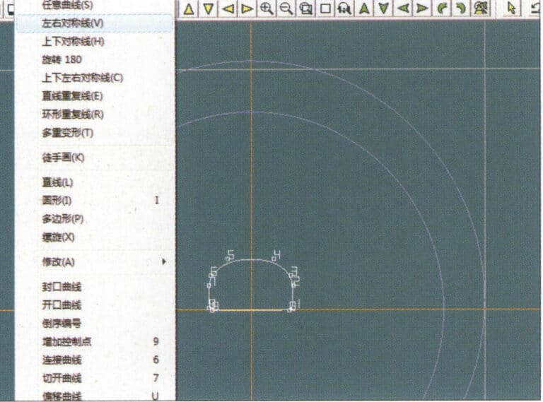
5. Select "Curve" > "Left-Right Symmetry Line" from the menu bar as the cross-section of the ring band
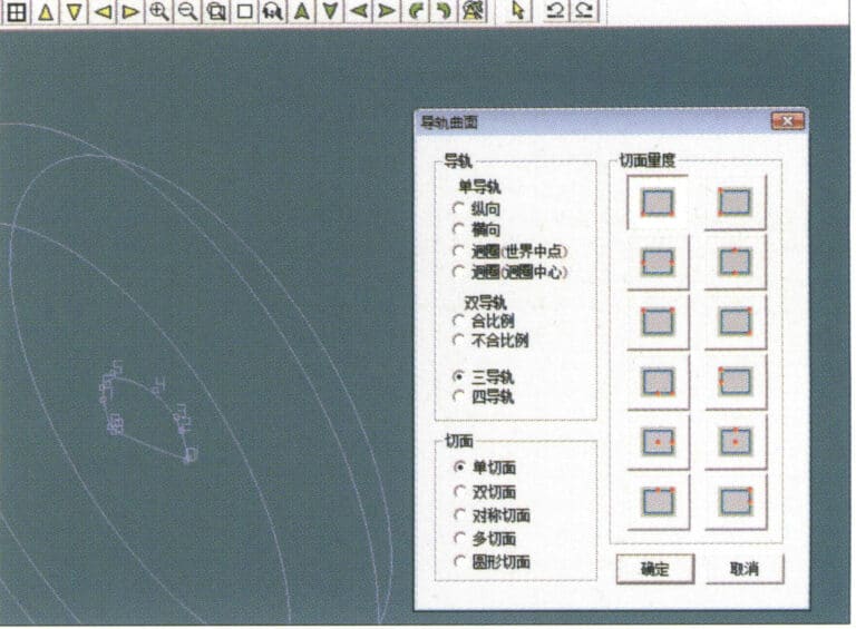
6. Select "Curved Surface" > "Guide Rail Surface" from the menu bar, enter the "Guide Rail Surface" dialog box, select the relevant options and confirm
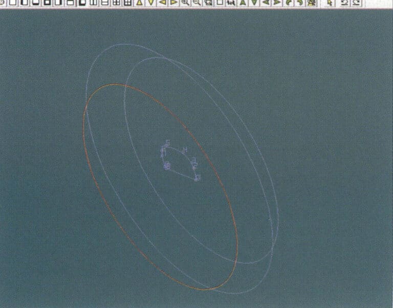
7. Choisir une courbe comme rail de guidage
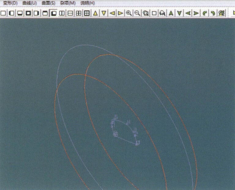
8. Choisir une courbe comme rail de guidage supérieur
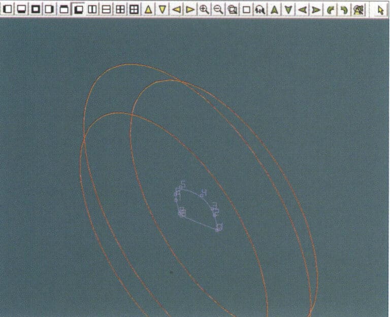
9. Choisir la section transversale de l'anneau comme section transversale de la surface de la courbe de guidage.
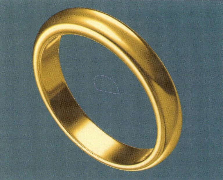
10. Select "View" > "Shadow Map" from the menu bar to inspect the shadow effects
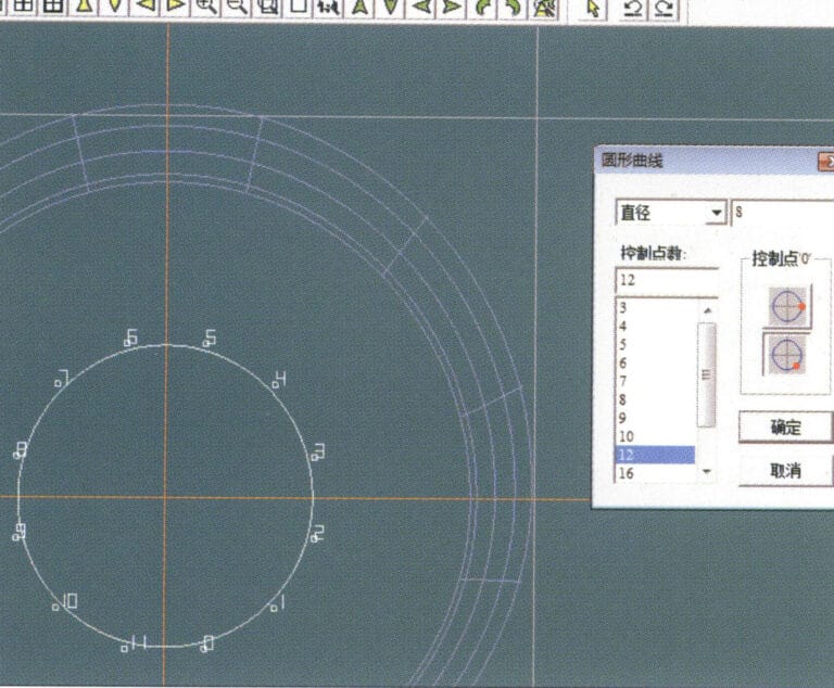
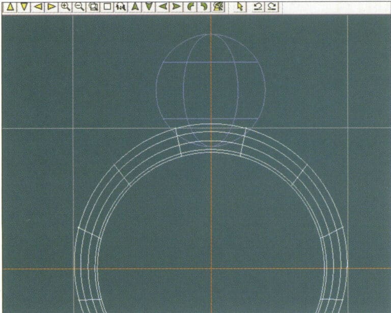
11. Select "Curve" > "Circular Curve" from the menu bar, enter the relevant values in the "Circular Curve" dialog box as auxiliary lines, and confirm
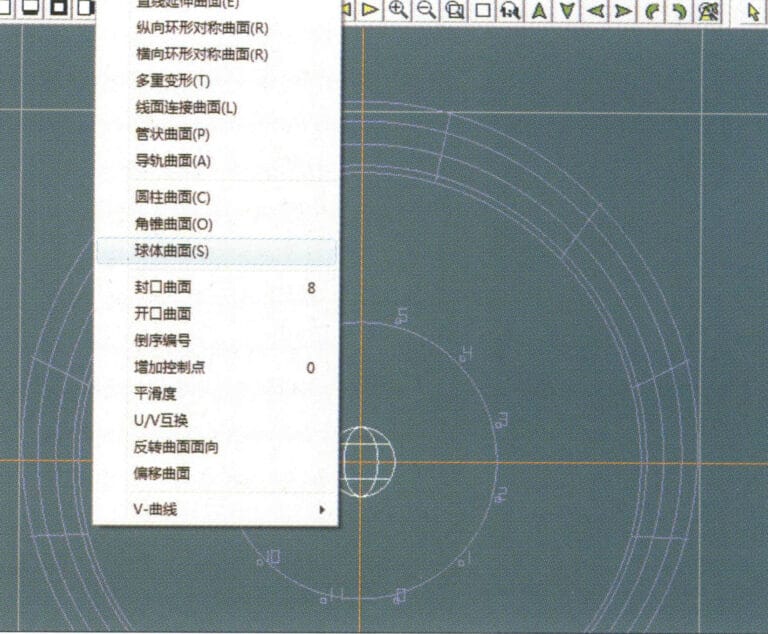
12. Select "Surface" > "Spherical Surface" from the menu bar
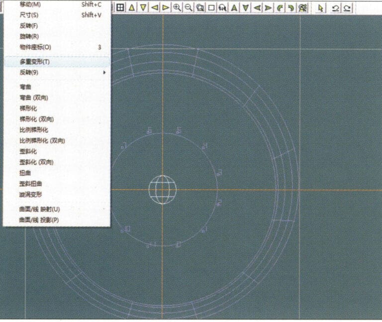
13. Select "Deformation" > "Multiple Deformation" from the menu bar to enlarge the sphere
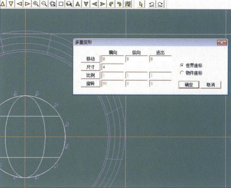
14. Entrez dans la boîte de dialogue "Déformation multiple", saisissez les valeurs correspondantes pour agrandir la sphère jusqu'à la largeur des lignes directrices et confirmez
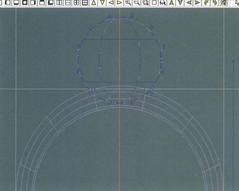
15. Select "Edit" > "Move" from the menu bar to move both the sphere and the auxiliary line simultaneously
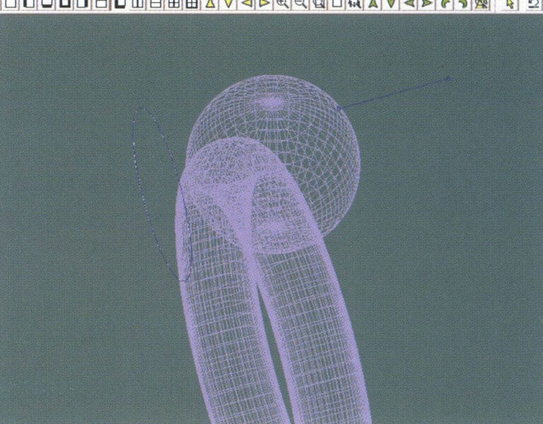
16. Select "Edit" > "Move" from the menu bar to remove the guidelines
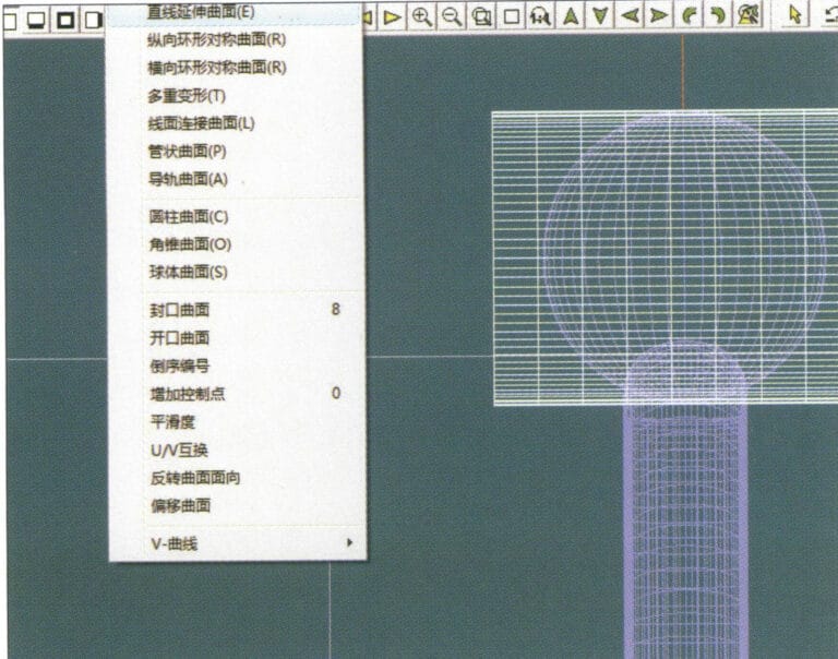
17. Select "Surface" > "Straight Line Extend Surface" from the menu bar to extend the auxiliary line into an auxiliary surface
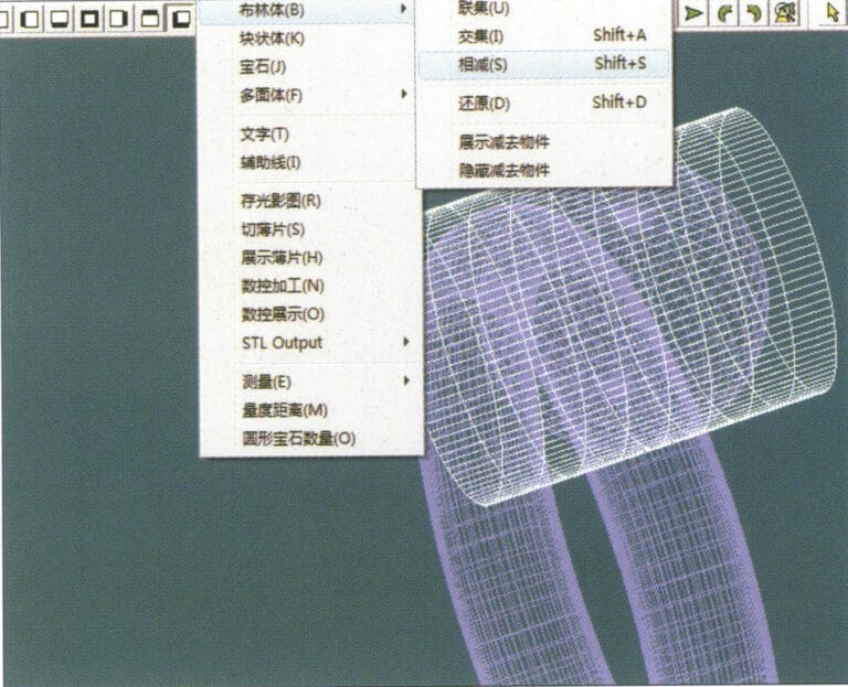
18. Select "Miscellaneous" > "Boolean" > "Subtract" from the menu bar to subtract the corresponding parts of the auxiliary surface ring
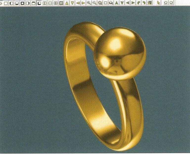
19. Select "View" > "Shadow Map" from the menu bar to inspect the shadow effects
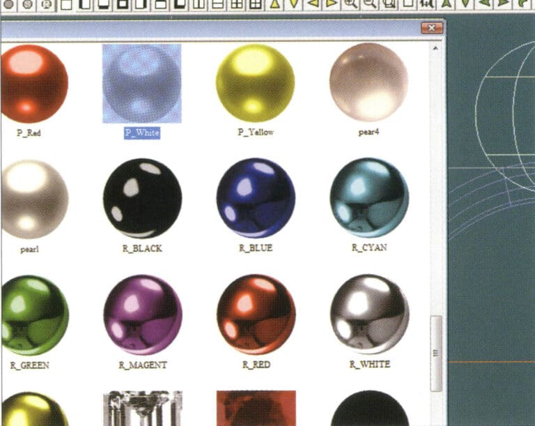
20. Select the sphere, go to the menu bar and choose "Edit" > "Materials", enter the "Materials" dialog box, select the white pearl material and confirm
21. Select the ring band, then choose "Edit" > "Materials" from the menu bar
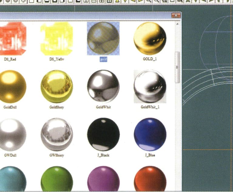
22. Entrez dans la boîte de dialogue "Matériaux", sélectionnez le matériau approprié et confirmez.
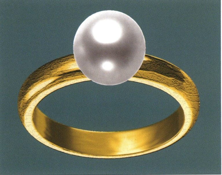
23. Select "View" > "Shadow Map" from the menu bar to examine the light and shadow effects
24. Select "File" > "Save As" from the menu bar to save the file
3. Pendentif en or noir rehaussé de diamants

Les étapes de la production sont les suivantes :
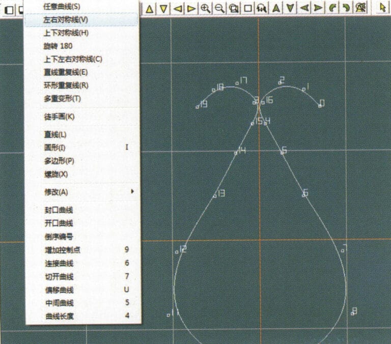
1. Create a new file in JewelCAD, select "Curve" > "Left-Right Symmetrical Line" from the menu bar, and draw the inner contour line of the pendant
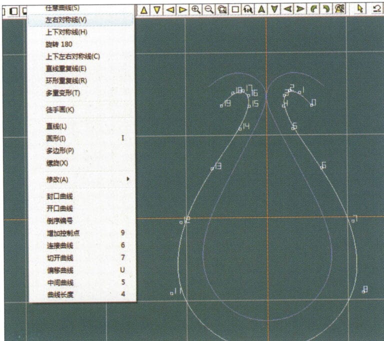
2. Select "Curve" > "Left-Right Symmetrical Line" from the menu bar to draw the outer contour line of the pendant (note that the control points of the inner contour line and the outer contour line should have the same direction and quantity).
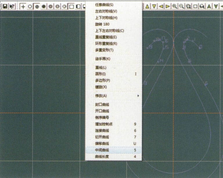
3. Select "Curve" > "Middle Curve" from the menu bar
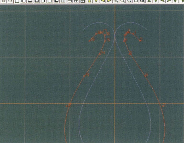
4. Sélectionnez deux courbes pour créer la courbe du milieu. Sélectionnez d'abord la ligne de contour extérieure
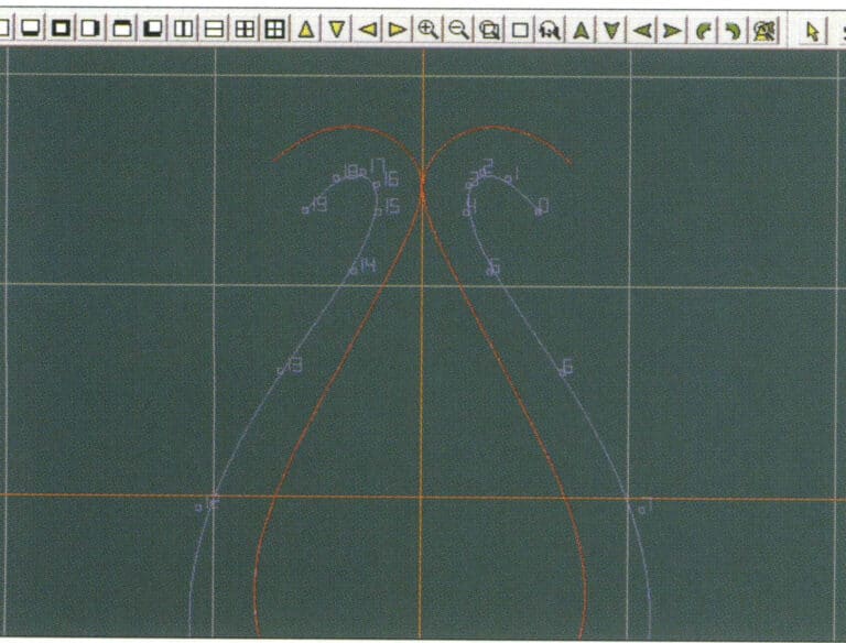
5. Sélectionnez deux courbes pour créer la courbe du milieu, puis sélectionnez la ligne de contour intérieure
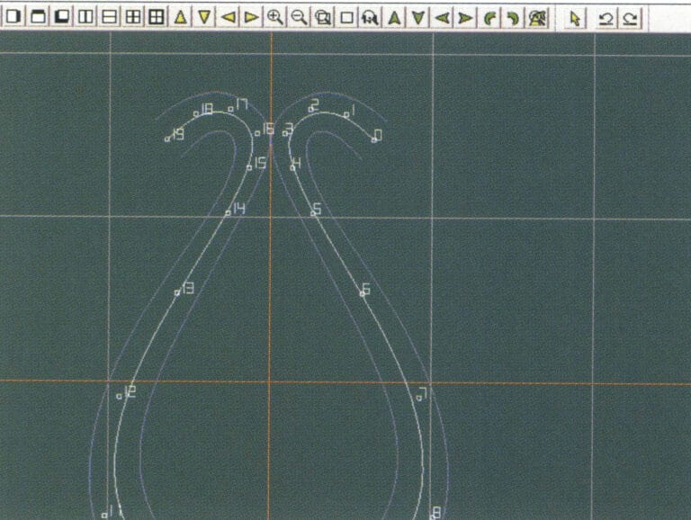
6. Visualiser les courbes intermédiaires déjà créées
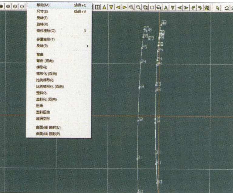
7. Select "Deformation" > "Move" from the menu bar to move the CV and the CV of the contour line
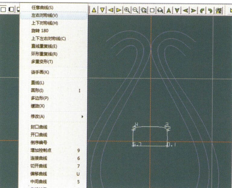
8. Select "Curve" > "Left-Right Symmetry Line" from the menu bar to create a cross-section
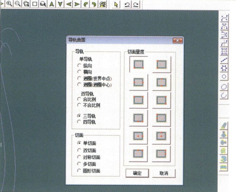
9. Select "Surface" > "Rail Surface" from the menu bar, enter the "Rail Surface" dialog box to select the relevant options, and confirm; select a curve as the left curve, starting from the left curve in a clockwise direction, left-click on the curve as the rail, and then select another curve as the section of the rail surface
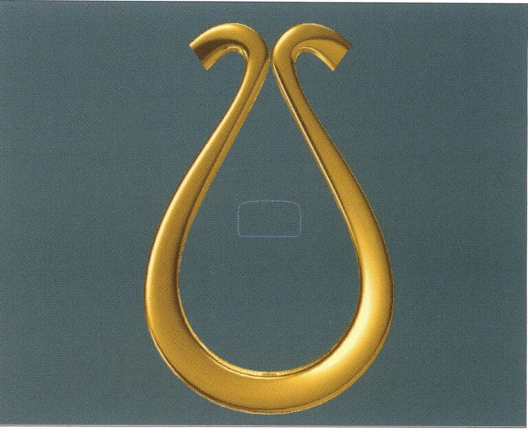
10. Select "View" > "Shadow Map" from the menu bar to inspect the shadow effects
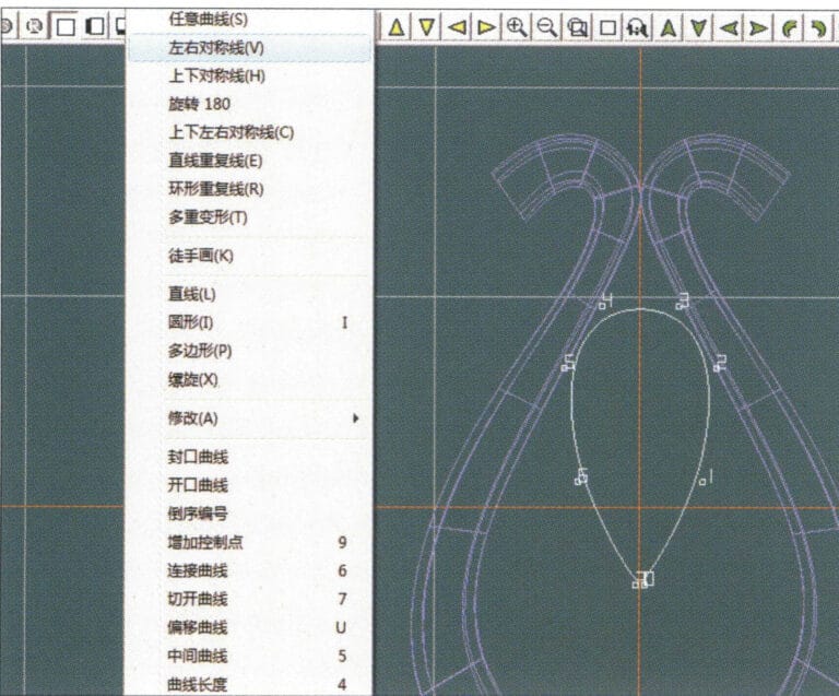
11. Select "Curve" > "Left-Right Symmetry Line" from the menu bar to draw the outer contour line of the seed-shaped toggle
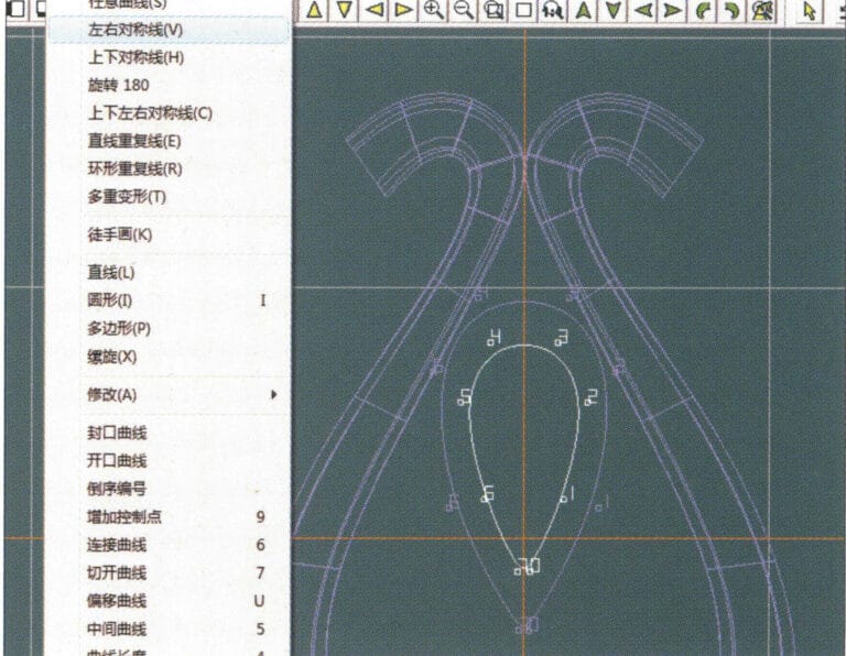
12. Select "Curve" > "Left-Right Symmetry Line" from the menu bar to draw the inner contour line of the seed-shaped toggle
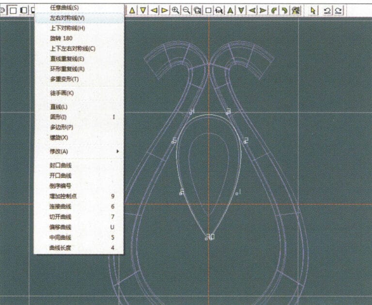
13. Select "Curve" > "Left-Right Symmetry Line" from the menu bar, and draw the lower dark line of the center of the seed-shaped toggle
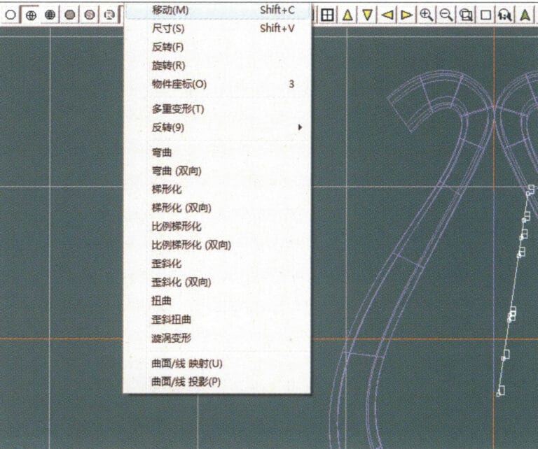
14. Select "Deformation" > "Move" from the menu bar to move the seed-shaped toggle CV
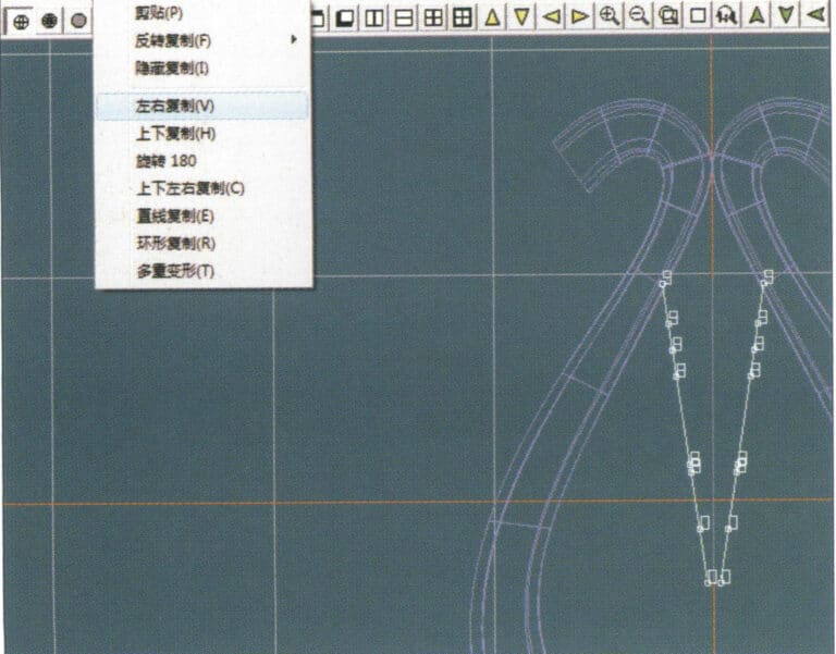
15. Select "Copy" > "Copy Left and Right" from the menu bar to copy the curve of the seed-shaped toggle
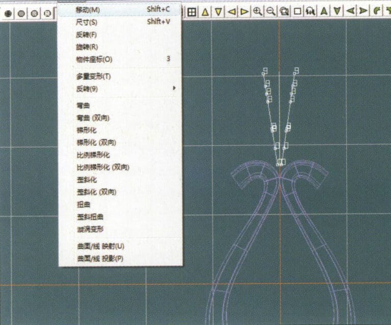
16. Select "Deformation" > "Move" from the menu bar to move the melon seed buckle curve
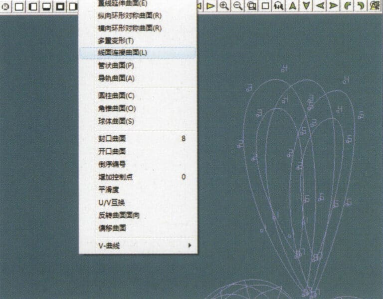
17. Select "Surface" > "Line-Surface Connection Surface" from the menu bar, and select the curve/surface in a clockwise direction to create a line-surface connection surface, then select "Curve" > "Closed Surface" from the menu bar
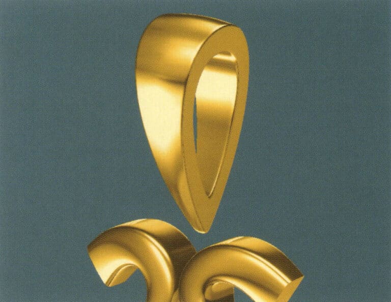
18. Select "View" > "Shadow Map" from the menu bar to examine the shadow effects
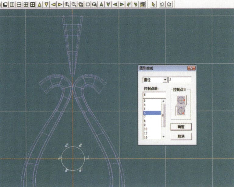
19. Select "Curve" > "Circular Curve" from the menu bar, enter the relevant values and confirm

20. Select "Surface" > "Tubular Surface" from the menu bar
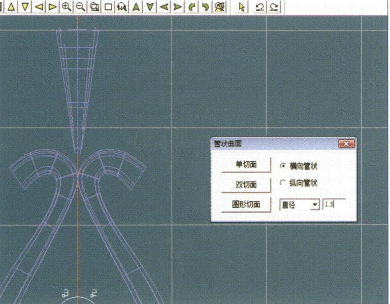
21. Entrez dans la boîte de dialogue "Surface tubulaire", saisissez les valeurs pertinentes, cliquez sur la section circulaire et confirmez.
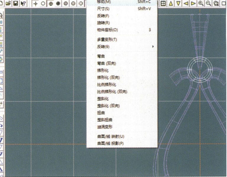
22. Select "Deformation" > "Move" from the menu bar to move the ring buckle

23. Select "File" > "Insert File" from the menu bar
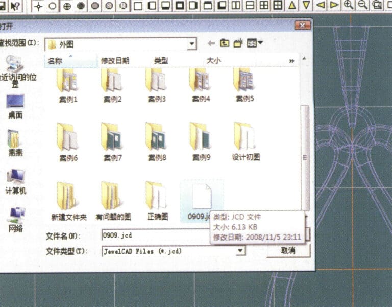
24. Dans la boîte de dialogue "Insérer un fichier", sélectionnez le document souhaité et confirmez.
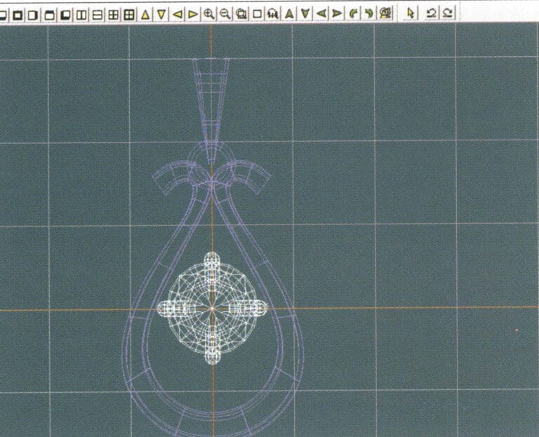
25. Voir le fichier inséré - Gemstone
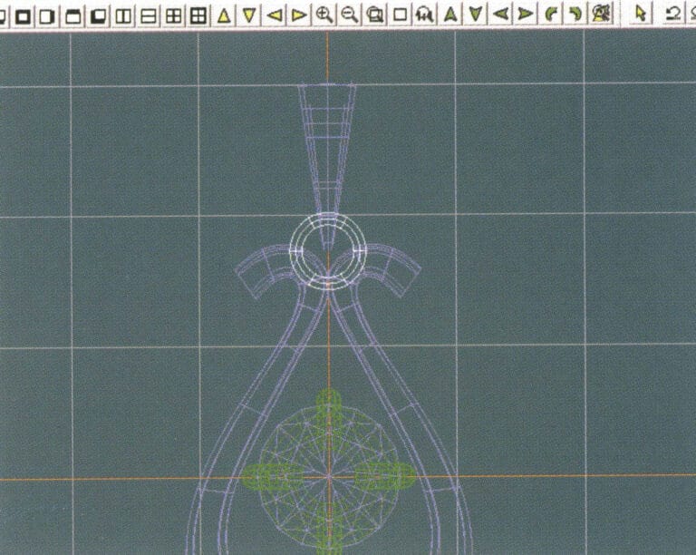
26. Select "Copy" > "Copy Up and Down" from the menu bar to copy the selected toggle
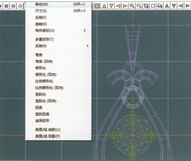
27. Select "Deformation" > "Move" from the menu bar to move the horizontal ring toggle
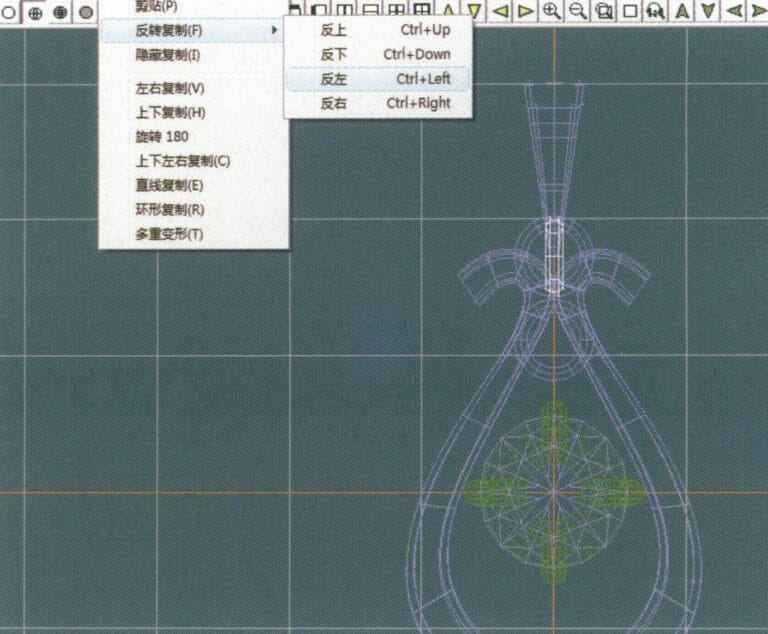
28. Select "Copy" > "Reverse Copy" > "Reverse Left" from the menu bar to create a vertical ring toggle
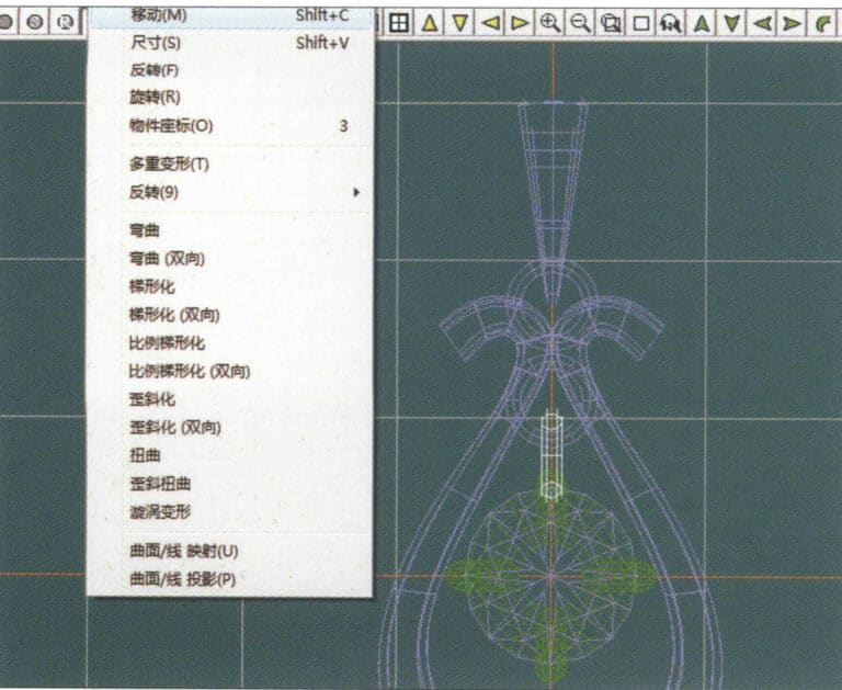
29. Select "Deformation" > "Move" from the menu bar to move the horizontal ring toggle
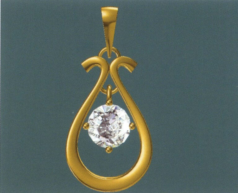
30. Select "View" > "Shadow Map" from the menu bar to examine the light and shadow effects
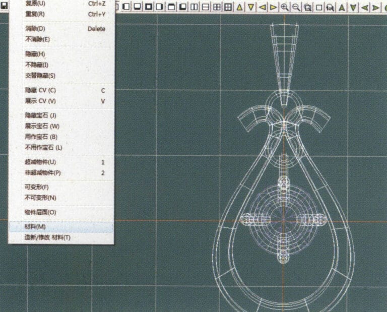
31. Select "Edit" > "Materials" from the menu bar to modify the materials of the selected object
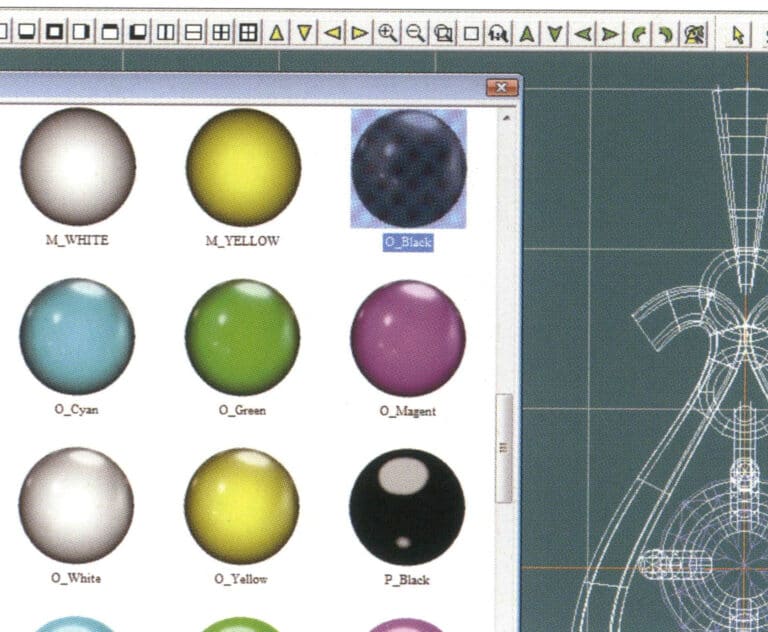
32. Entrez dans la boîte de dialogue "Matériaux", sélectionnez l'or noir et confirmez.
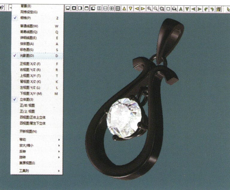
33. Select "View" > "Shadow Map" from the menu bar to inspect the shadow effects
34. Select "File" > "Save As" from the menu bar to save the file
4. Pendentif en rubis
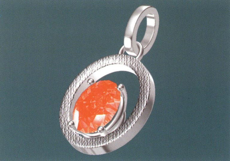
Les étapes de la production sont les suivantes :
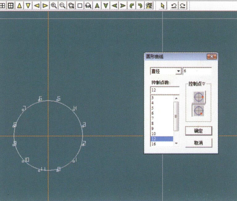
1. Create a new file in JewelCAD, select "Curve" > "Circular Curve" from the menu bar, enter the relevant values in the "Circular Curve" dialog box as the inner auxiliary line, and confirm

2. Select "Curve" > "Circular Curve" from the menu bar, enter the relevant values in the "Circular Curve" dialog box as the external auxiliary line, and confirm
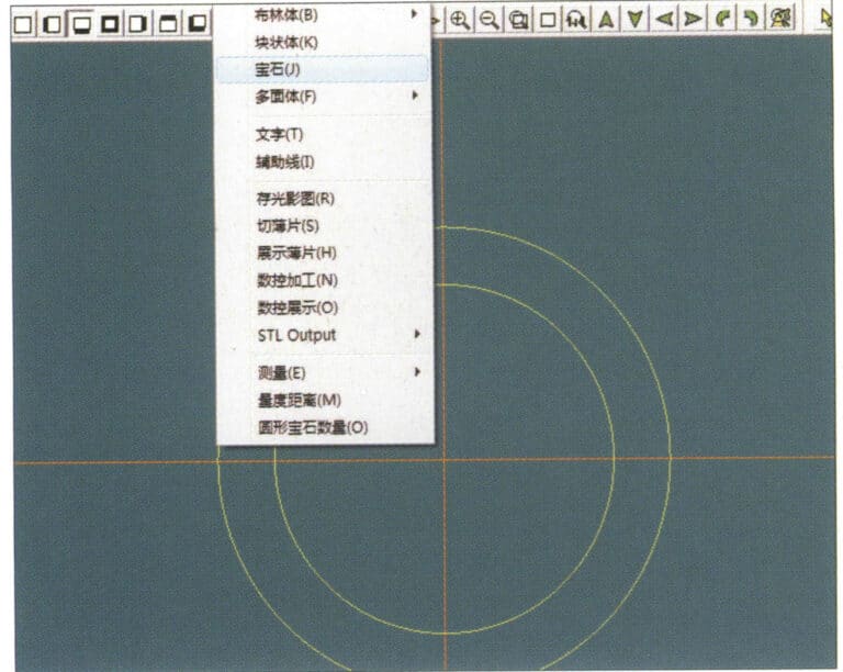
3. Select "Miscellaneous" > "Gemstones" from the menu bar
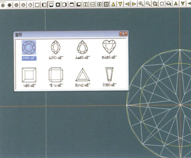
4. Entrez dans la boîte de dialogue "Gem", sélectionnez les gemmes concernées et confirmez.
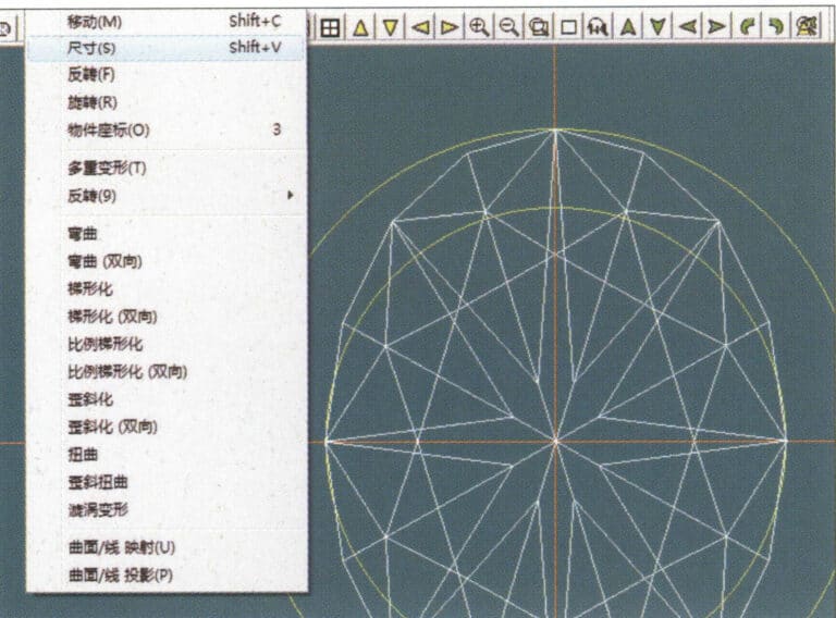
5. Select "Deformation" > "Size" from the menu bar to change the round gemstone into an oval gemstone
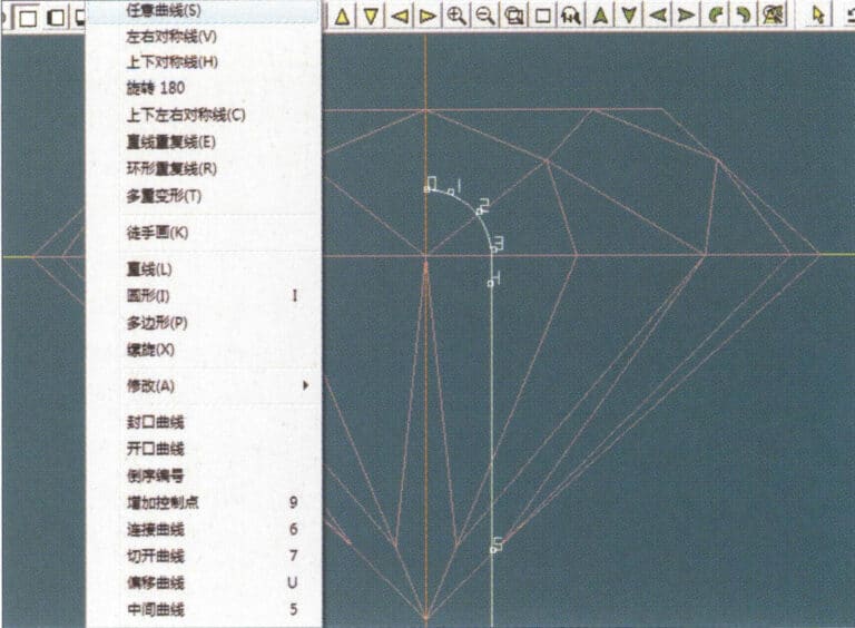
6. Select "Curve" > "Freeform Curve" from the menu bar to draw a claw-shaped guideline
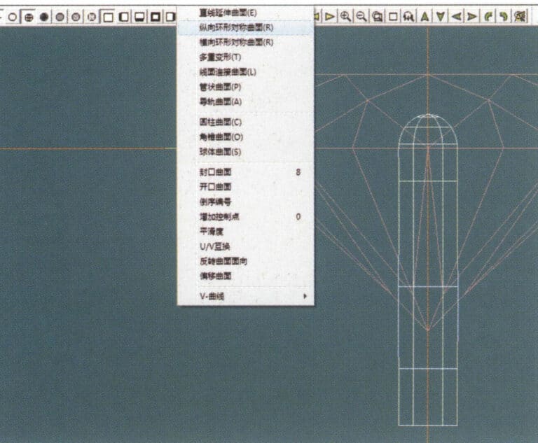
7. Select "Surface" > "Longitudinal Circular Symmetrical Surface" from the menu bar, and draw a claw shape
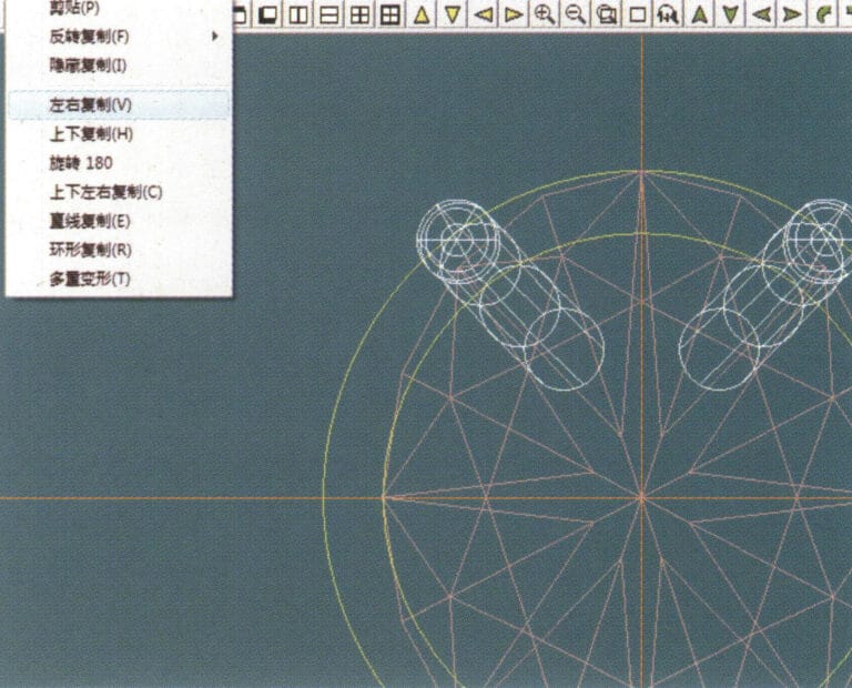
8. Select "Copy" > "Copy Left and Right" from the menu bar to copy the claw shape
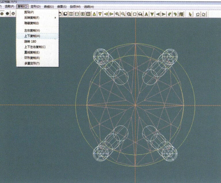
9. Select "Copy" > "Copy Up and Down" from the menu bar to copy the claw shape again
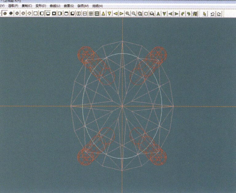
10. Select "Deformation" > "Size" from the menu bar to change the circular guideline to an elliptical guideline
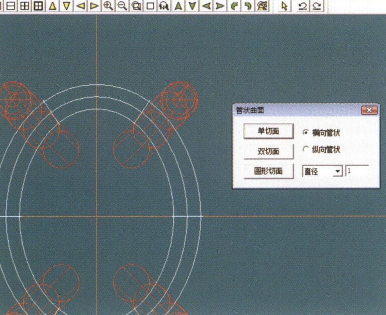
11. Select "Curved Surface" > "Tubular Surface" from the menu bar, enter the relevant values in the "Tubular Surface" dialog box and confirm
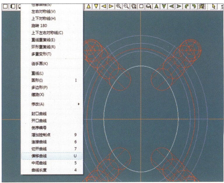
12. Select "Curve" > "Offset Curve" from the menu bar
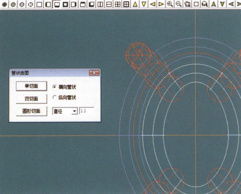
13. Select "Surface" > "Tubular Surface" from the menu bar, enter the relevant values and confirm
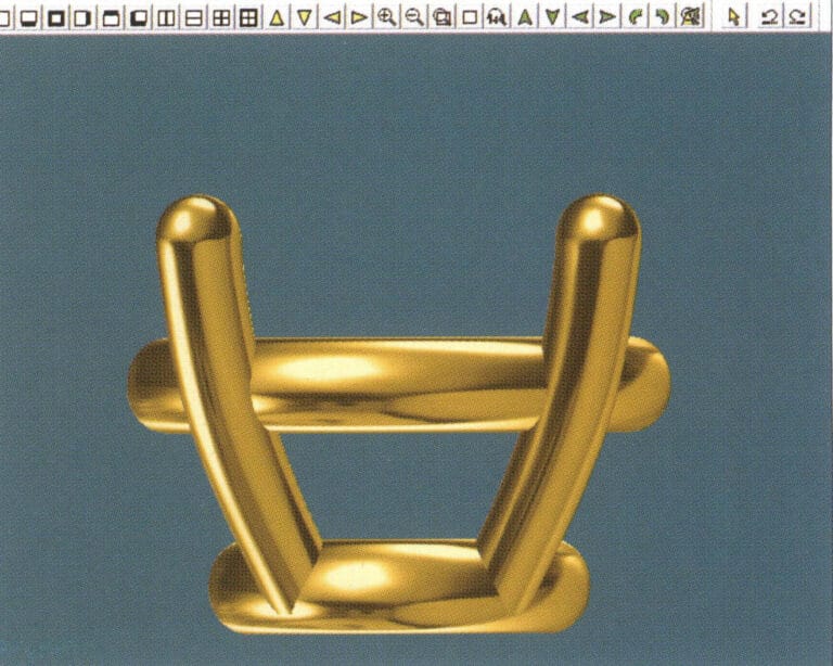
14. Select "View" > "Shadow Map" from the menu bar to examine the shadow effects and inspect the setting
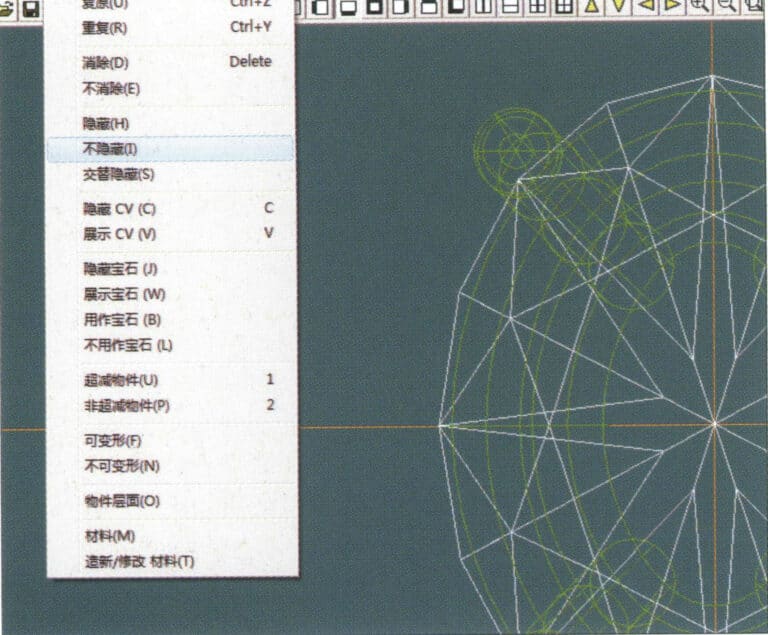
15. Select "Edit" > "Unhide" from the menu bar to display the hidden gems
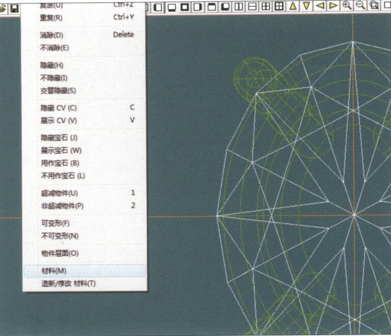
16. Select "Edit" > "Materials" from the menu bar
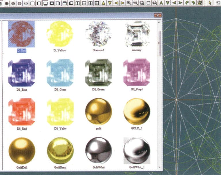
17. Entrez dans la boîte de dialogue "Matériaux", sélectionnez ruby et confirmez.
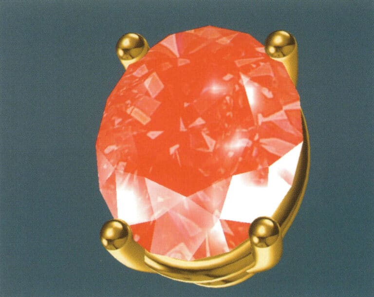
18. Select "View" > "Shadow Map" from the menu bar to examine the shadow effects
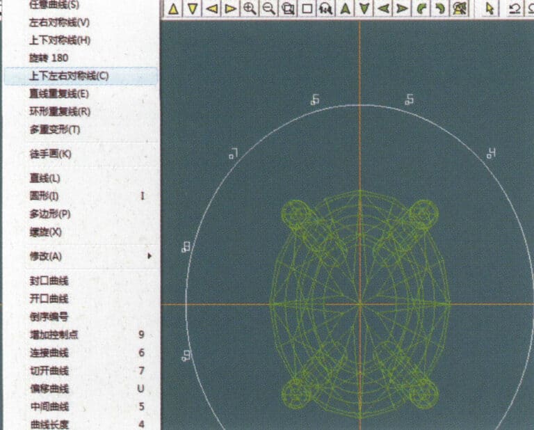
19. Select "Curve" > "Vertical and Horizontal Symmetry Line" from the menu bar as the auxiliary line for the outer circle
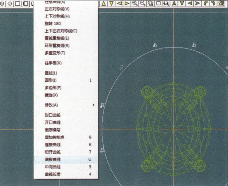
20. Select "Curve" > "Offset Curve" from the menu bar

21. Entrez dans la boîte de dialogue "Courbe de décalage", saisissez les valeurs pertinentes en tant que lignes auxiliaires pour le cercle intérieur et confirmez.
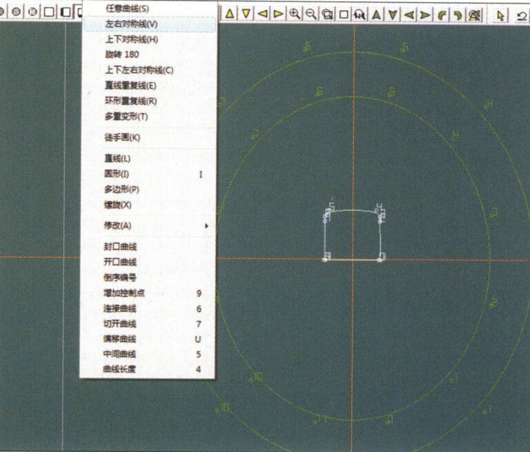
22. Select "Curve" > "Left-Right Symmetrical Line" from the menu bar as the cross-section of the coil
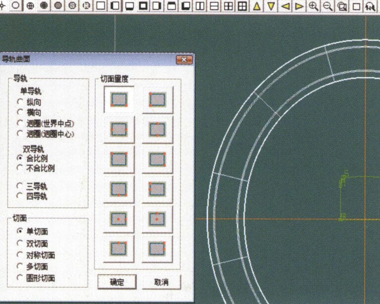
23. Select "Curved Surface" > "Rail Surface" from the menu bar to enter the "Rail Surface" dialog box, select the relevant options and confirm
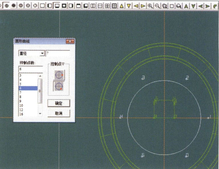
24. Select "Curve" > "Circular Curve" from the menu bar, enter the relevant values in the "Circular Curve" dialog box, and confirm; left-click on one curve as the left guide curve, click on another curve as the right guide rail, and then select the coil cross-section as the cross-section of the guide rail surface; once completed, it serves as the auxiliary line for the outer circle of the chain threading position
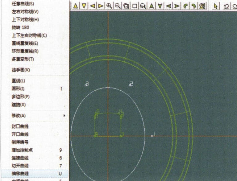
25. After completing the outer auxiliary lines for the chain position, select "Curve" > "Offset Curve" from the menu bar
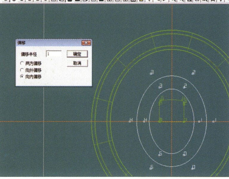
26. Entrez dans la boîte de dialogue "Courbe de décalage", saisissez les valeurs correspondantes et confirmez.
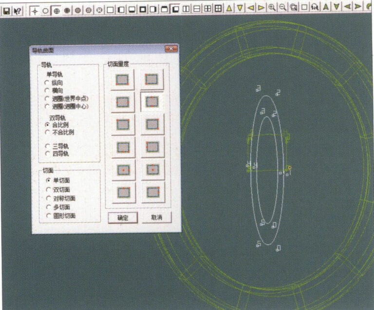
27. Select "Surface" > "Rail Surface" from the menu bar to enter the "Rail Surface" dialog box, select the relevant options and confirm, left-click on a curve to set it as the left rail curve, click on another curve to set it as the right rail, and then select the coil cross-section as the cross-section of the rail surface
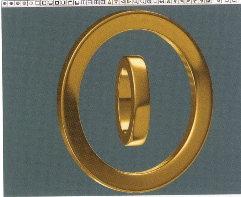
28. Select "View" > "Shadow Map" from the menu bar to inspect the shadow effects
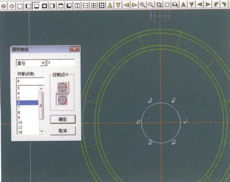
29. Select "Curve" > "Circular Curve" from the menu bar, enter the relevant values and confirm
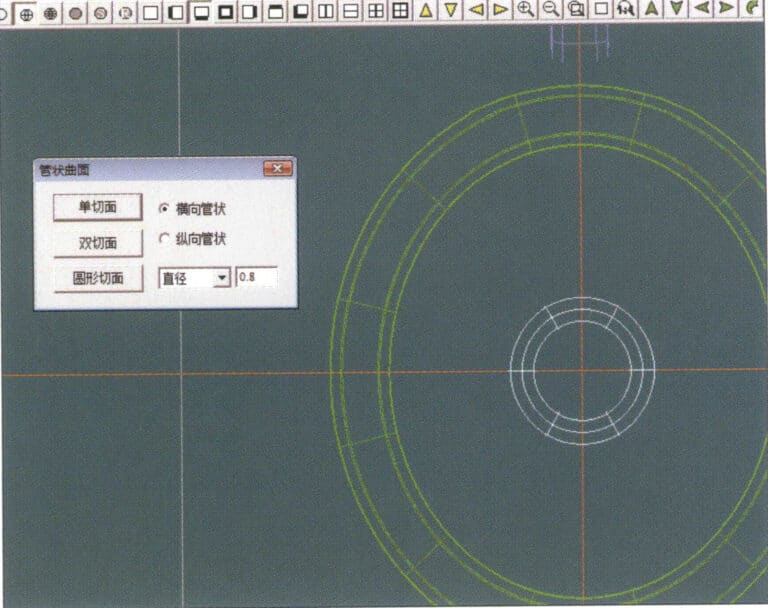
30. Select "Curved Surface" > "Tubular Surface" from the menu bar, enter the relevant values and confirm
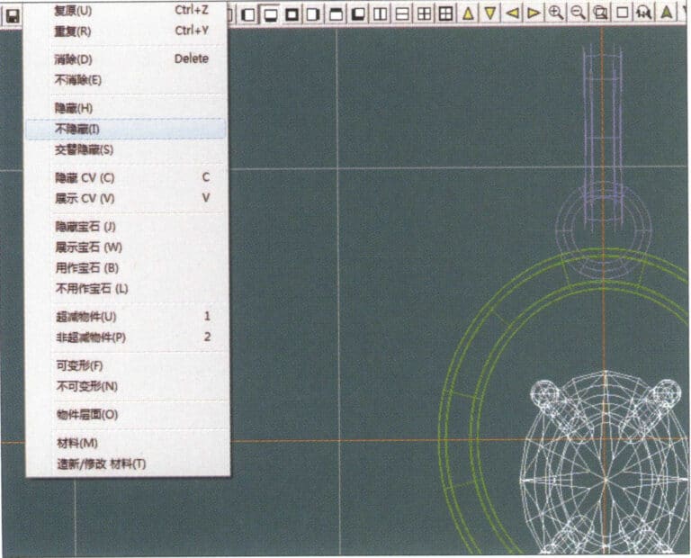
31. Select "Edit" > "Unhide" from the menu bar to display the hidden objects
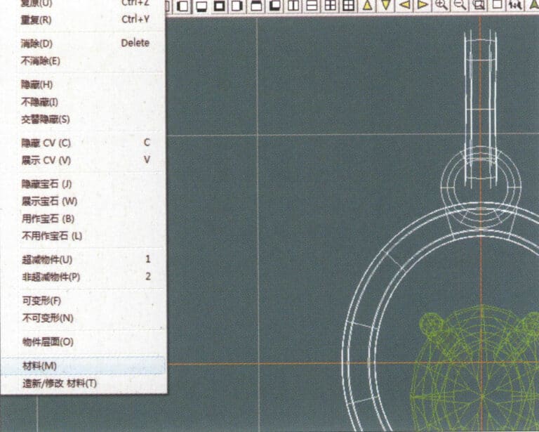
32. Select "Edit" > "Materials" from the menu bar
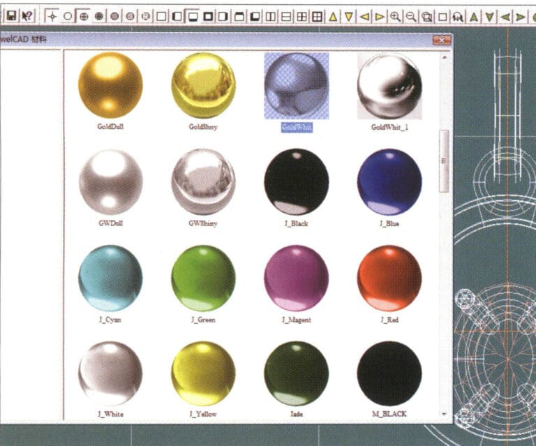
33. Entrez dans la boîte de dialogue "Matériaux", sélectionnez les matériaux appropriés et confirmez.
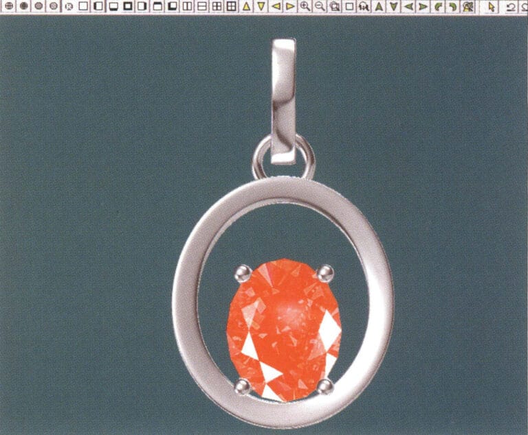
34. Select "View" > "Shadow Map" from the menu bar to inspect the shadow effects
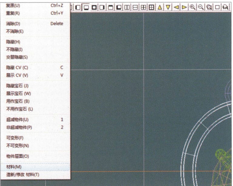
35. Select "Edit" > "Materials" from the menu bar
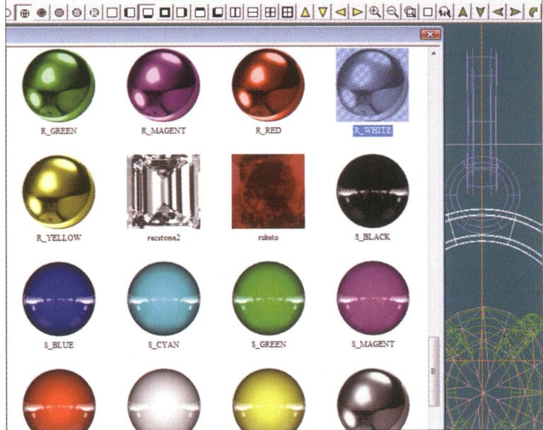
36. Entrez dans la boîte de dialogue "Matériaux", sélectionnez les matériaux de texture appropriés et confirmez.
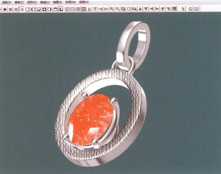
37. Select "View" > "Shadow Map" from the menu bar to inspect the shadow effects
38. Select "File" > "Save As" from the menu bar to save the file


