Cum să realizați modele 3D de bijuterii cu JewelCAD?

Learn how to make 3D jewelry models with JewelCAD. It's a powerful software for designing rings, pendants, and more. You can create different surface effects like sandblasting or brushing. It's easy to use and helps you design quickly. Perfect for jewelry stores, designers, and anyone making custom pieces.

Cum să realizați modele 3D de bijuterii cu JewelCAD?

Understanding JewelCAD, Represent Basic Material Effects and Jewelry Effects

Introducere:

What does it take to create stunning jewelry designs using JewelCAD? This guide covers everything from understanding the software to mastering material effects and crafting detailed jewelry models. Learn how to bring your ideas to life with step-by-step instructions for designing rings, pendants, and more. Discover why JewelCAD is a must-have tool for jewelry designers, studios, and brands looking to elevate their craft.
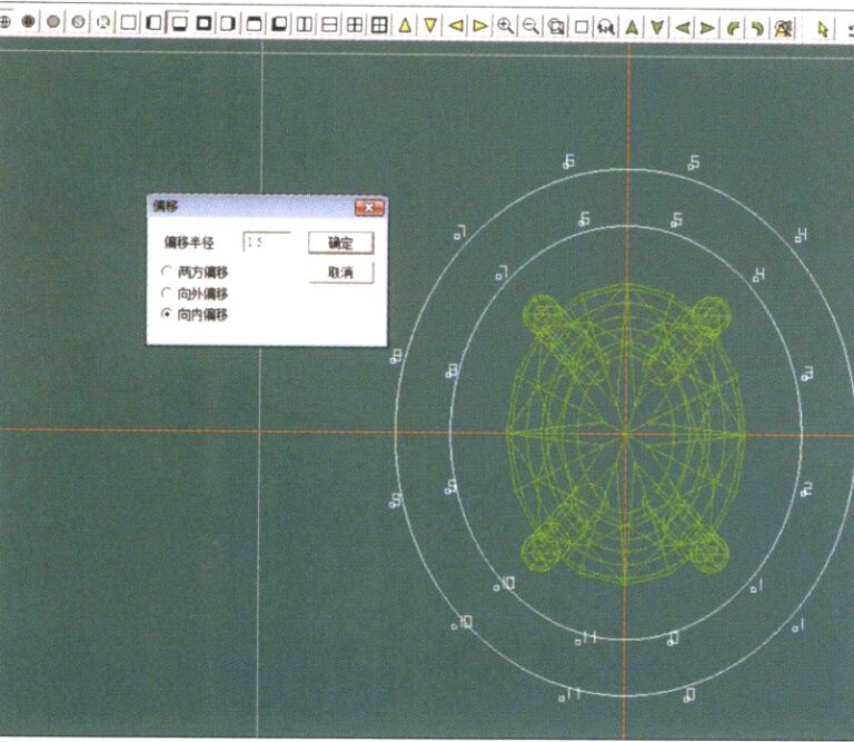
21. Intrați în caseta de dialog "Offset Curve", introduceți valorile relevante ca linii auxiliare pentru cercul interior și confirmați

Diamond-Turned Setting Ring

Tabla de conținut

Section I Understanding JewelCAD

JewelCAD is a computer-aided design system software specifically for jewelry that was successfully developed by a Hong Kong CAD/CAM company in 1990. After over a decade of development and improvement, JewelCAD has evolved from a limited-function drawing software into a powerful, stable, highly specialized, and efficient, professional jewelry design/manufacturing software widely adopted in major jewelry production areas in Europe, America, and Asia.

While the automation of production and processing in the jewelry industry has significantly improved efficiency, JewelCAD matches modern jewelry design and has been widely disseminated in current commercial applications. Its unique modeling concepts and tools allow jewelry designers to easily create three-dimensional jewelry objects, and it also integrates perfectly with CNC and RP rapid prototyping, making it a modern jewelry design software with broad development prospects. As a professional jewelry design software, JewelCAD has clear advantages over other 3D software in creating three-dimensional models of jewelry, which is reflected in the following benefits.

(1) Easy to operate, simple, and easy to learn.

(2) It has flexible drawing tools, which are very convenient for drawing curves and complex shapes.

(3) It has powerful surface modeling tools that flexibly create or modify complex designs.

(4) The rendering speed is fast; you can also compare various design effect images. The quality of the effect images is high, and the simulation is strong. It allows rotating to observe the three-dimensional effect, intuitively reflecting the final product effect.

(5) Its operation is highly efficient and suitable for changing jewelry styles.

(6) A rich professional database and various editing tools facilitate the combination and redesign of jewelry, making operations more convenient and efficient.

(7) Applying the principles of Boolean operations in software can easily unite surfaces that are in a free state.

(8) In the design, the weight of the gold, quantity, and size can be calculated directly.

(9) Can build a database to visualize design ideas and improve efficiency.

(10) The graphics drawn with JewelCAD are clearer and more consistent, reducing the likelihood of errors caused by unclear writing or poor drawing quality. It can directly output paperless images, saving time, effort, and money.

Section II Using JewelCAD to Represent Basic Material Effects

The texture of the effect image does not need to be as realistic as a photograph. However, it should still allow the viewer to perceive the differences in textures, such as jewelry and metal, especially for materials with obvious visual effects. This section provides a detailed introduction to how to use JewelCAD to design and create jewelry, achieving a specific metal surface texture effect.

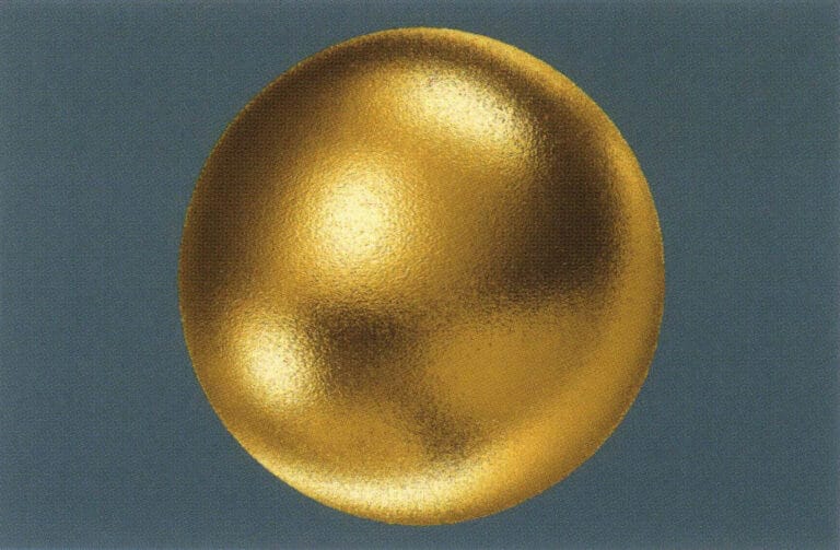
1. Sandblasting Finish Effect

Sandblasting techniques include water sandblasting, fine grit blasting, manual blasting, contrast blasting, etc. This technique is often used for plain gold jewelry and is widely applied in pure gold. The sandblasted surface created on the surface gives the jewelry a matte diffuse reflection effect.
Sandblasting Finish Effect
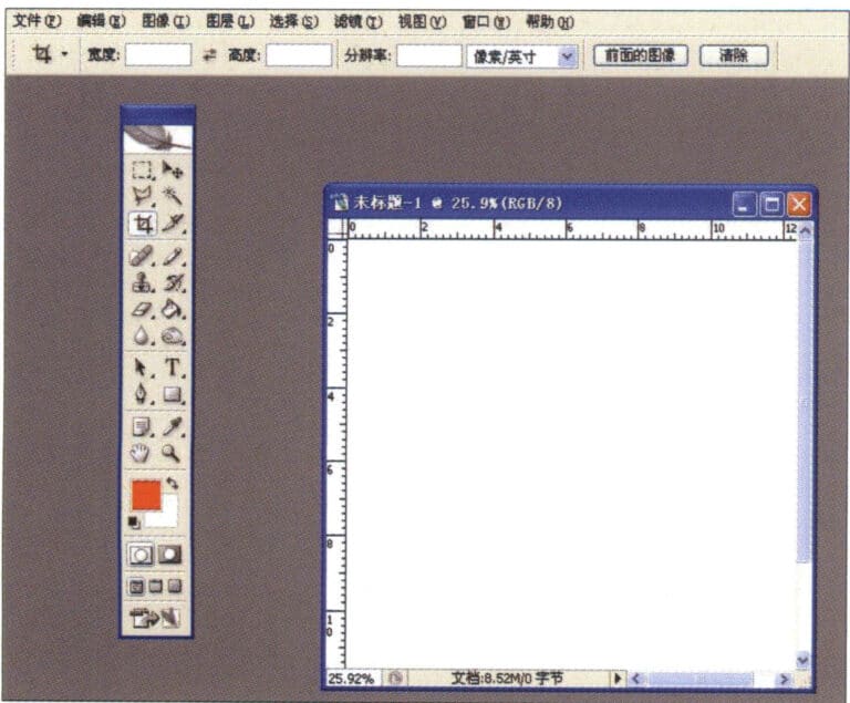
1. Create a new file in Photoshop with a resolution of 300 pixels/inch
1. Create a new file in Photoshop with a resolution of 300 pixels/inch

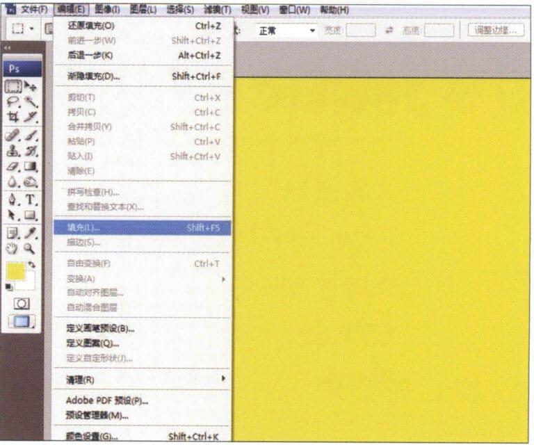
2. Select "Edit" > "Fill" from the menu bar, and set the foreground color to yellow

2. Select "Edit" > "Fill" from the menu bar, and set the foreground color to yellow

3. Select "Filter" from the menu bar > "Mottled" > "Add Mottled"
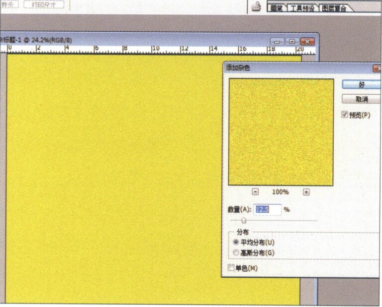
3. Select "Filter" from the menu bar > "Mottled" > "Add Mottled"

4. Enter the "Add Mottled" dialog box, input the relevant values, and confirm
4. Enter the "Add Mottled" dialog box, input the relevant values, and confirm

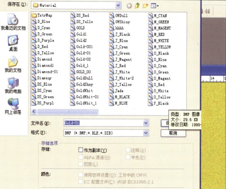
5. Store the document in the "JewelCAD" > "Material" folder, saved in "BMP" format

5. Store the document in the "JewelCAD" > "Material" folder, saved in "BMP" format

6. Create a new file in JewelCAD, select "Surface" > "Spherical Surface" from the menu bar
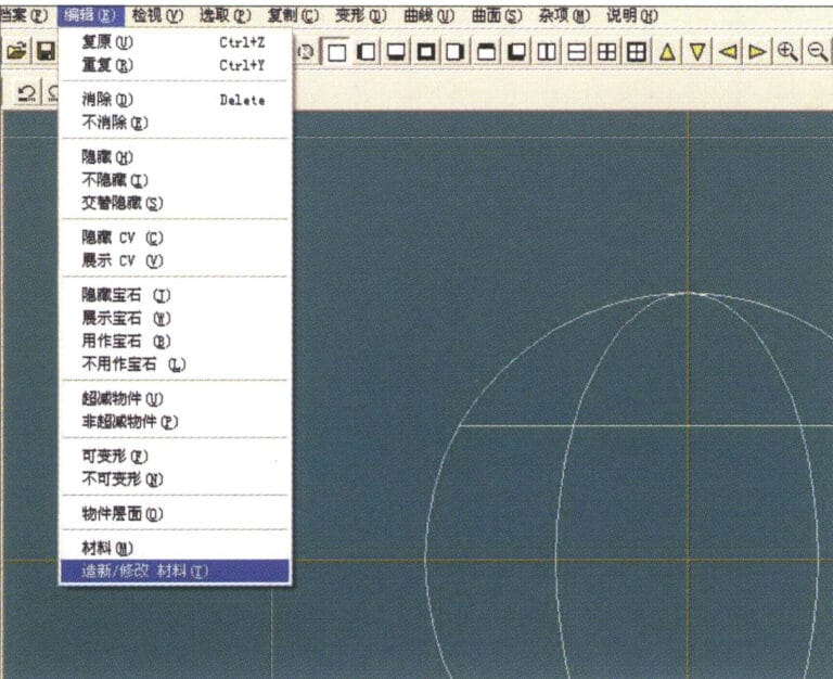
6. Create a new file in JewelCAD, select "Surface" > "Spherical Surface" from the menu bar

7. Select "Edit" > "Create/Modify Material" from the menu bar
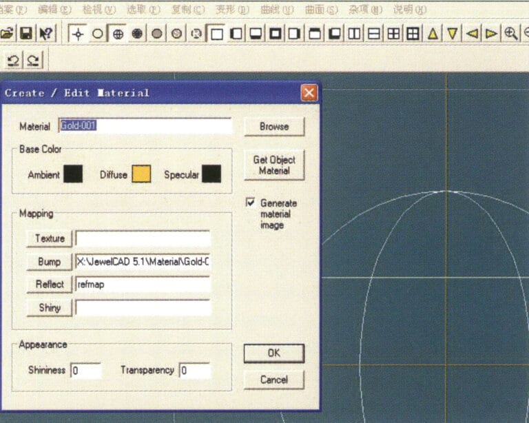
7. Select "Edit" > "Create/Modify Material" from the menu bar

8. Enter the "Create/Modify Material" dialog box, input the relevant values, and confirm
8. Enter the "Create/Modify Material" dialog box, input the relevant values, and confirm

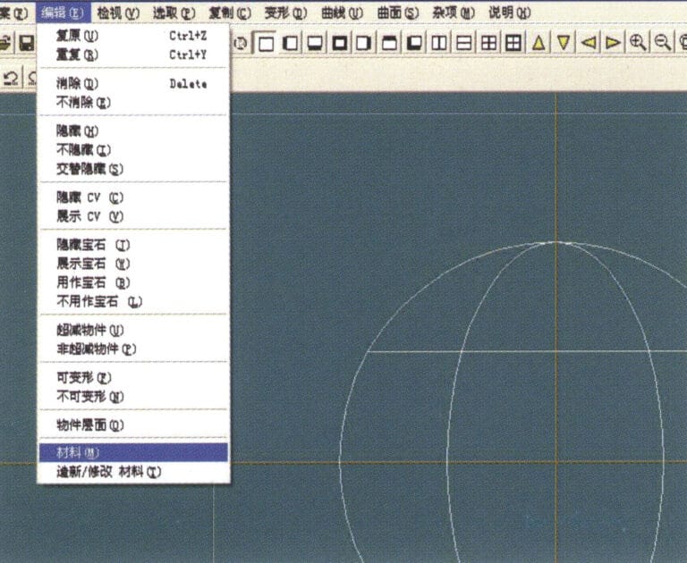
9. Select "Edit" > "Materials" from the menu bar
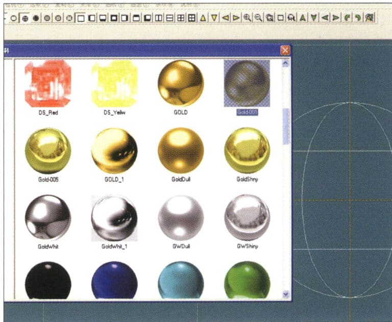
9. Select "Edit" > "Materials" from the menu bar

10. Enter the "Materials" dialog box, select the material and confirm
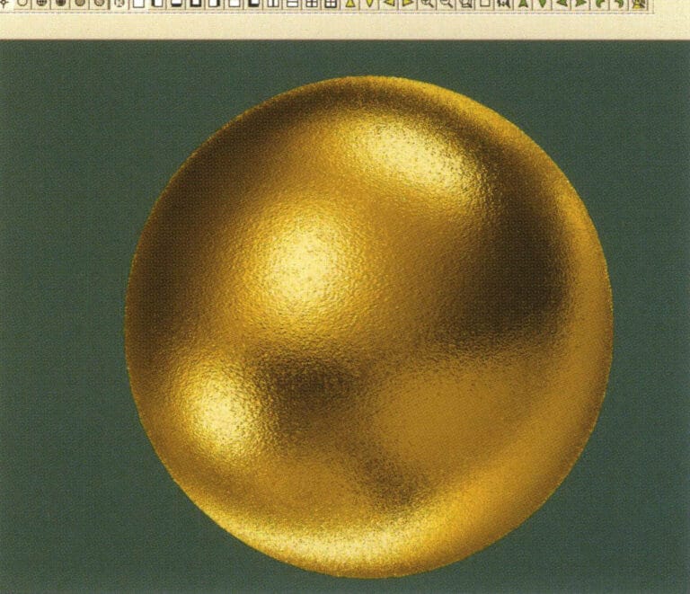
10. Enter the "Materials" dialog box, select the material and confirm

11. Select "View" > "Shadow Map" from the menu bar to inspect the shadow effects. 12. Select "File" > "Save File" from the menu bar to save the document

11. Select "View" > "Shadow Map" from the menu bar to inspect the shadow effects.

12. Select "File" > "Save File" from the menu bar to save the document

2. Brushing Effect
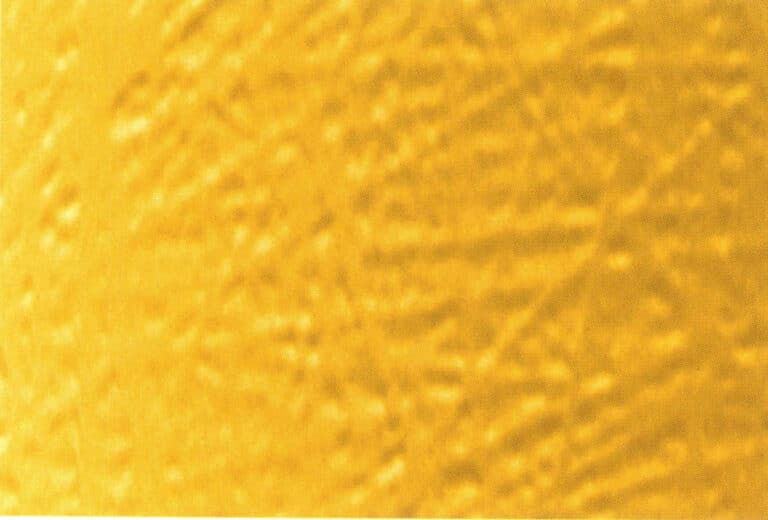
The brushed effect is often used on K gold and palladium jewelry, creating an elegant, streamlined matte finish on the surface of the pieces.
Brushing Effect
1. Scan a texture file in Photoshop with a resolution of 300 pixels/inch, and select "Filter" > "Blur" > "Motion Blur" from the menu bar to apply the blur effect
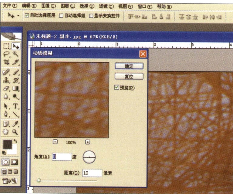
1. Scan a texture file in Photoshop with a resolution of 300 pixels/inch, and select "Filter" > "Blur" > "Motion Blur" from the menu bar to apply the blur effect

2. Enter the "Motion Blur" dialog box, input the relevant values, and confirm
2. Enter the "Motion Blur" dialog box, input the relevant values, and confirm

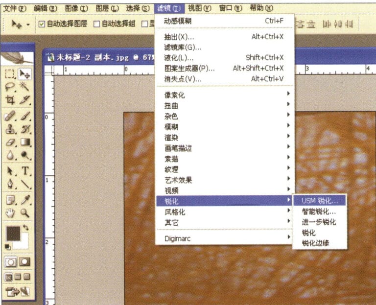
3. Select "Filter" > "Sharpen" > "USM Sharpening" from the menu bar
3. Select "Filter" > "Sharpen" > "USM Sharpening" from the menu bar

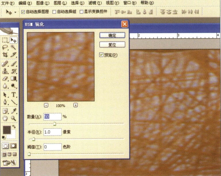
4. Enter the "USM Sharpening" dialog box, input the relevant values, and confirm
4. Enter the "USM Sharpening" dialog box, input the relevant values, and confirm

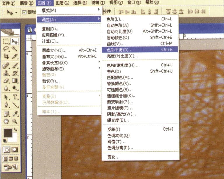
5. Select "Image" > "Adjustments" > "Color Balance" from the menu bar
5. Select "Image" > "Adjustments" > "Color Balance" from the menu bar

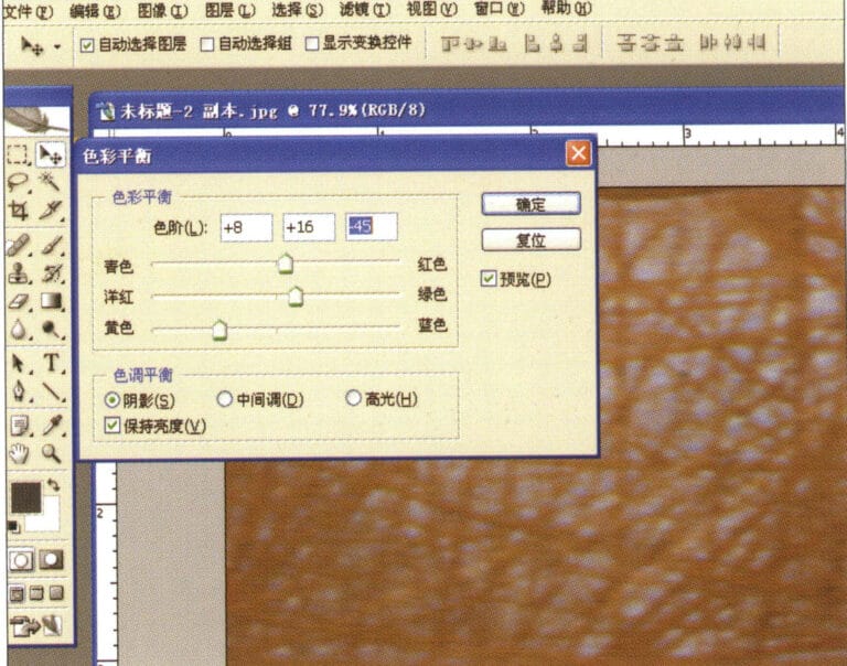
6. Enter the "Color Balance" dialog box, input the relevant values, and confirm
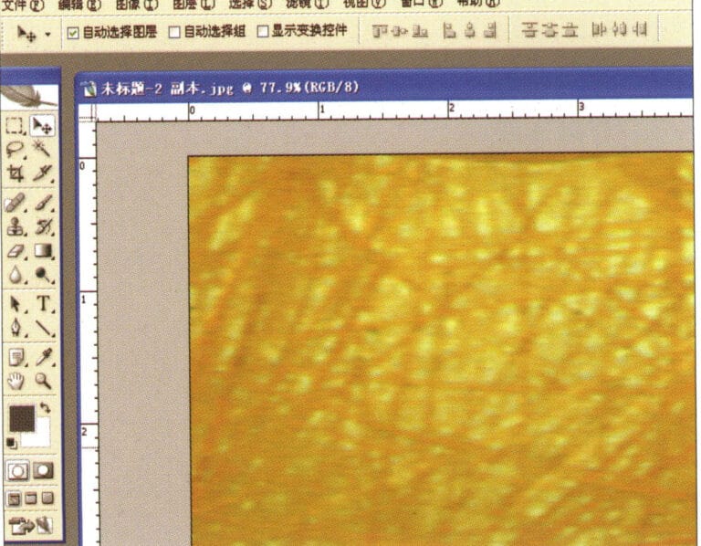
6. Enter the "Color Balance" dialog box, input the relevant values, and confirm

7. Effect diagram after displaying color balance
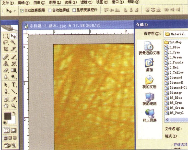
7. Effect diagram after displaying color balance

8. Store the document in the "JewelCAD" > "Material" folder, saved in "BMP" format
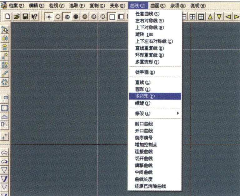
8. Store the document in the "JewelCAD" > "Material" folder, saved in "BMP" format

9. In JewelCAD, create a new file, select "Curve" > "Polygon" from the menu bar
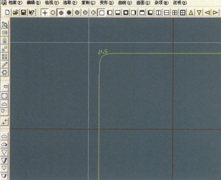
9. In JewelCAD, create a new file, select "Curve" > "Polygon" from the menu bar

10. Use "polygon" to draw a square
10. Use "polygon" to draw a square

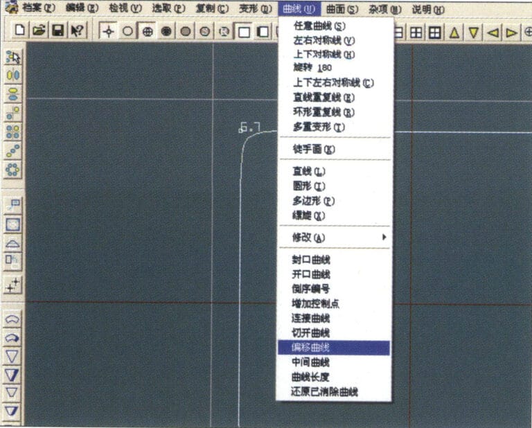
11. Select "Curve" > "Offset Curve" from the menu bar
11. Select "Curve" > "Offset Curve" from the menu bar

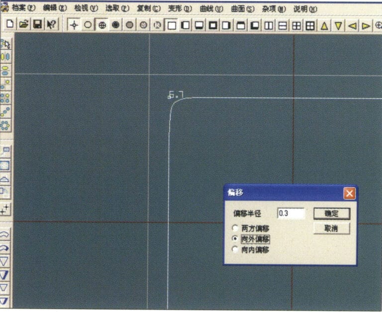
12. Enter the "Offset Curve" dialog box, input the relevant values, and confirm
12. Enter the "Offset Curve" dialog box, input the relevant values, and confirm

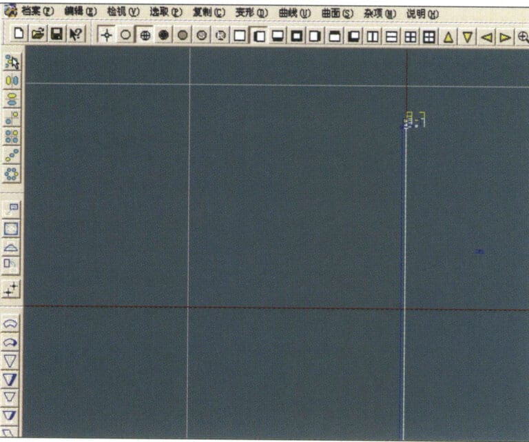
13. Effect diagram after displaying the offset curve
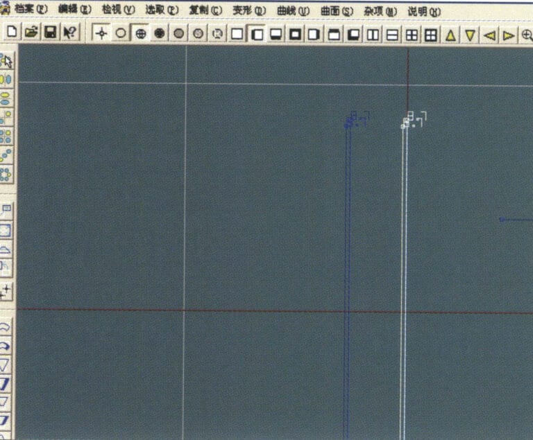
13. Effect diagram after displaying the offset curve

14. Select "Deformation" > "Move" from the menu bar to move the selected curve
14. Select "Deformation" > "Move" from the menu bar to move the selected curve

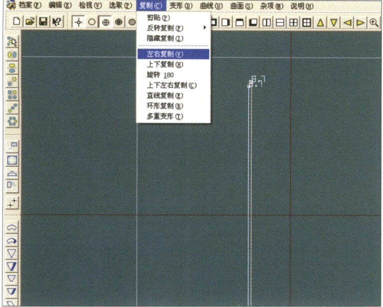
15. Select "Copy" > "Copy Left and Right" from the menu bar to copy the selected curve to the left and right
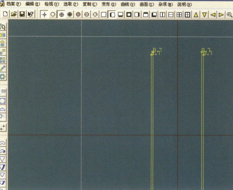
15. Select "Copy" > "Copy Left and Right" from the menu bar to copy the selected curve to the left and right

16. Display the effect images after left and right duplication
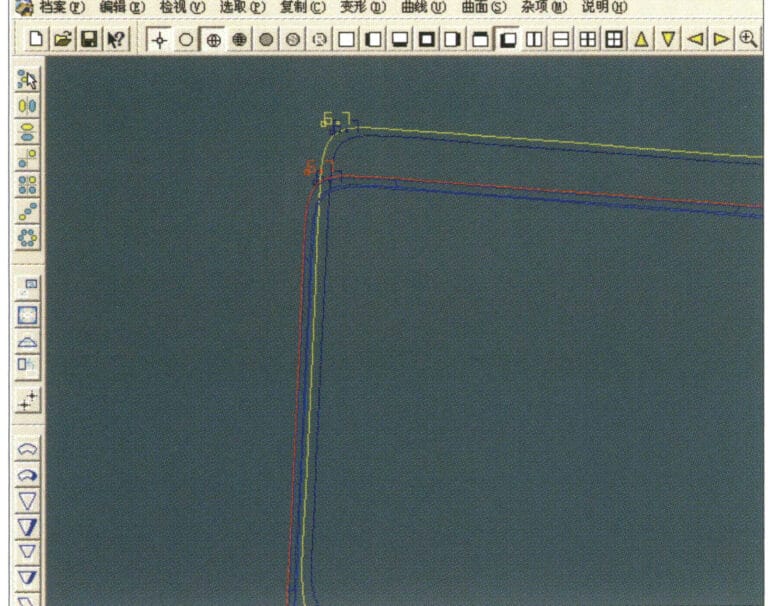
16. Display the effect images after left and right duplication

17. Select "Surface" > "Curve Surface Connection" from the menu bar, and double-click the first and second curves/surfaces in a clockwise direction with the left mouse button to create a curve surface connection
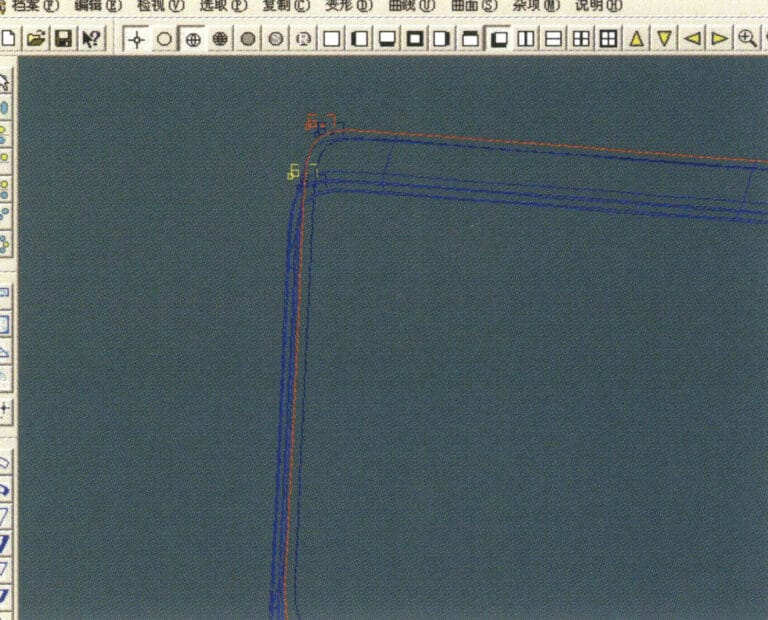
17. Select "Surface" > "Curve Surface Connection" from the menu bar, and double-click the first and second curves/surfaces in a clockwise direction with the left mouse button to create a curve surface connection

18. In a clockwise direction, double-click the third curve/surface with the left mouse button to create a line-surface connection
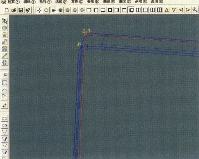
18. In a clockwise direction, double-click the third curve/surface with the left mouse button to create a line-surface connection

19. Continue clockwise; double-click the fourth curve/surface with the left mouse button to create a line-surface connection

19. Continue clockwise; double-click the fourth curve/surface with the left mouse button to create a line-surface connection

20. Select "View" > "Shadow Map" from the menu bar to inspect the shadow effects
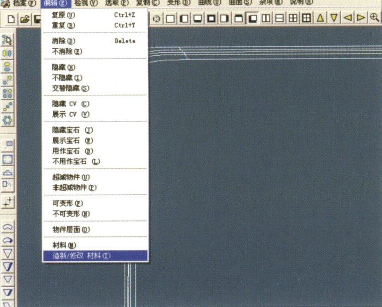
20. Select "View" > "Shadow Map" from the menu bar to inspect the shadow effects

21. Select "Edit" > "Create/Modify Material" from the menu bar
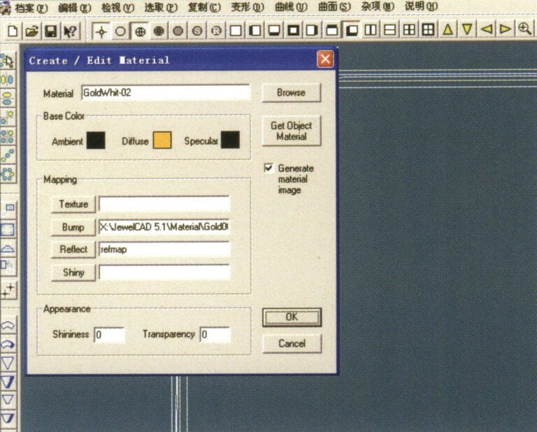
21. Select "Edit" > "Create/Modify Material" from the menu bar

22. Enter the "Create/Modify Material" dialog box, input the relevant values, and confirm
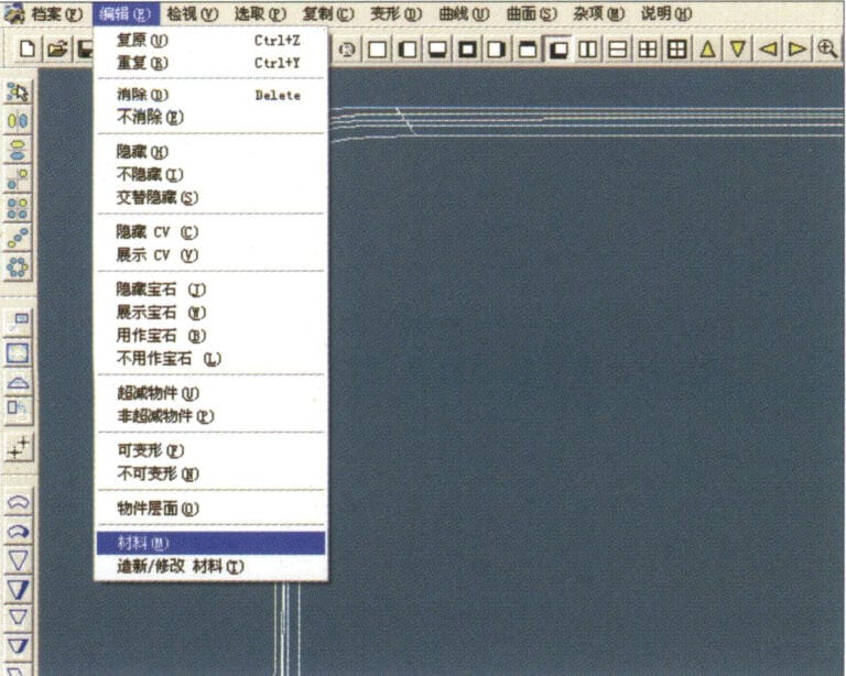
22. Enter the "Create/Modify Material" dialog box, input the relevant values, and confirm

23. Select "Edit" > "Materials" from the menu bar
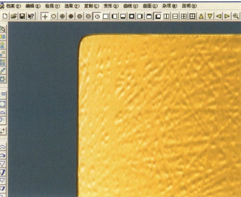
23. Select "Edit" > "Materials" from the menu bar

24. Select "View" > "Shadow Map" on the menu bar to view the light and shadow effects 25. Select "File" > "Save File" on the menu bar to save the file

24. Select "View" > "Shadow Map" on the menu bar to view the light and shadow effects 25. Select "File" > "Save File" on the menu bar to save the file

3. Bark Texture Finish
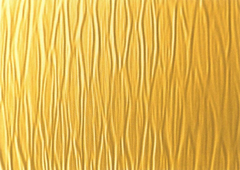
Bark effect is mostly used in silver jewelry, the surface to create bark texture to make the surface of the jewelry to form a rough texture effect.
Bark Texture Finish
1. Scan a texture file into Photoshop with a resolution of 300 pixels/inch
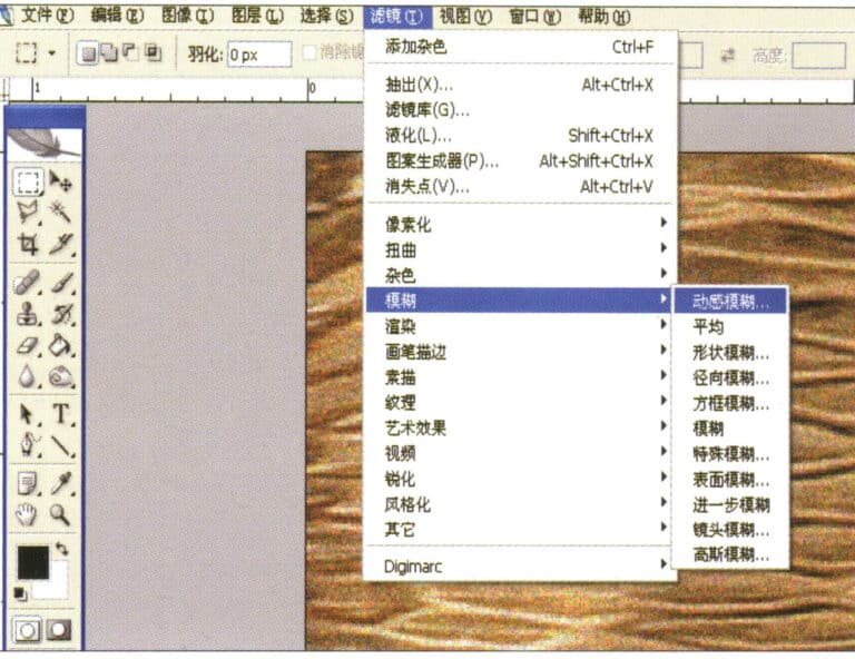
1. Scan a texture file into Photoshop with a resolution of 300 pixels/inch

2. Select "Filter" > "Blur" > "Motion Blur" from the menu bar
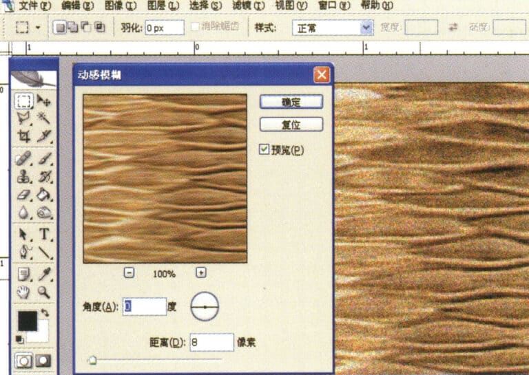
2. Select "Filter" > "Blur" > "Motion Blur" from the menu bar

3. Enter the "Motion Blur" dialog box, input the relevant values, and confirm
3. Enter the "Motion Blur" dialog box, input the relevant values, and confirm

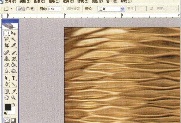
4. Display the effect image after motion blur
4. Display the effect image after motion blur

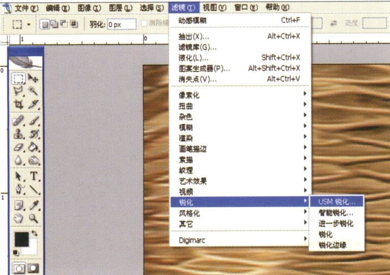
5. Select "Filter" > "Sharpen" > "USM Sharpening" from the menu bar
5. Select "Filter" > "Sharpen" > "USM Sharpening" from the menu bar

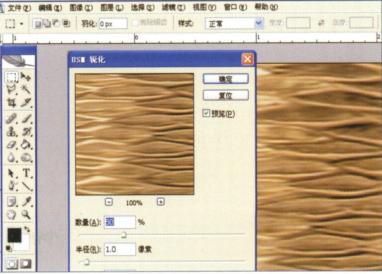
6. Enter the "USM Sharpening" dialog box, input the relevant values, and confirm
6. Enter the "USM Sharpening" dialog box, input the relevant values, and confirm

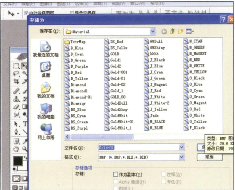
7. Store the document in the "JewelCAD" > "Material" folder and save it in "BMP" format
7. Store the document in the "JewelCAD" > "Material" folder and save it in "BMP" format

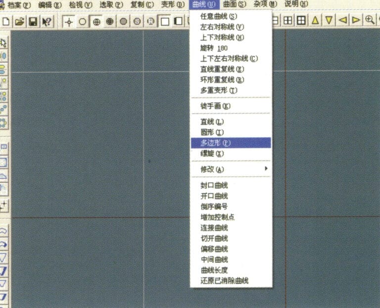
8. In JewelCAD, create a new file, select "Curve" > "Polygon" from the menu bar
8. In JewelCAD, create a new file, select "Curve" > "Polygon" from the menu bar

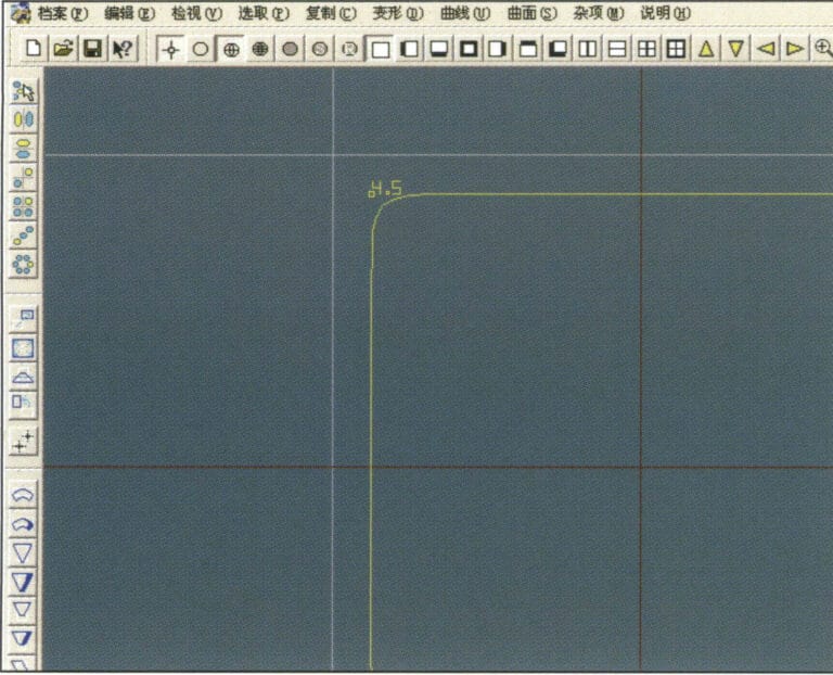
9. Use "polygon" to draw a square
9. Use "polygon" to draw a square

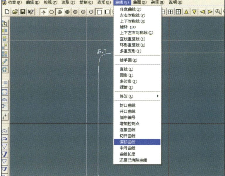
10. Select "Curve" > "Offset Curve" from the menu bar
10. Select "Curve" > "Offset Curve" from the menu bar

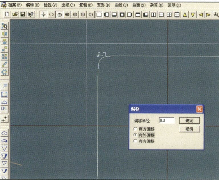
11. Enter the "Offset Curve" dialog box, input the relevant values, and confirm
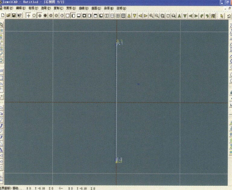
11. Enter the "Offset Curve" dialog box, input the relevant values, and confirm

12. Effect diagram after displaying the offset curve
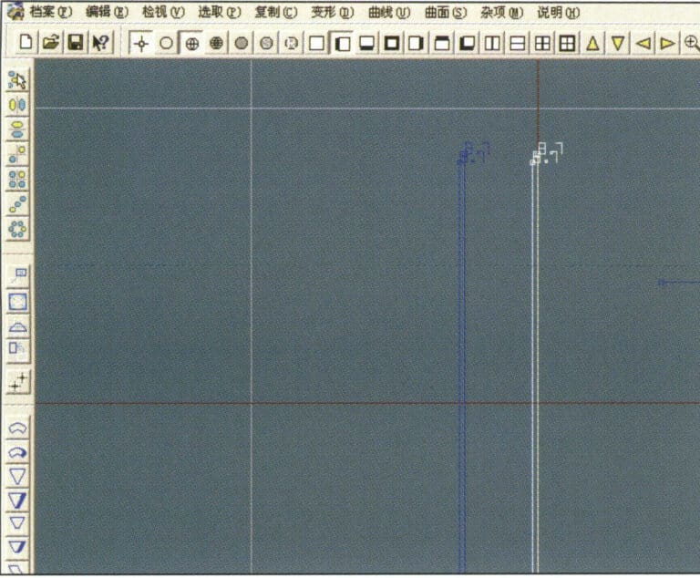
12. Effect diagram after displaying the offset curve

13. Select "Deformation" > "Move" from the menu bar to move the selected curve
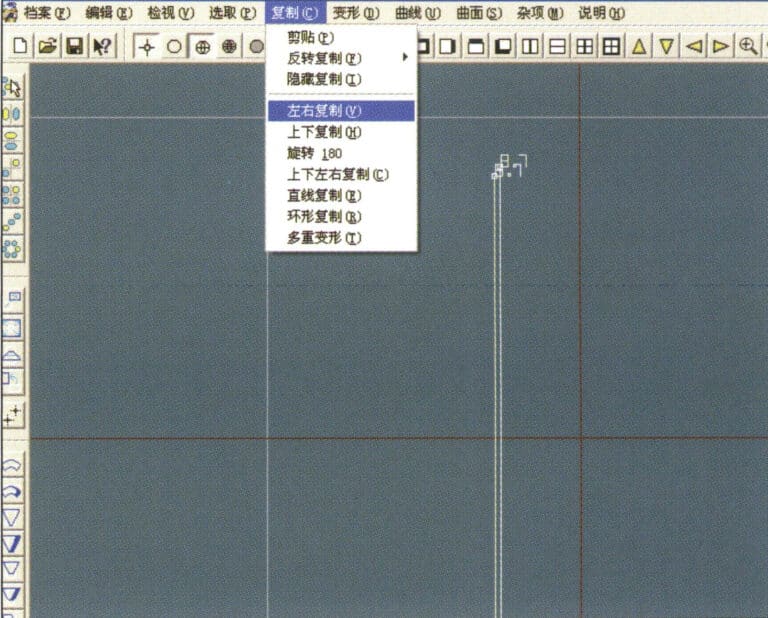
13. Select "Deformation" > "Move" from the menu bar to move the selected curve

14. Select "Copy" > "Copy Left and Right" from the menu bar to copy the selected curve to the left and right
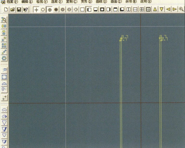
14. Select "Copy" > "Copy Left and Right" from the menu bar to copy the selected curve to the left and right

15. Display the effect images after copying left and right
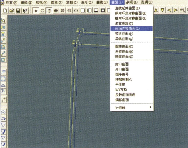
15. Display the effect images after copying left and right

16. Select "Surface" > "Line-Surface Connection Surface" from the menu bar, and select the curve/surface to create a line-surface connection surface
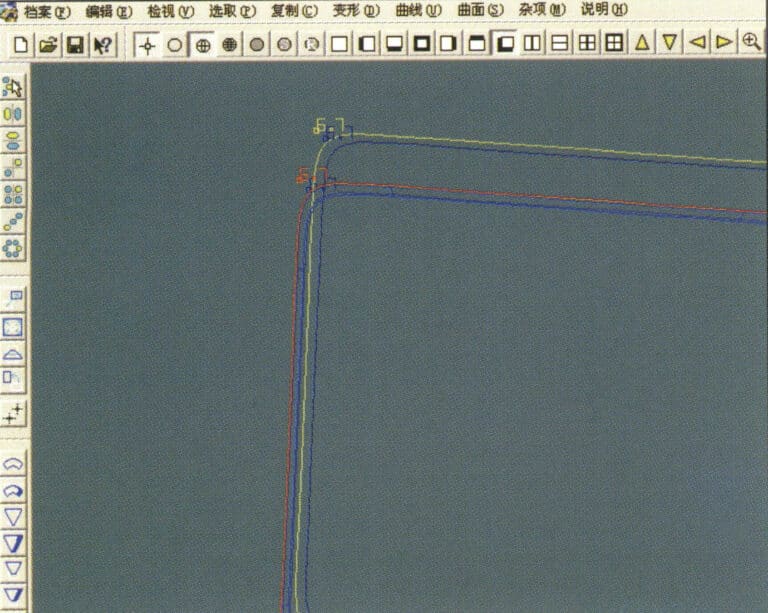
16. Select "Surface" > "Line-Surface Connection Surface" from the menu bar, and select the curve/surface to create a line-surface connection surface

17. Select the menu bar "Surface" > "Curve Surface Connection," and double-click the first and second curves/surfaces with the left mouse button in a clockwise direction to create a curve surface connection
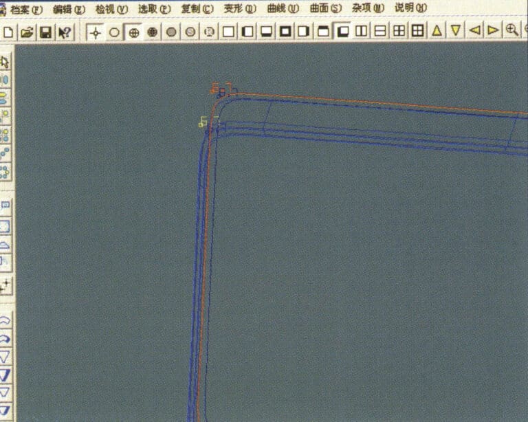
17. Select the menu bar "Surface" > "Curve Surface Connection," and double-click the first and second curves/surfaces with the left mouse button in a clockwise direction to create a curve surface connection

18. In a clockwise direction, double-click the third curve/surface with the left mouse button to create a line-surface connection
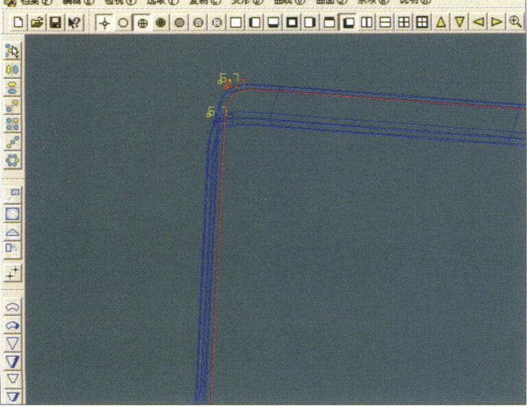
18. In a clockwise direction, double-click the third curve/surface with the left mouse button to create a line-surface connection

19. Continue clockwise; double-click the fourth curve/surface with the left mouse button to create a line-surface connection
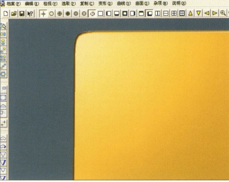
19. Continue clockwise; double-click the fourth curve/surface with the left mouse button to create a line-surface connection

20. Select "View" > "Shadow Map" from the menu bar to inspect the shadow effects
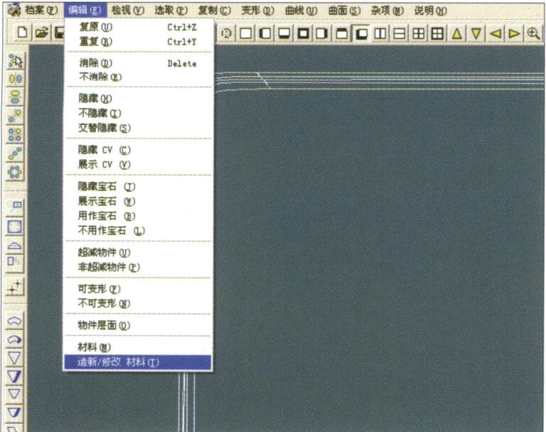
20. Select "View" > "Shadow Map" from the menu bar to inspect the shadow effects

21. Select "Edit" > "Create/Modify Material" from the menu bar
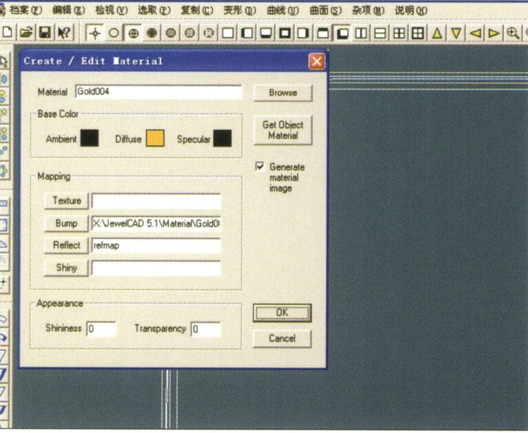
21. Select "Edit" > "Create/Modify Material" from the menu bar

22. Enter the "Create/Modify Material" dialog box, input the relevant values, and confirm
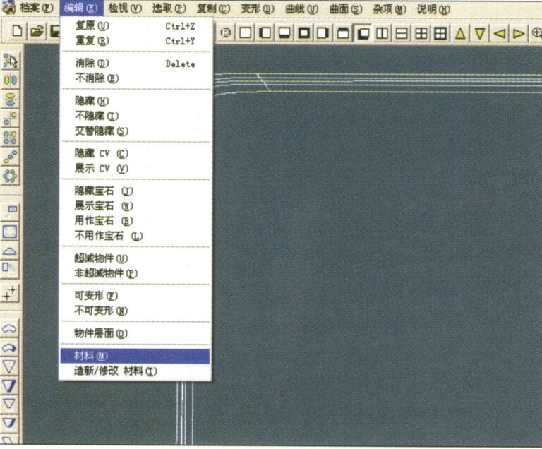
22. Enter the "Create/Modify Material" dialog box, input the relevant values, and confirm

23. Select “Edit” > “Material” in the menu bar
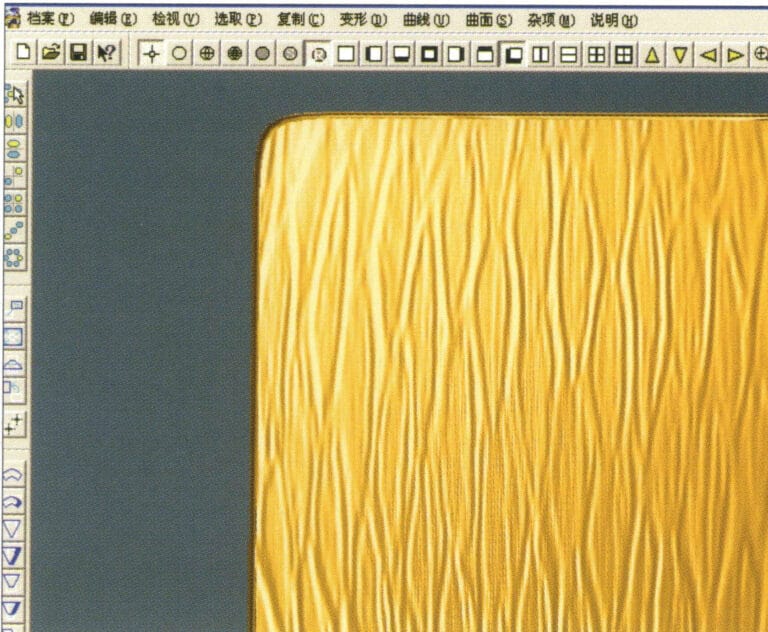
23. Select “Edit” > “Material” in the menu bar

24. Select "View" > "Shadow Map" from the menu bar to examine the shadow effects 25. Select "File" > "Save As" from the menu bar to save the file

24. Select "View" > "Shadow Map" from the menu bar to examine the shadow effects

25. Select "File" > "Save As" from the menu bar to save the file

4. Engine-Turned Finish
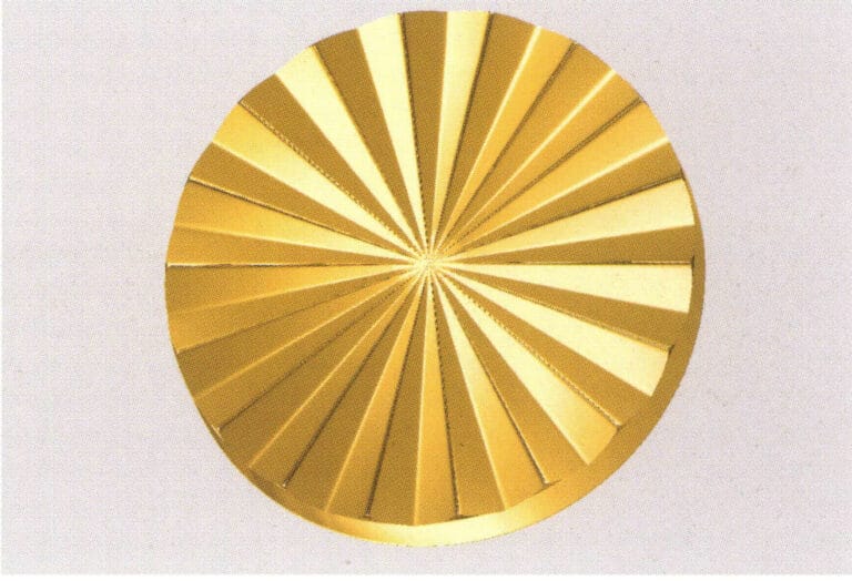
The forms of engine-turned finish are diverse, including rice-shaped and cross-shaped designs. This craft effect is mostly used in plain gold jewelry, where the engine-turned surface created makes the jewelry’s surface exhibit a dazzling brilliance under the refraction of light.
Engine-Turned Finish
1. Create a new file in JewelCAD, select "Curve" > "Circular Curve" from the menu bar, enter the relevant values in the "Circular Curve" dialog box, and confirm
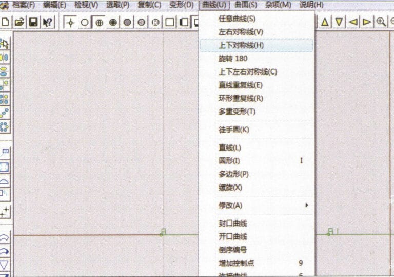
1. Create a new file in JewelCAD, select "Curve" > "Circular Curve" from the menu bar, enter the relevant values in the "Circular Curve" dialog box, and confirm

2. Select "Curve" > "Left-Right Symmetry Line" from the menu bar to draw a section
2. Select "Curve" > "Left-Right Symmetry Line" from the menu bar to draw a section

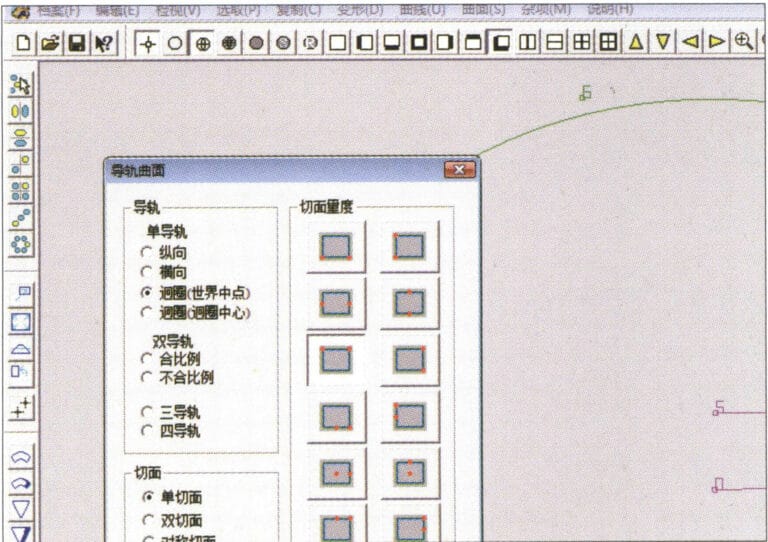
3. Select "Surface" > "Rail Surface" from the menu bar, enter "Rail Surface," select the relevant options and confirm; left-click on a curve as the section of the rail surface; left-click on another curve as the "Rail" > "Finish."

3. Select "Surface" > "Rail Surface" from the menu bar, enter "Rail Surface," select the relevant options and confirm; left-click on a curve as the section of the rail surface; left-click on another curve as the "Rail" > "Finish."

4. Select “View” > “Shadow Map” on the menu bar to view the light and shadow effects
4. Select “View” > “Shadow Map” on the menu bar to view the light and shadow effects

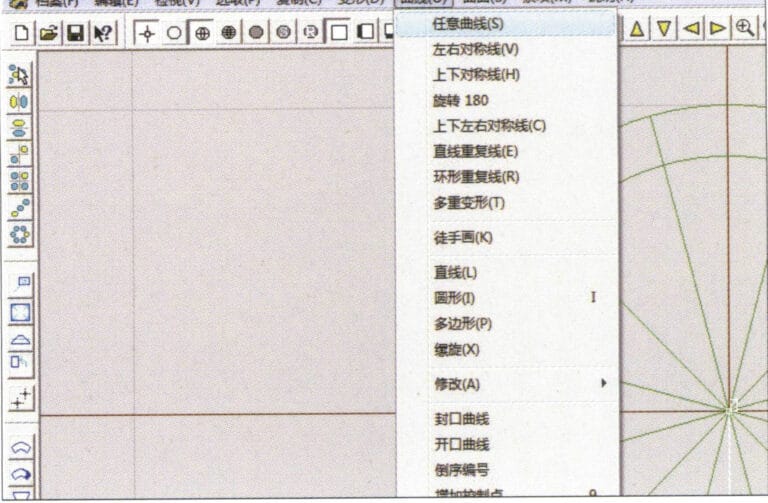
5. Select "Curve" > "Freefrom Curve" from the menu bar
5. Select "Curve" > "Freefrom Curve" from the menu bar

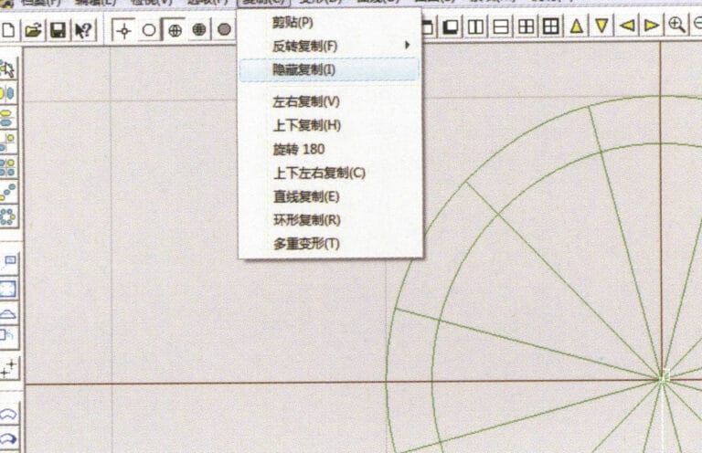
6. Select "Copy" > "Hide Copy" from the menu bar
6. Select "Copy" > "Hide Copy" from the menu bar

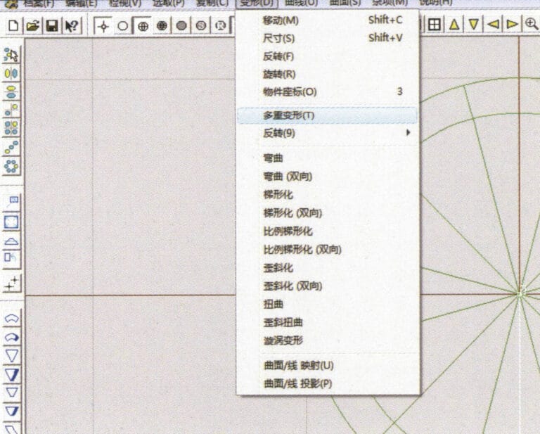
7. Select "Deformation" > "Multiple Deformation" from the menu bar
7. Select "Deformation" > "Multiple Deformation" from the menu bar

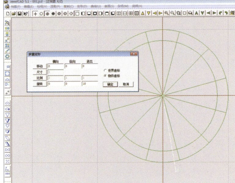
8. Enter the "Multiple Deformation" dialog box and input the relevant values
8. Enter the "Multiple Deformation" dialog box and input the relevant values

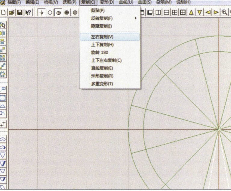
9. Select “Copy” > “Left/Right Copy” on the menu bar
9. Select “Copy” > “Left/Right Copy” on the menu bar

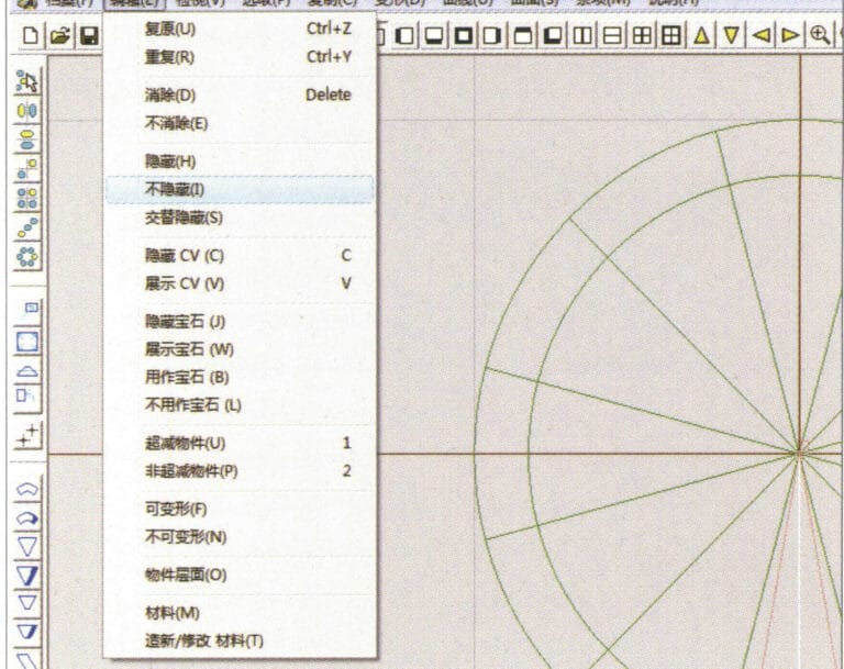
10. Select "Edit" > "Unhide" from the menu bar to display the hidden curves
10. Select "Edit" > "Unhide" from the menu bar to display the hidden curves

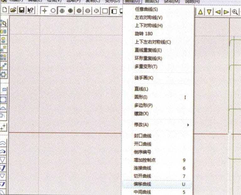
11. Select "Curve" > "Offset Curve" from the menu bar
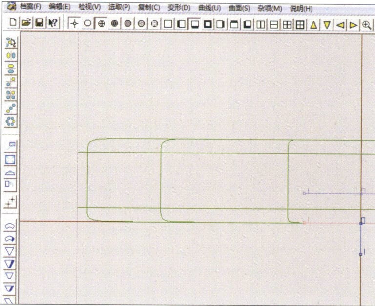
11. Select "Curve" > "Offset Curve" from the menu bar

12. Select "Deformation" > "Move" from the menu bar to move the selected curve
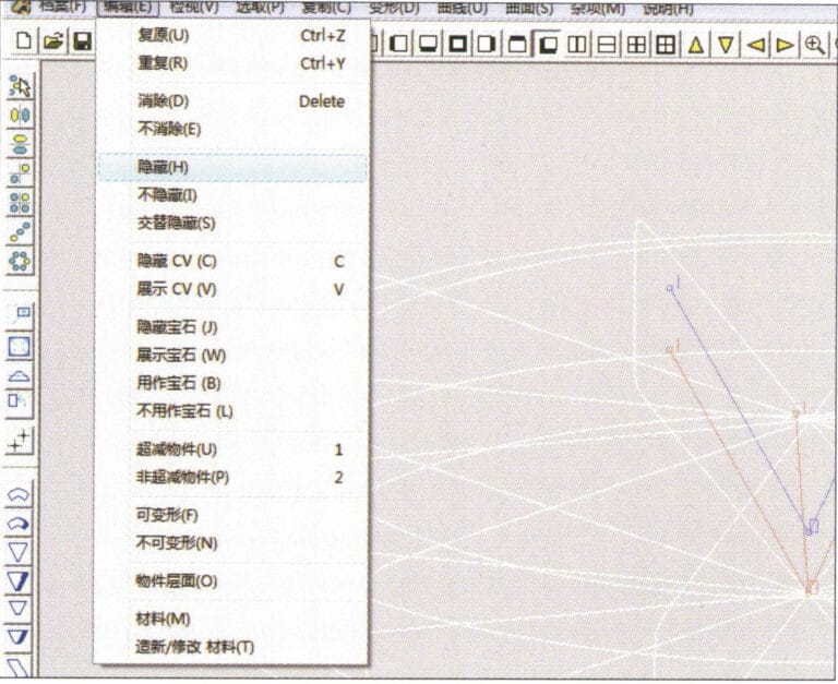
12. Select "Deformation" > "Move" from the menu bar to move the selected curve

13. Select "Edit" > "Hide" from the menu bar to hide the circular surface
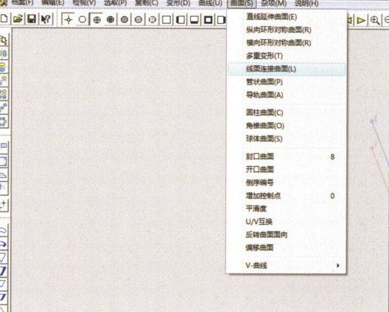
13. Select "Edit" > "Hide" from the menu bar to hide the circular surface

14. Select "Surface" > "Line Surface Connection Surface" from the menu bar

14. Select "Surface" > "Line Surface Connection Surface" from the menu bar

15. Select curves/surfaces in a clockwise direction to create line-surface connections, then select from the menu bar
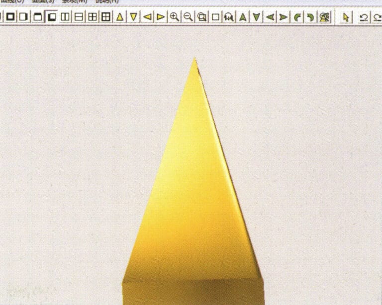
15. Select curves/surfaces in a clockwise direction to create line-surface connections, then select from the menu bar

16. Select "View" > "Shadow Map" from the menu bar to inspect the shadow effects
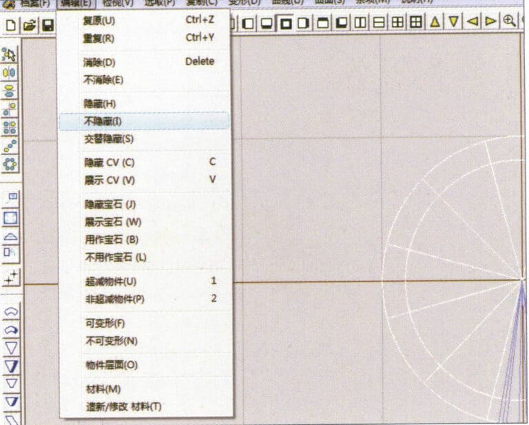
16. Select "View" > "Shadow Map" from the menu bar to inspect the shadow effects

17. Select "Edit" > "Unhide" from the menu bar to display the hidden circular surfaces
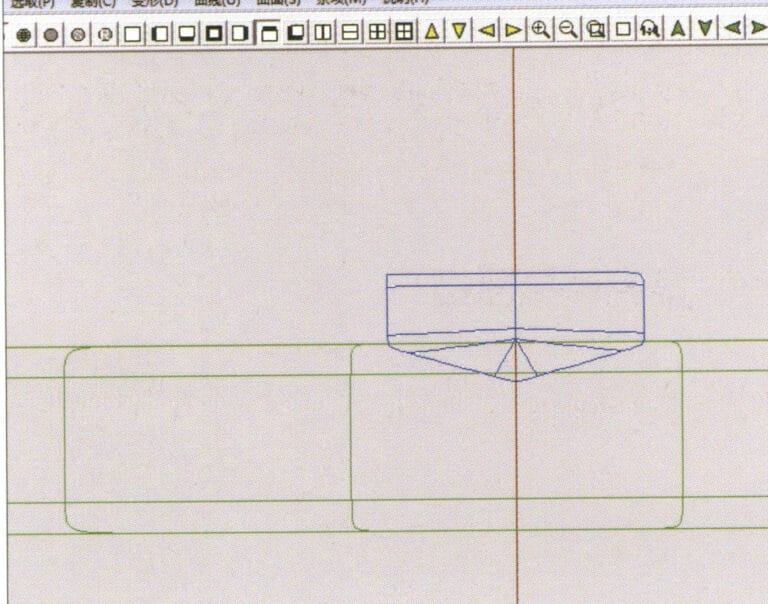
17. Select "Edit" > "Unhide" from the menu bar to display the hidden circular surfaces

18. Select "Deformation" > "Move" from the menu bar to move the selected surface
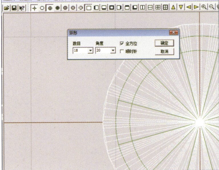
18. Select "Deformation" > "Move" from the menu bar to move the selected surface

19. Select "Copy" > "Circular Copy" from the menu bar, enter the relevant values and confirm

19. Select "Copy" > "Circular Copy" from the menu bar, enter the relevant values and confirm

20. Select “Miscellaneous” > “Boolean” > “Integrate” on the menu bar to integrate the selected surfaces.
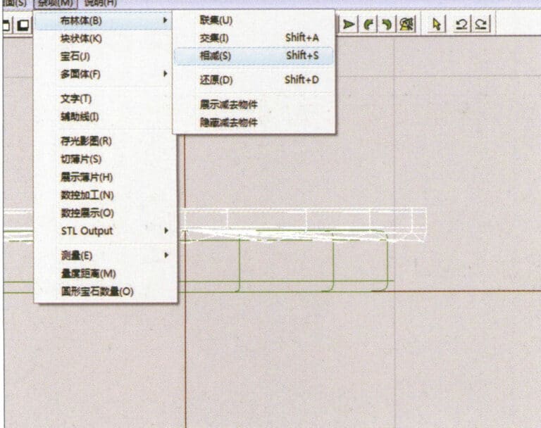
20. Select “Miscellaneous” > “Boolean” > “Integrate” on the menu bar to integrate the selected surfaces.

21. Select "Miscellaneous" > "Boolean" > "Subtract" from the menu bar to subtract the selected surface from the already united surface
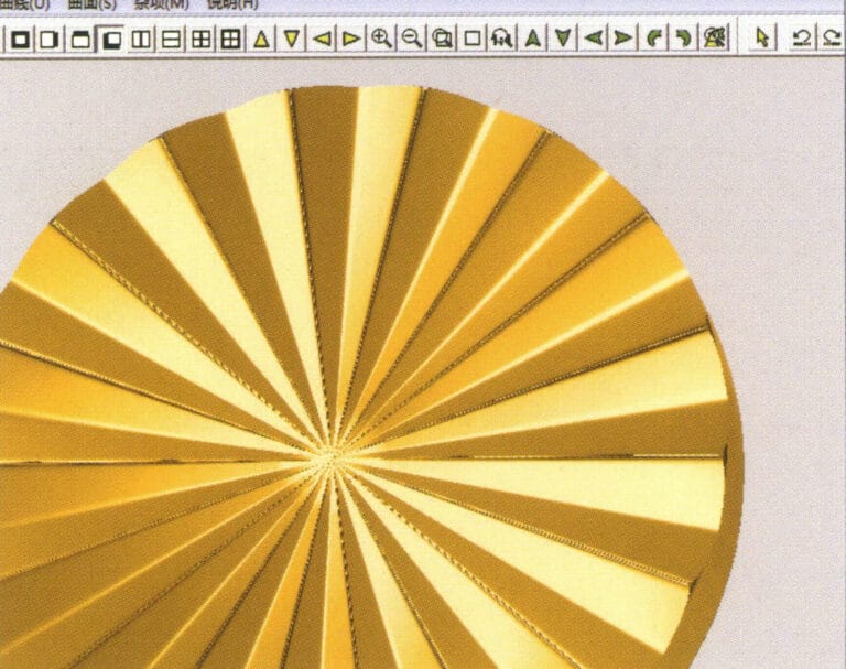
21. Select "Miscellaneous" > "Boolean" > "Subtract" from the menu bar to subtract the selected surface from the already united surface

22. Select "View" > "Shadow Map" from the menu bar to inspect the shadow effects. 23. Select "File" > "Save File" from the menu bar to save the document

22. Select "View" > "Shadow Map" from the menu bar to inspect the shadow effects.

23. Select "File" > "Save File" from the menu bar to save the document

Section III Using JewelCAD to Create Jewelry Effects

1. Diamond-Turned Setting Ring
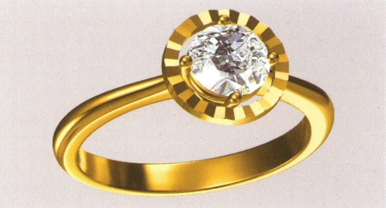
21

Etapele de producție sunt următoarele:
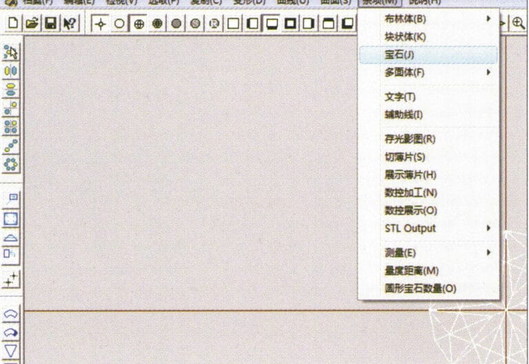
1. Create a new file in JewelCAD, select "Miscellaneous" > "Gem" from the menu bar

1. Create a new file in JewelCAD, select "Miscellaneous" > "Gem" from the menu bar

2. Select "Deformation" > "Multiple Deformation" from the menu bar
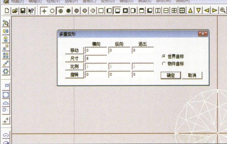
2. Select "Deformation" > "Multiple Deformation" from the menu bar

3. Enter the "Multiple Deformation" dialog box, input the relevant values, and confirm
3. Enter the "Multiple Deformation" dialog box, input the relevant values, and confirm

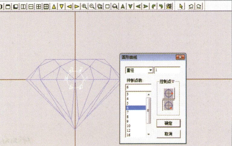
4. Select “Curve” > “Circular Curve” in the menu bar to enter the “Circular Curve” dialog box, enter the relevant values and confirm
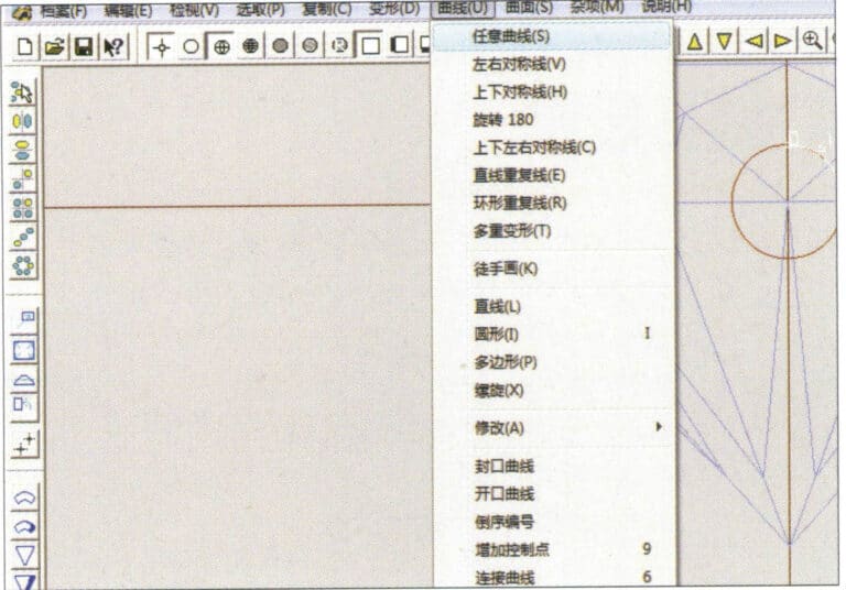
4. Select “Curve” > “Circular Curve” in the menu bar to enter the “Circular Curve” dialog box, enter the relevant values and confirm

5. Select "Curve" > "Freeform Curve" from the menu bar to draw a claw-shaped guideline
5. Select "Curve" > "Freeform Curve" from the menu bar to draw a claw-shaped guideline

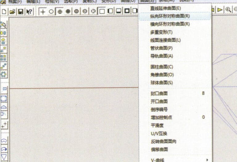
6. Select "Surface" > "Longitudinal Annular Symmetrical Surface" from the menu bar, and draw a claw shape
6. Select "Surface" > "Longitudinal Annular Symmetrical Surface" from the menu bar, and draw a claw shape

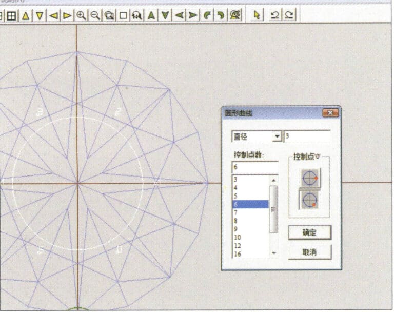
7. Select "Curve" > "Circular Curve" from the menu bar, enter the relevant values in the "Circular Curve" dialog box and confirm
7. Select "Curve" > "Circular Curve" from the menu bar, enter the relevant values in the "Circular Curve" dialog box and confirm

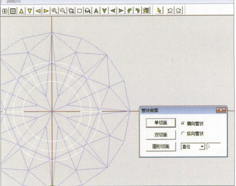
8. Select "Surface" > "Tubular Surface" from the menu bar, enter the relevant values and confirm
8. Select "Surface" > "Tubular Surface" from the menu bar, enter the relevant values and confirm

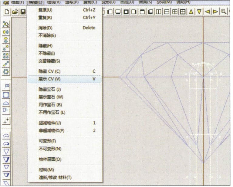
9. Select “Edit” > “Show CV” in the menu bar
9. Select “Edit” > “Show CV” in the menu bar

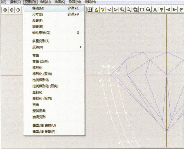
10. Select “Deformation” > “Move” in the menu bar to move the CV
10. Select “Deformation” > “Move” in the menu bar to move the CV

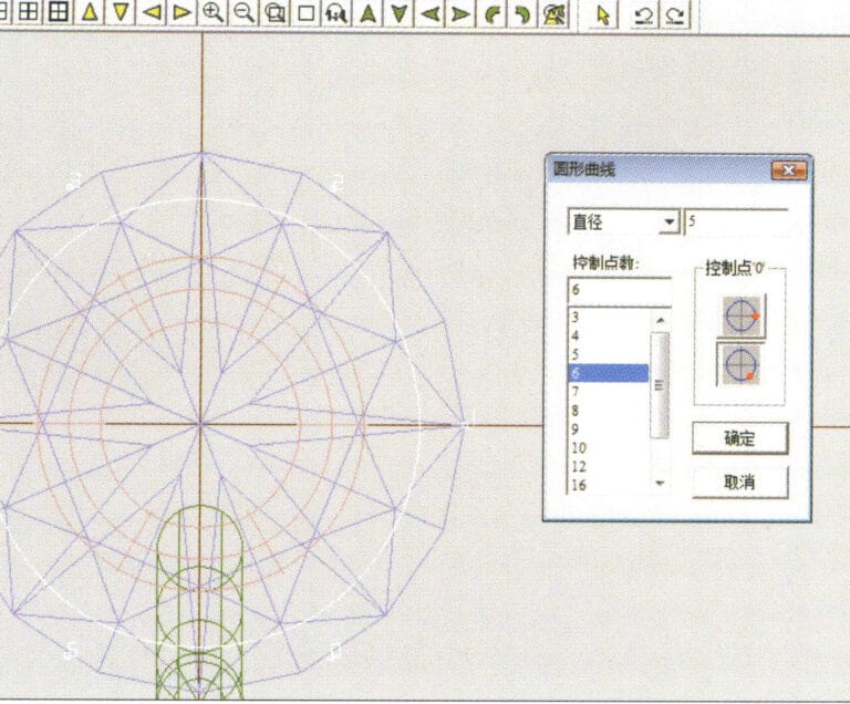
11. Select "Curve" > "Circular Curve" from the menu bar, enter the relevant values in the "Circular Curve" dialog box and confirm
11. Select "Curve" > "Circular Curve" from the menu bar, enter the relevant values in the "Circular Curve" dialog box and confirm

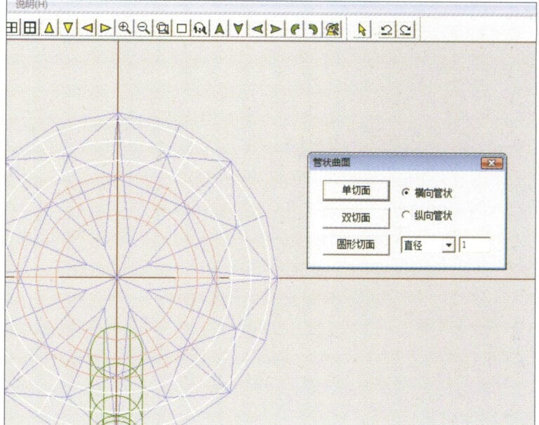
12. Select "Surface" > "Tubular Surface" from the menu bar, enter the relevant values and confirm
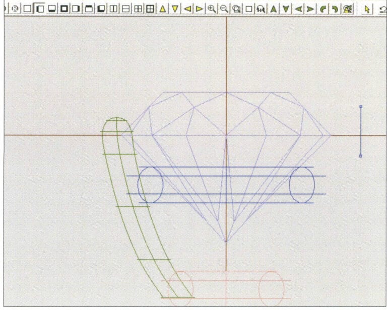
12. Select "Surface" > "Tubular Surface" from the menu bar, enter the relevant values and confirm

13. Select the menu bar "Edit" > "Move" to move the selected graphic

13. Select the menu bar "Edit" > "Move" to move the selected graphic

14. Select the completed claw shape, choose "Copy" > "Circular Copy" from the menu, enter the relevant values in the "Circular Copy" dialog box and confirm
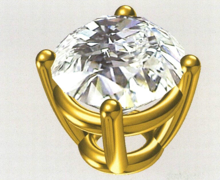
14. Select the completed claw shape, choose "Copy" > "Circular Copy" from the menu, enter the relevant values in the "Circular Copy" dialog box and confirm

15. Select "View" > "Shadow Map" from the menu bar to inspect the shadow effects
15. Select "View" > "Shadow Map" from the menu bar to inspect the shadow effects

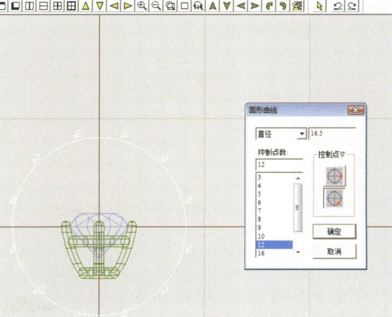
16. Select "Curve" > "Circular Curve" from the menu bar, enter the "Circular Curve" dialog box, and input the relevant values as the inner diameter of the ring shank
16. Select "Curve" > "Circular Curve" from the menu bar, enter the "Circular Curve" dialog box, and input the relevant values as the inner diameter of the ring shank

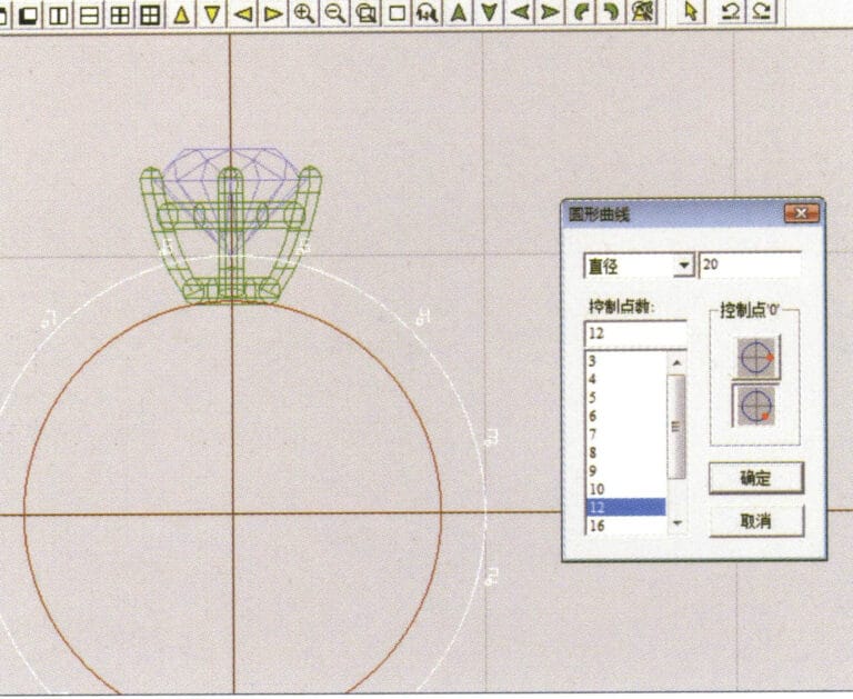
17. Select "Curve" > "Circular Curve" from the menu bar, enter the "Circular Curve" dialog box, and input the relevant values as the outer diameter of the ring shank

17. Select "Curve" > "Circular Curve" from the menu bar, enter the "Circular Curve" dialog box, and input the relevant values as the outer diameter of the ring shank

18. Select "Curve" > "Circular Curve" from the menu bar, enter the "Circular Curve" dialog box, and input the relevant values as the outer diameter of the engine-turned band
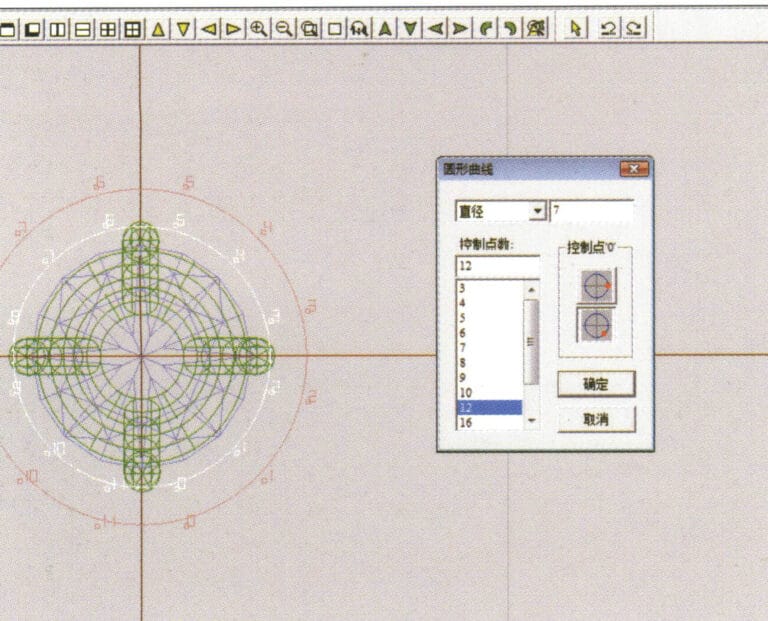
18. Select "Curve" > "Circular Curve" from the menu bar, enter the "Circular Curve" dialog box, and input the relevant values as the outer diameter of the engine-turned band

19. Select "Curve" > "Circular Curve" from the menu bar, enter the "Circular Curve" dialog box, and input the relevant values as the inner diameter of the engine-turned band
19. Select "Curve" > "Circular Curve" from the menu bar, enter the "Circular Curve" dialog box, and input the relevant values as the inner diameter of the engine-turned band

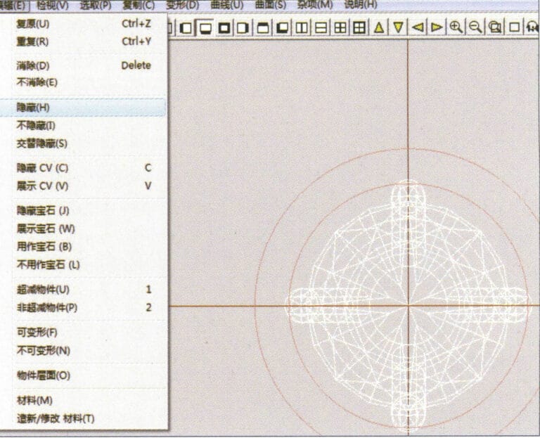
20. Select "Edit" > "Hide" from the menu bar to hide the completed gemstone inlay
20. Select "Edit" > "Hide" from the menu bar to hide the completed gemstone inlay

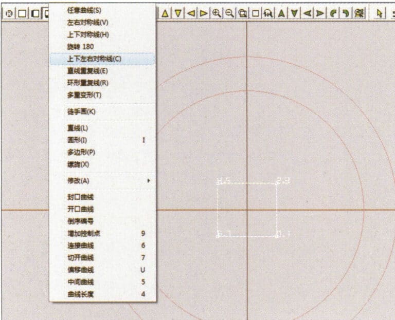
21. Select "Curve" > "Vertical and Horizontal Symmetry Line" from the menu bar
21. Select "Curve" > "Vertical and Horizontal Symmetry Line" from the menu bar

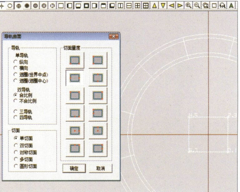
22. Select "Surface" > "Rail Surface" from the menu bar to enter the "Rail Surface" dialog box, select the relevant options and confirm
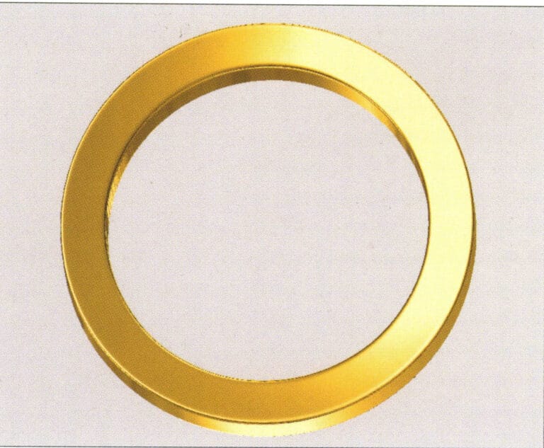
22. Select "Surface" > "Rail Surface" from the menu bar to enter the "Rail Surface" dialog box, select the relevant options and confirm

23. Select "View" > "Shadow Map" from the menu bar to inspect the shadow effects
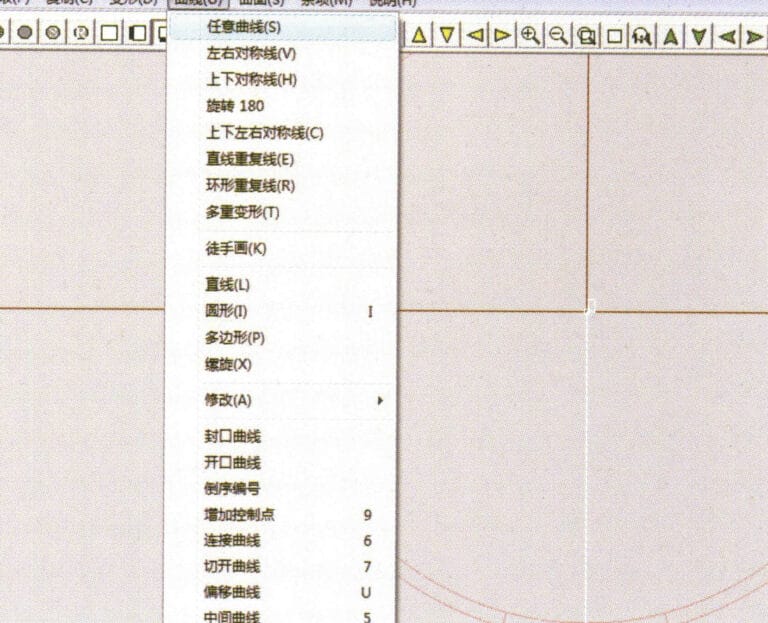
23. Select "View" > "Shadow Map" from the menu bar to inspect the shadow effects

24. Select "Curve" > "Freeform Curve" from the menu bar to draw a guideline

24. Select "Curve" > "Freeform Curve" from the menu bar to draw a guideline

25. Select "Copy" > "Hide Copy" from the menu bar to copy the already drawn auxiliary lines
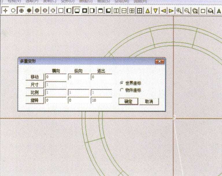
25. Select "Copy" > "Hide Copy" from the menu bar to copy the already drawn auxiliary lines

26. Select “Deformation” > “Multiple Deformation” in the menu bar to enter the “Multiple Deformation” dialog box, enter the relevant values and confirm
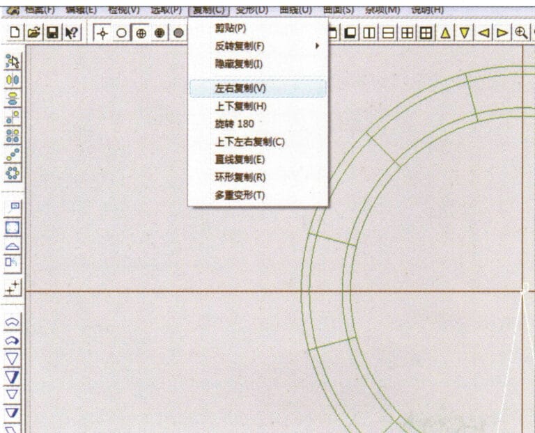
26. Select “Deformation” > “Multiple Deformation” in the menu bar to enter the “Multiple Deformation” dialog box, enter the relevant values and confirm

27. Select “Copy” > “Copy Up and Down” in the menu bar to copy the drawn auxiliary lines
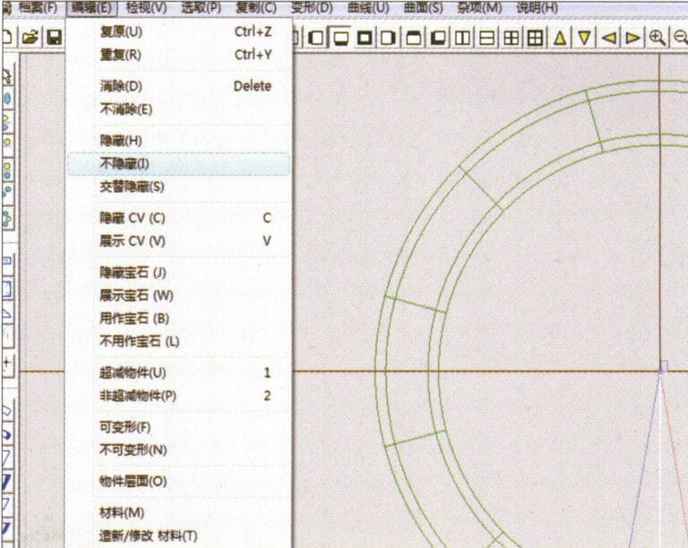
27. Select “Copy” > “Copy Up and Down” in the menu bar to copy the drawn auxiliary lines

28. Select "Edit" > "Unhide" from the menu to display the hidden curves
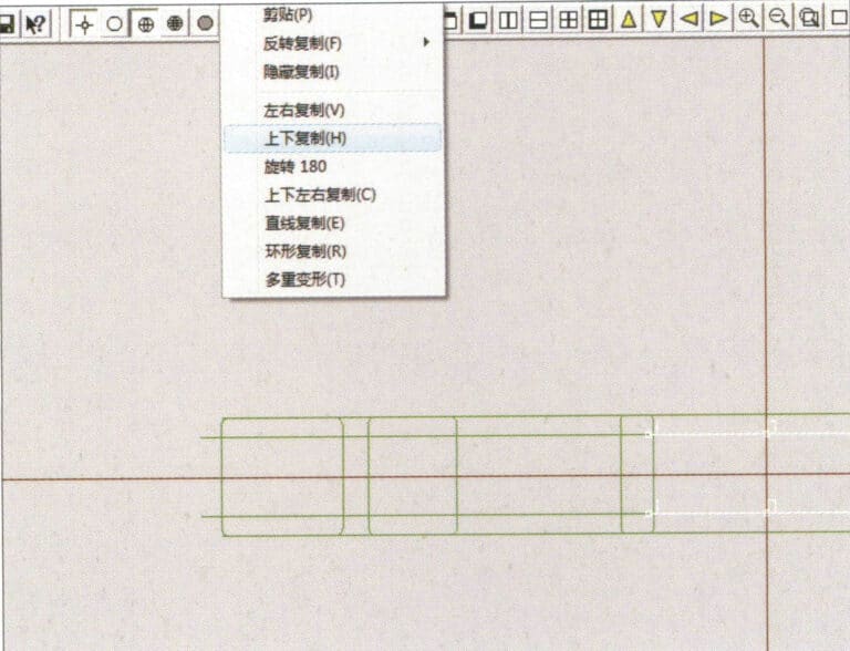
28. Select "Edit" > "Unhide" from the menu to display the hidden curves

29. Select "Copy" > "Copy Up and Down" from the menu bar to copy the selected curve
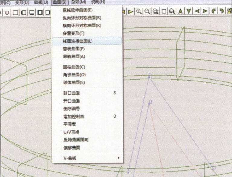
29. Select "Copy" > "Copy Up and Down" from the menu bar to copy the selected curve

30. Select curves/surfaces in a clockwise direction to create line-surface connections, then select "Surface" > "Cap Surface" from the menu bar
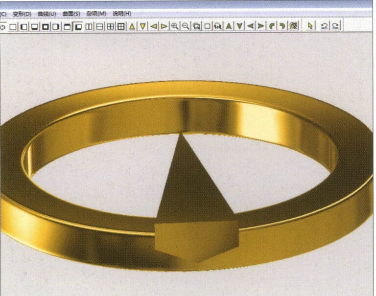
30. Select curves/surfaces in a clockwise direction to create line-surface connections, then select "Surface" > "Cap Surface" from the menu bar

31. Select "View" > "Shadow Map" from the menu bar to inspect the shadow effects
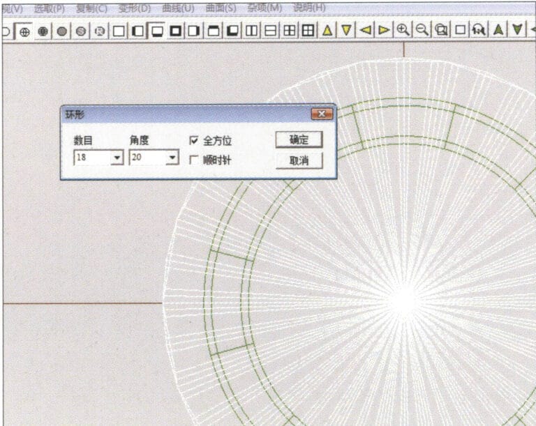
31. Select "View" > "Shadow Map" from the menu bar to inspect the shadow effects

32. Select "Copy" > "Circular Copy" from the menu bar, enter the relevant values and confirm
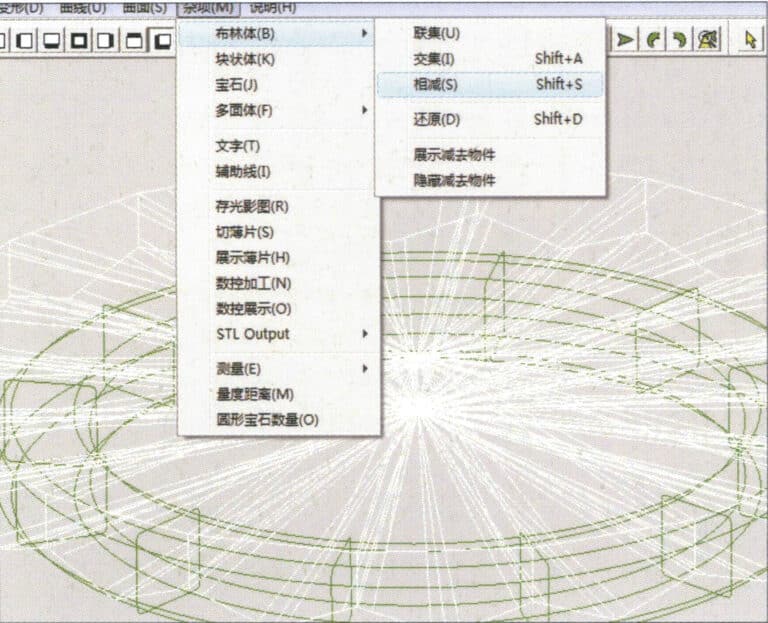
32. Select "Copy" > "Circular Copy" from the menu bar, enter the relevant values and confirm

33. Select "Miscellaneous" > "Boolean" > "Subtract" from the menu bar to subtract the selected surface from the already united surface
33. Select "Miscellaneous" > "Boolean" > "Subtract" from the menu bar to subtract the selected surface from the already united surface

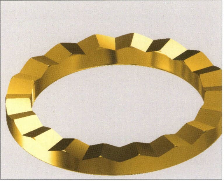
34. Select "View" > "Shadow Map" from the menu bar to inspect the shadow effects
34. Select "View" > "Shadow Map" from the menu bar to inspect the shadow effects

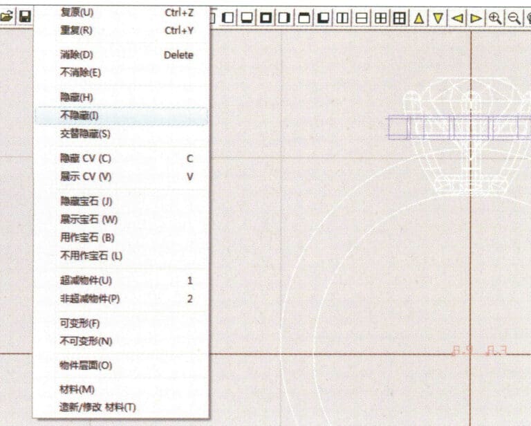
35. Select "Edit" > "Unhide" from the menu bar to display the hidden objects
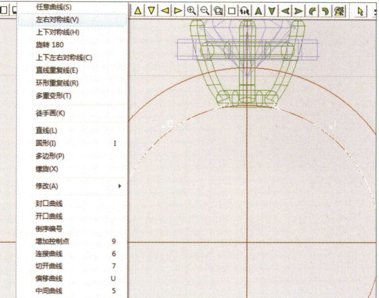
35. Select "Edit" > "Unhide" from the menu bar to display the hidden objects

36. Select "Curve" > "Left-Right Symmetry Line" from the menu bar to draw the inner diameter of the ring wall
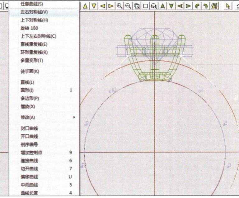
36. Select "Curve" > "Left-Right Symmetry Line" from the menu bar to draw the inner diameter of the ring wall

37. Select "Curve" > "Left-Right Symmetry Line" from the menu bar to draw the outer diameter of the ring wall
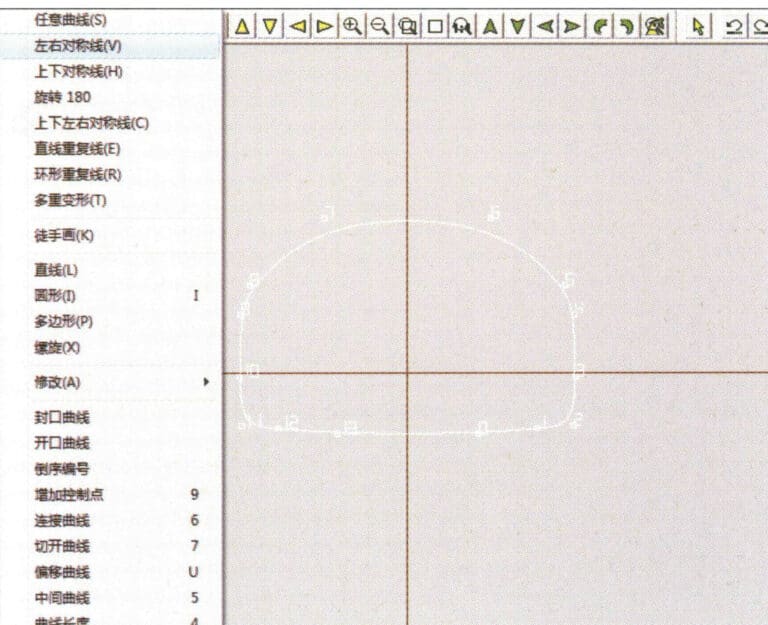
37. Select "Curve" > "Left-Right Symmetry Line" from the menu bar to draw the outer diameter of the ring wall

38. Select “Curve” > “Left-Right Symmetry Line” in the menu bar to draw a cutout of the ring shank
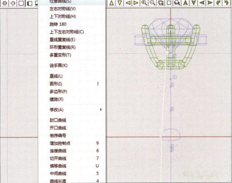
38. Select “Curve” > “Left-Right Symmetry Line” in the menu bar to draw a cutout of the ring shank

39. Select "Curve" > "Freeform Curve" from the menu bar to draw a guideline
39. Select "Curve" > "Freeform Curve" from the menu bar to draw a guideline

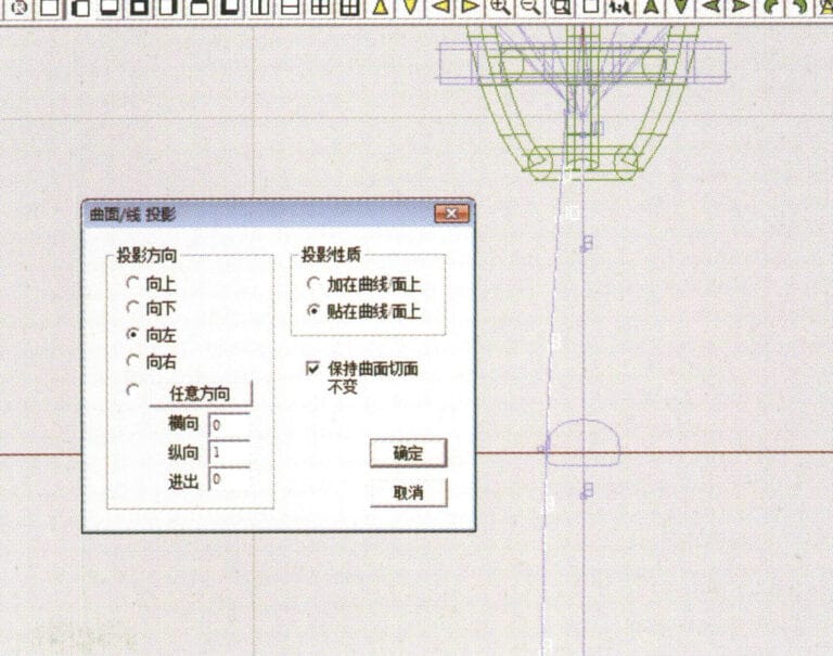
40. Select "Deformation" > "Surface/Line Projection" from the menu bar to enter the "Surface/Line Projection" dialog box, input the relevant values and confirm
40. Select "Deformation" > "Surface/Line Projection" from the menu bar to enter the "Surface/Line Projection" dialog box, input the relevant values and confirm

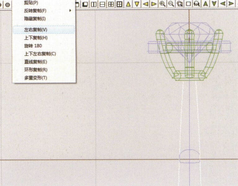
41. Select "Copy" > "Copy Left and Right" from the menu bar to copy the inner diameter of the ring shank
41. Select "Copy" > "Copy Left and Right" from the menu bar to copy the inner diameter of the ring shank

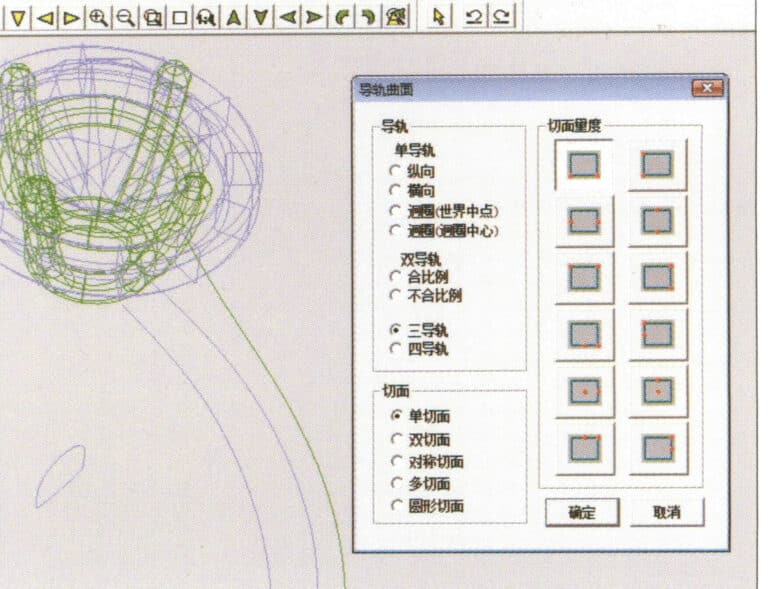
42. Select "Surface" > "Rail Surface" from the menu bar to enter the "Rail Surface" dialog box, select the relevant options and confirm
42. Select "Surface" > "Rail Surface" from the menu bar to enter the "Rail Surface" dialog box, select the relevant options and confirm

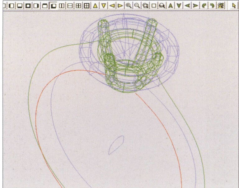
43. Select a curve as the left guide rail, and then select a curve as the right guide rail

43. Select a curve as the left guide rail, and then select a curve as the right guide rail

44. Select a curve as the upper guide rail
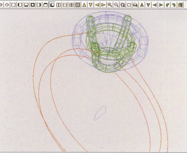
44. Select a curve as the upper guide rail

45. Select a curve as the cross-section of the guide surface.
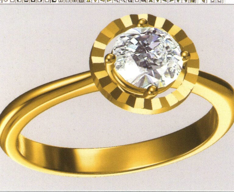
45. Select a curve as the cross-section of the guide surface.

46. Select "View" > "Light and Shadow Map" from the menu bar to examine the light and shadow effects 47. Select "File" > "Save As" from the menu bar to save the file

46. Select "View" > "Light and Shadow Map" from the menu bar to examine the light and shadow effects

47. Select "File" > "Save As" from the menu bar to save the file

2. Pearl Ring

Pearl Ring

Etapele de producție sunt următoarele:
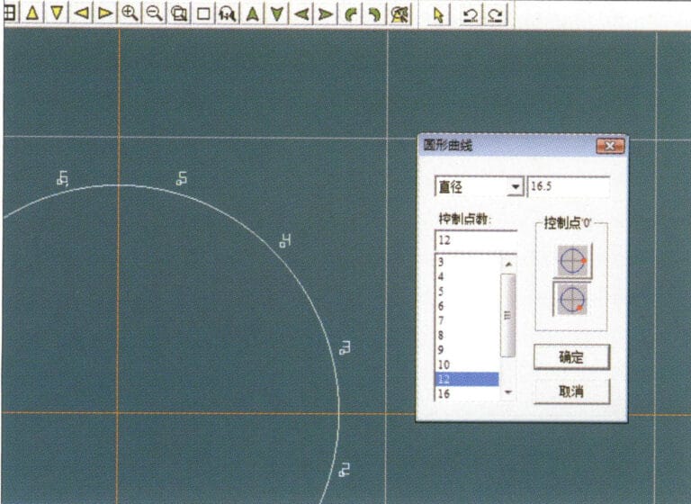
1. Create a new file in JewelCAD, select "Curve" > "Circular Curve" from the menu bar, enter the relevant values in the "Circular Curve" dialog box as the outer curve of the ring, and confirm
1. Create a new file in JewelCAD, select "Curve" > "Circular Curve" from the menu bar, enter the relevant values in the "Circular Curve" dialog box as the outer curve of the ring, and confirm

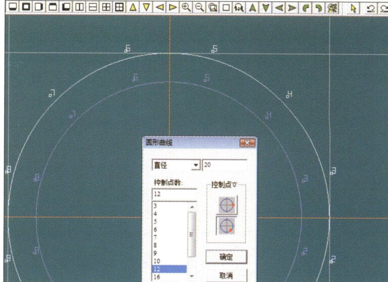
2. Select "Curve" > "Circular Curve" from the menu bar, enter the relevant values in the "Circular Curve" dialog box to set the inner curve of the ring, and confirm
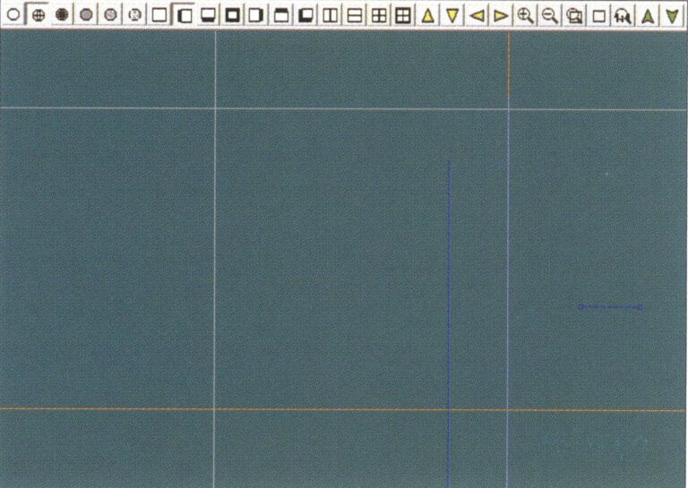
2. Select "Curve" > "Circular Curve" from the menu bar, enter the relevant values in the "Circular Curve" dialog box to set the inner curve of the ring, and confirm

3. Select "Edit" > "Move" from the menu bar to move the selected inner curve of the ring
3. Select "Edit" > "Move" from the menu bar to move the selected inner curve of the ring

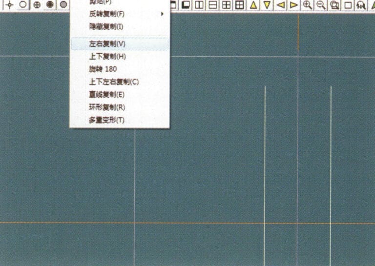
4. Select "Copy" > "Copy Left and Right" from the menu bar to copy the curve of the inner circle of the ring
4. Select "Copy" > "Copy Left and Right" from the menu bar to copy the curve of the inner circle of the ring

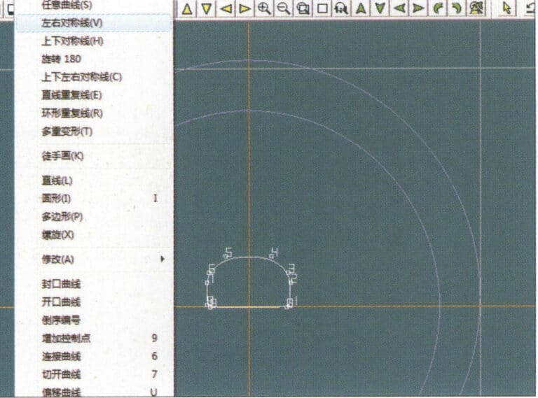
5. Select "Curve" > "Left-Right Symmetry Line" from the menu bar as the cross-section of the ring band
5. Select "Curve" > "Left-Right Symmetry Line" from the menu bar as the cross-section of the ring band

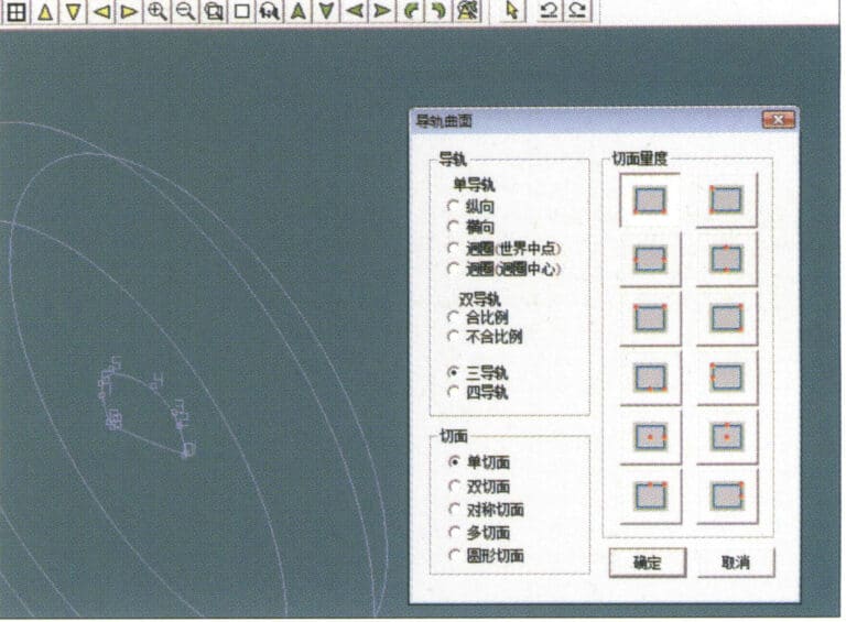
6. Select "Curved Surface" > "Guide Rail Surface" from the menu bar, enter the "Guide Rail Surface" dialog box, select the relevant options and confirm
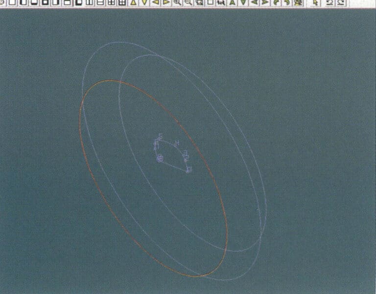
6. Select "Curved Surface" > "Guide Rail Surface" from the menu bar, enter the "Guide Rail Surface" dialog box, select the relevant options and confirm

7. Choose a curve as the right guide rail
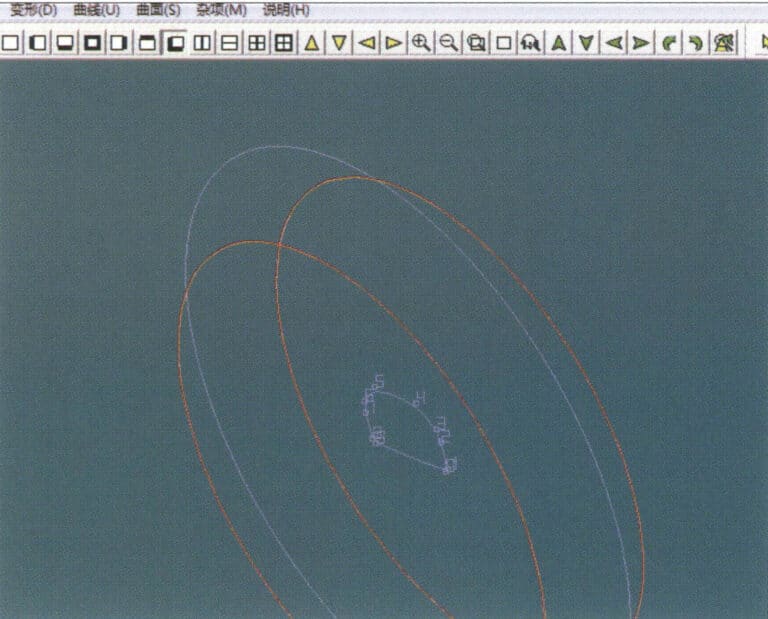
7. Choose a curve as the right guide rail

8. Choose a curve as the upper guide rail
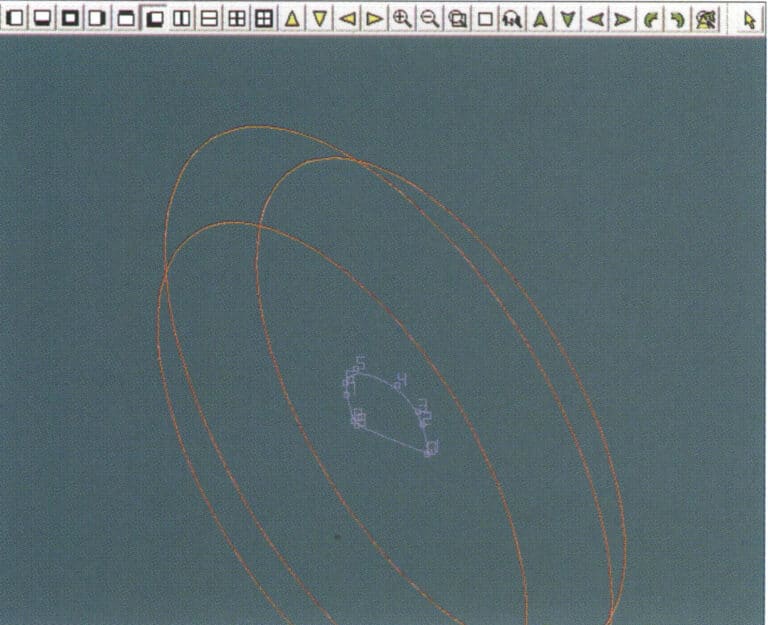
8. Choose a curve as the upper guide rail

9. Select the cross-section of the ring band as the cross-section of the guide curve surface
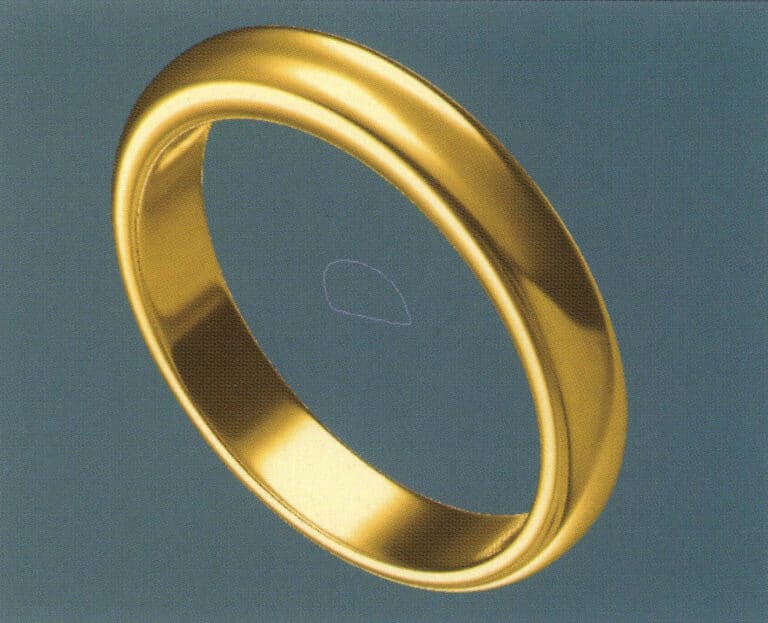
9. Select the cross-section of the ring band as the cross-section of the guide curve surface

10. Select "View" > "Shadow Map" from the menu bar to inspect the shadow effects
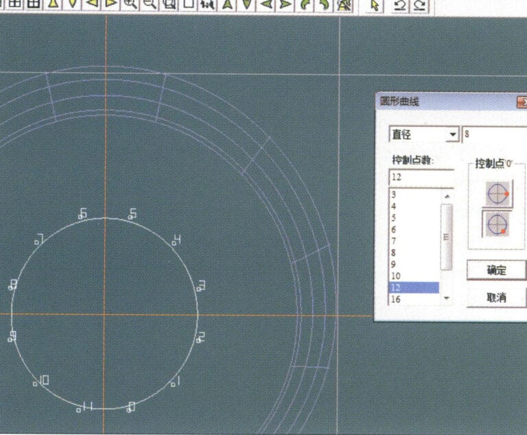
10. Select "View" > "Shadow Map" from the menu bar to inspect the shadow effects

11. Select "Curve" > "Circular Curve" from the menu bar, enter the relevant values in the "Circular Curve" dialog box as auxiliary lines, and confirm
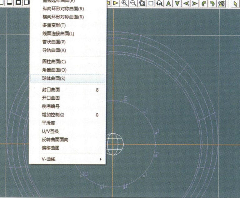
11. Select "Curve" > "Circular Curve" from the menu bar, enter the relevant values in the "Circular Curve" dialog box as auxiliary lines, and confirm

12. Select "Surface" > "Spherical Surface" from the menu bar
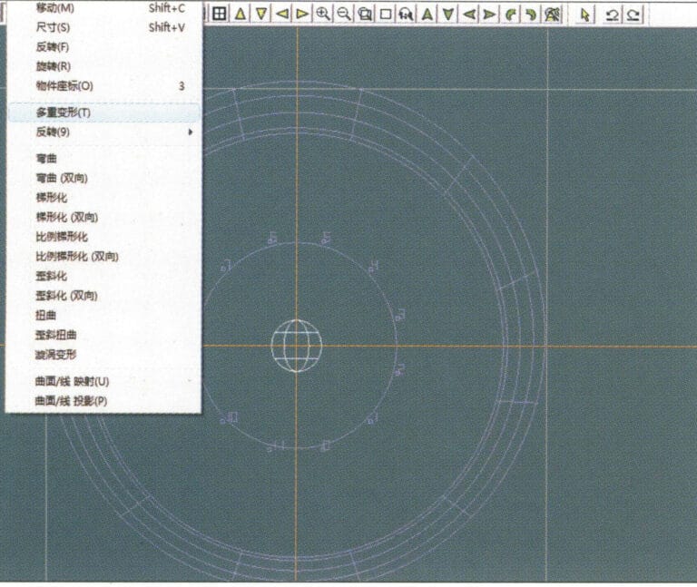
12. Select "Surface" > "Spherical Surface" from the menu bar

13. Select "Deformation" > "Multiple Deformation" from the menu bar to enlarge the sphere
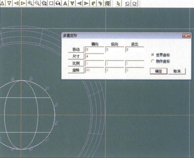
13. Select "Deformation" > "Multiple Deformation" from the menu bar to enlarge the sphere

14. Enter the "Multiple Deformation" dialog box, input the corresponding values to enlarge the sphere to the width of the guidelines, and confirm
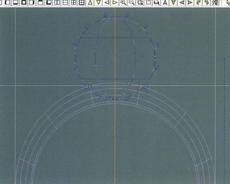
14. Enter the "Multiple Deformation" dialog box, input the corresponding values to enlarge the sphere to the width of the guidelines, and confirm

15. Select "Edit" > "Move" from the menu bar to move both the sphere and the auxiliary line simultaneously
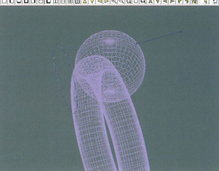
15. Select "Edit" > "Move" from the menu bar to move both the sphere and the auxiliary line simultaneously

16. Select "Edit" > "Move" from the menu bar to remove the guidelines
16. Select "Edit" > "Move" from the menu bar to remove the guidelines

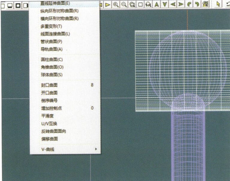
17. Select "Surface" > "Straight Line Extend Surface" from the menu bar to extend the auxiliary line into an auxiliary surface
17. Select "Surface" > "Straight Line Extend Surface" from the menu bar to extend the auxiliary line into an auxiliary surface

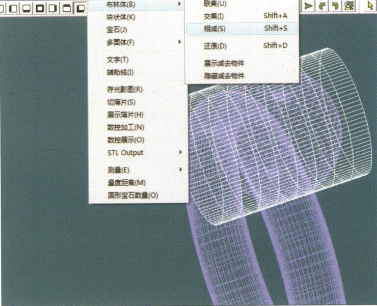
18. Select "Miscellaneous" > "Boolean" > "Subtract" from the menu bar to subtract the corresponding parts of the auxiliary surface ring
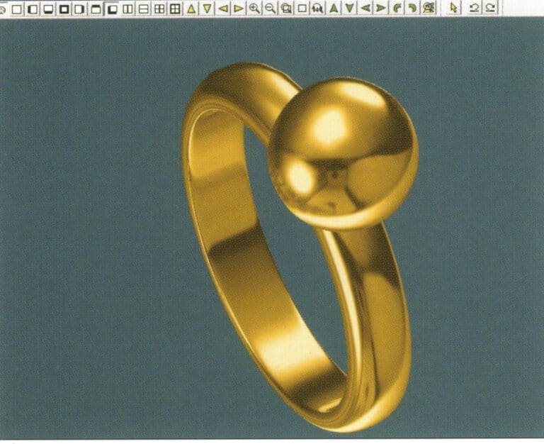
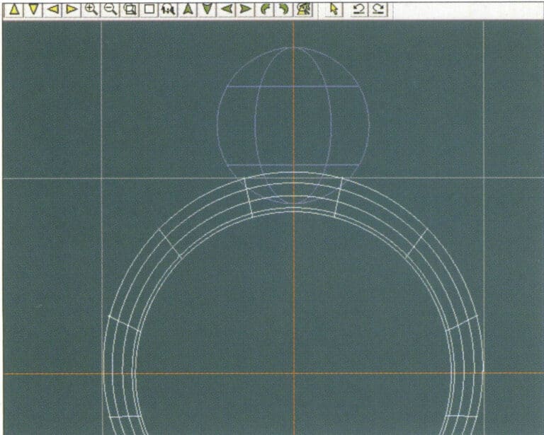
18. Select "Miscellaneous" > "Boolean" > "Subtract" from the menu bar to subtract the corresponding parts of the auxiliary surface ring

19. Select "View" > "Shadow Map" from the menu bar to inspect the shadow effects
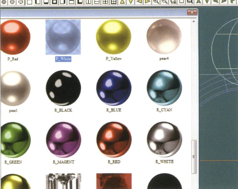
19. Select "View" > "Shadow Map" from the menu bar to inspect the shadow effects

20. Select the sphere, go to the menu bar and choose "Edit" > "Materials", enter the "Materials" dialog box, select the white pearl material and confirm
20. Select the sphere, go to the menu bar and choose "Edit" > "Materials", enter the "Materials" dialog box, select the white pearl material and confirm

21. Select the ring band, then choose "Edit" > "Materials" from the menu bar
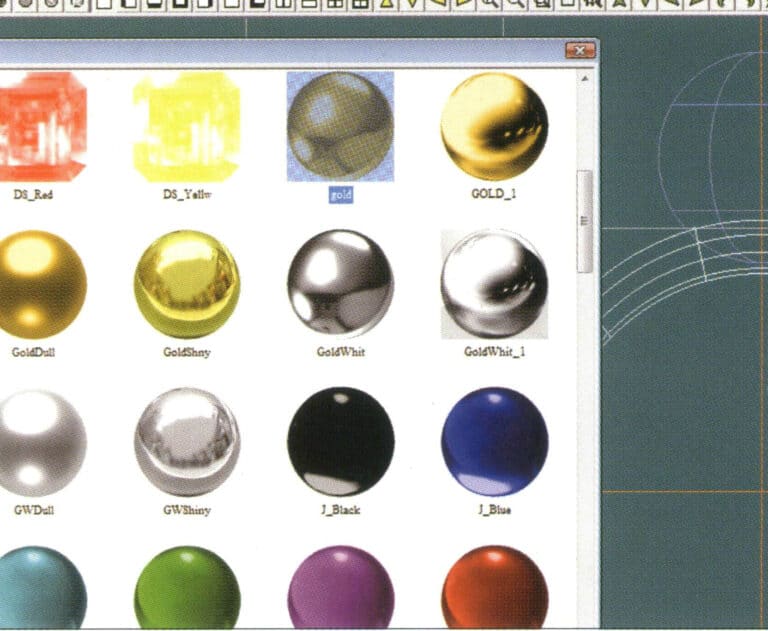
21. Select the ring band, then choose "Edit" > "Materials" from the menu bar

22. Enter the "Materials" dialog box, select the appropriate material, and confirm
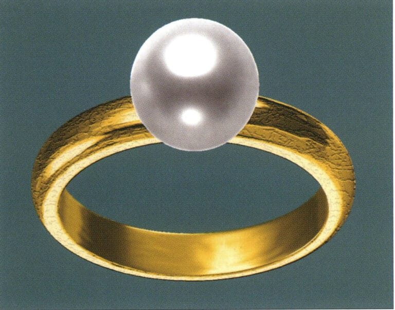
22. Enter the "Materials" dialog box, select the appropriate material, and confirm

23. Select "View" > "Shadow Map" from the menu bar to examine the light and shadow effects 24. Select "File" > "Save As" from the menu bar to save the file

23. Select "View" > "Shadow Map" from the menu bar to examine the light and shadow effects

24. Select "File" > "Save As" from the menu bar to save the file

3. Black Gold Pendant with Diamond Accents

Black Gold Pendant with Diamond Accents

Etapele de producție sunt următoarele:
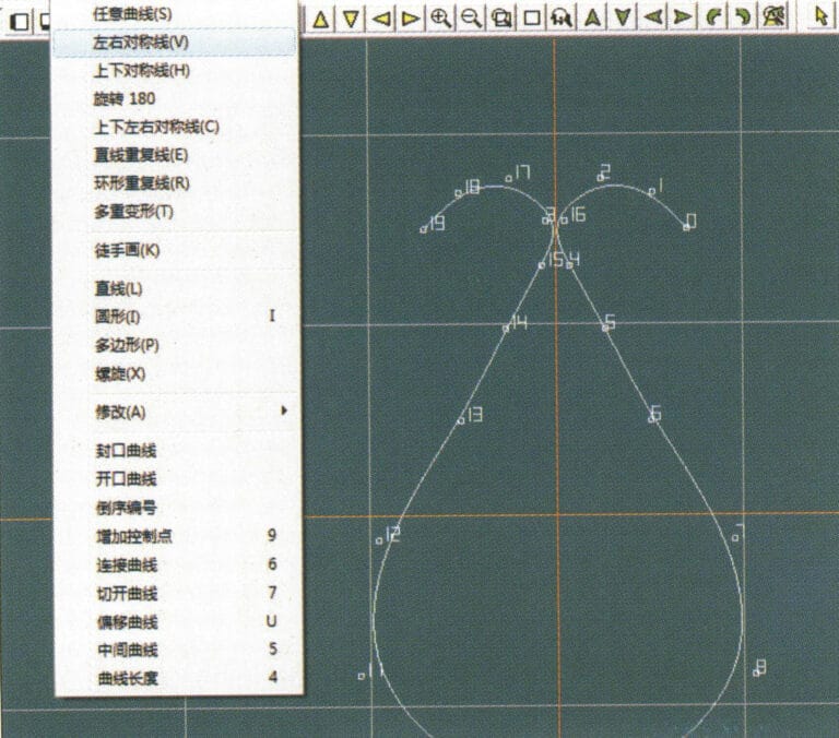
1. Create a new file in JewelCAD, select "Curve" > "Left-Right Symmetrical Line" from the menu bar, and draw the inner contour line of the pendant
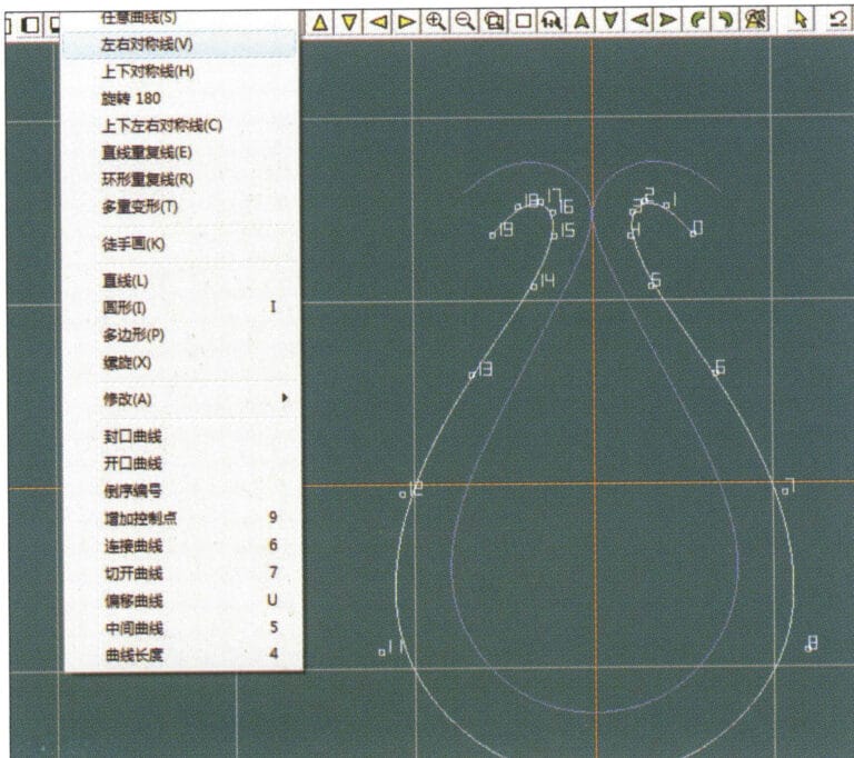
1. Create a new file in JewelCAD, select "Curve" > "Left-Right Symmetrical Line" from the menu bar, and draw the inner contour line of the pendant

2. Select "Curve" > "Left-Right Symmetrical Line" from the menu bar to draw the outer contour line of the pendant (note that the control points of the inner contour line and the outer contour line should have the same direction and quantity).
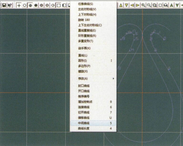
2. Select "Curve" > "Left-Right Symmetrical Line" from the menu bar to draw the outer contour line of the pendant (note that the control points of the inner contour line and the outer contour line should have the same direction and quantity).

3. Select "Curve" > "Middle Curve" from the menu bar
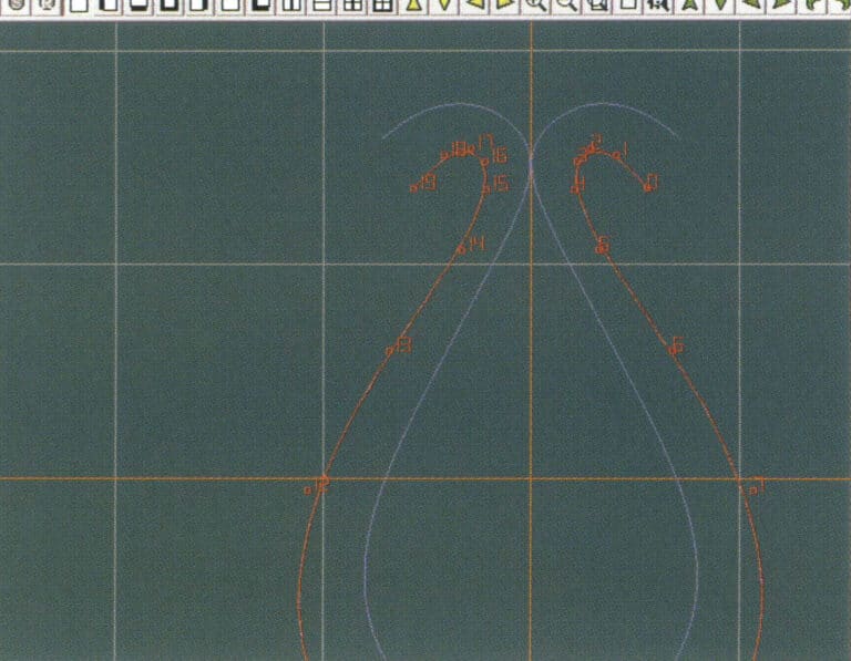
3. Select "Curve" > "Middle Curve" from the menu bar

4. Select two curves to create the middle curve. First, select the outer contour line
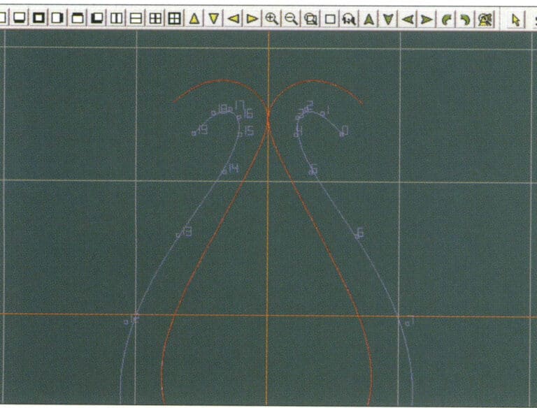
4. Select two curves to create the middle curve. First, select the outer contour line

5. Select two curves to create the middle curve, then select the inner contour line
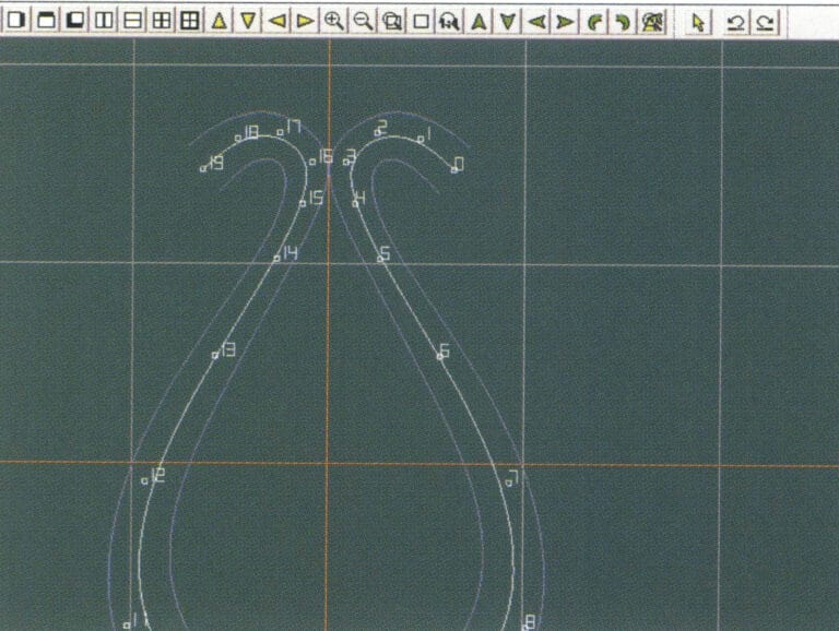
5. Select two curves to create the middle curve, then select the inner contour line

6. View the already created intermediate curves
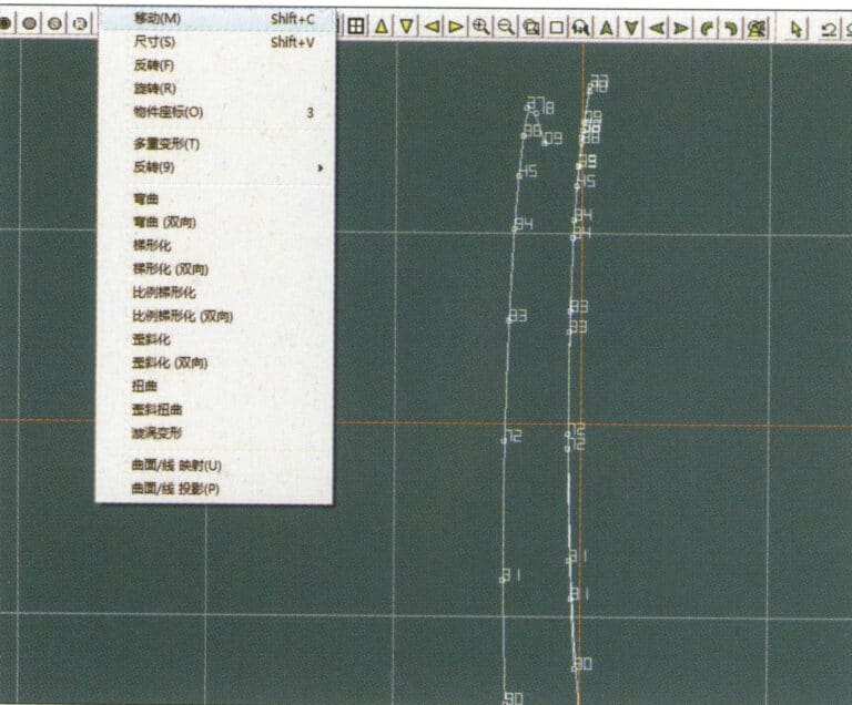
6. View the already created intermediate curves

7. Select "Deformation" > "Move" from the menu bar to move the CV and the CV of the contour line
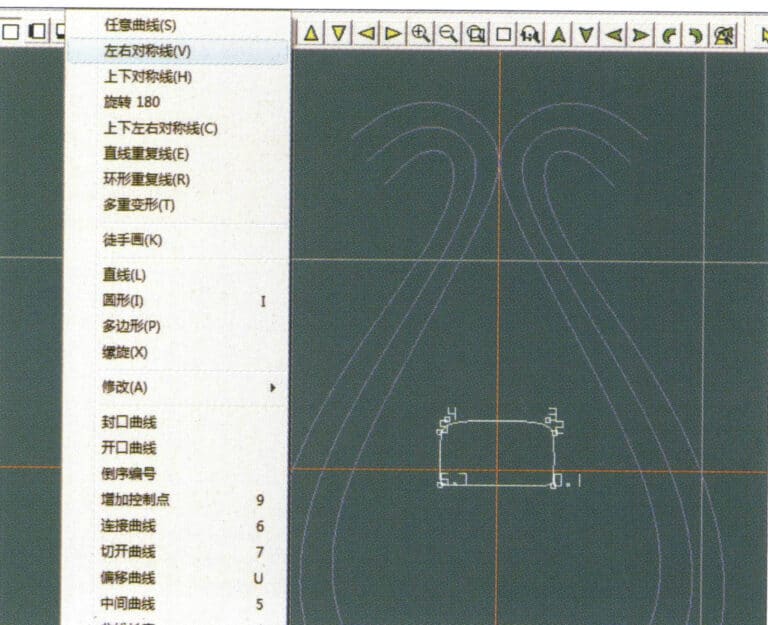
7. Select "Deformation" > "Move" from the menu bar to move the CV and the CV of the contour line

8. Select "Curve" > "Left-Right Symmetry Line" from the menu bar to create a cross-section
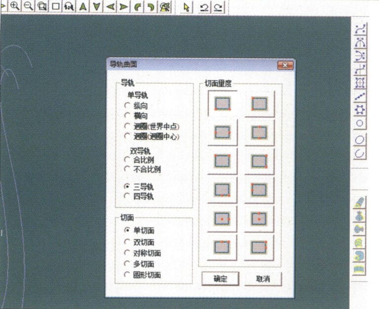
8. Select "Curve" > "Left-Right Symmetry Line" from the menu bar to create a cross-section

9. Select "Surface" > "Rail Surface" from the menu bar, enter the "Rail Surface" dialog box to select the relevant options, and confirm; select a curve as the left curve, starting from the left curve in a clockwise direction, left-click on the curve as the rail, and then select another curve as the section of the rail surface
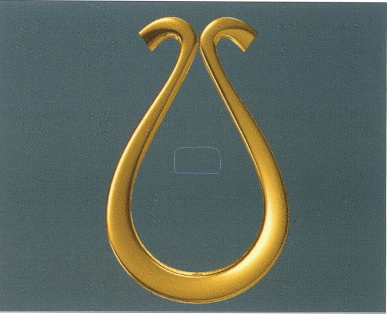
9. Select "Surface" > "Rail Surface" from the menu bar, enter the "Rail Surface" dialog box to select the relevant options, and confirm; select a curve as the left curve, starting from the left curve in a clockwise direction, left-click on the curve as the rail, and then select another curve as the section of the rail surface

10. Select "View" > "Shadow Map" from the menu bar to inspect the shadow effects
10. Select "View" > "Shadow Map" from the menu bar to inspect the shadow effects

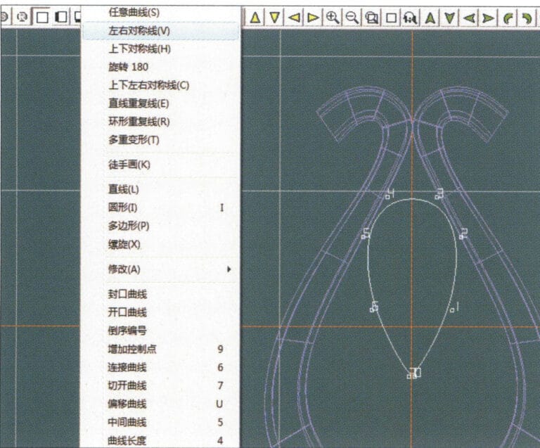
11. Select "Curve" > "Left-Right Symmetry Line" from the menu bar to draw the outer contour line of the seed-shaped toggle
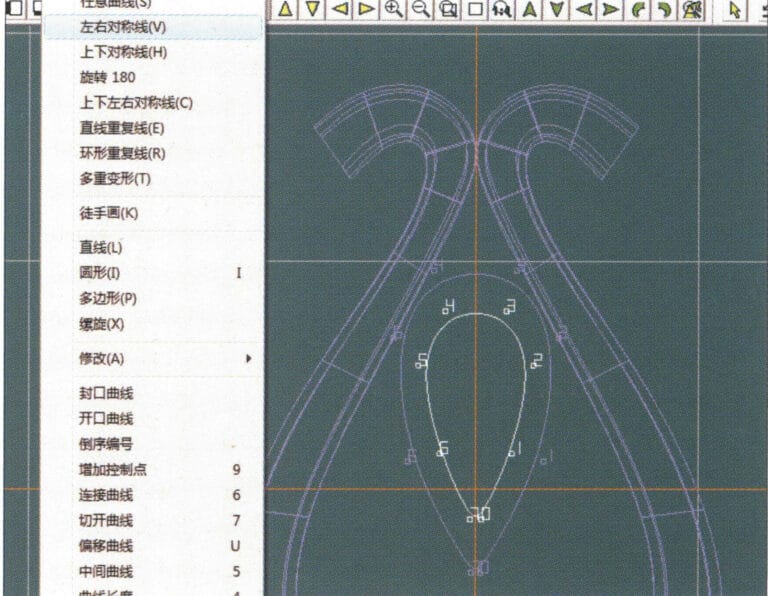
11. Select "Curve" > "Left-Right Symmetry Line" from the menu bar to draw the outer contour line of the seed-shaped toggle

12. Select "Curve" > "Left-Right Symmetry Line" from the menu bar to draw the inner contour line of the seed-shaped toggle
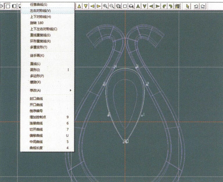
12. Select "Curve" > "Left-Right Symmetry Line" from the menu bar to draw the inner contour line of the seed-shaped toggle

13. Select "Curve" > "Left-Right Symmetry Line" from the menu bar, and draw the lower dark line of the center of the seed-shaped toggle
13. Select "Curve" > "Left-Right Symmetry Line" from the menu bar, and draw the lower dark line of the center of the seed-shaped toggle

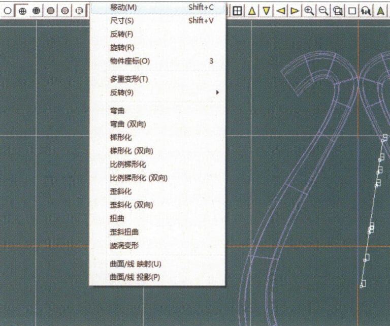
14. Select "Deformation" > "Move" from the menu bar to move the seed-shaped toggle CV
14. Select "Deformation" > "Move" from the menu bar to move the seed-shaped toggle CV

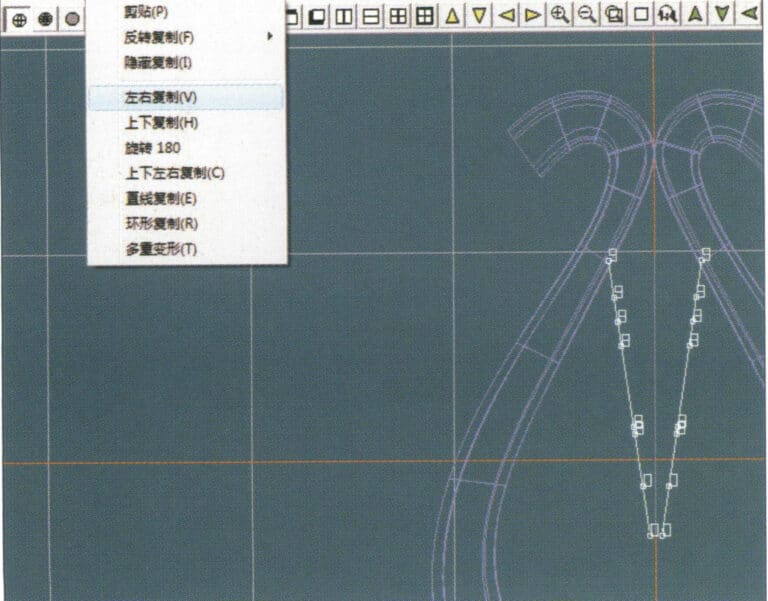
15. Select "Copy" > "Copy Left and Right" from the menu bar to copy the curve of the seed-shaped toggle
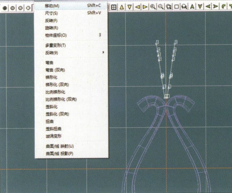
15. Select "Copy" > "Copy Left and Right" from the menu bar to copy the curve of the seed-shaped toggle

16. Select "Deformation" > "Move" from the menu bar to move the melon seed buckle curve
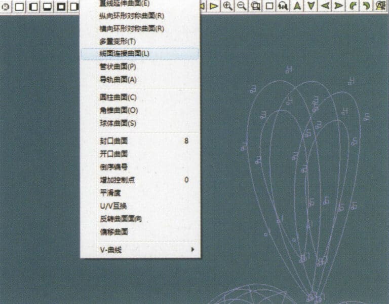
16. Select "Deformation" > "Move" from the menu bar to move the melon seed buckle curve

17. Select "Surface" > "Line-Surface Connection Surface" from the menu bar, and select the curve/surface in a clockwise direction to create a line-surface connection surface, then select "Curve" > "Closed Surface" from the menu bar
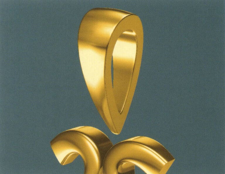
17. Select "Surface" > "Line-Surface Connection Surface" from the menu bar, and select the curve/surface in a clockwise direction to create a line-surface connection surface, then select "Curve" > "Closed Surface" from the menu bar

18. Select "View" > "Shadow Map" from the menu bar to examine the shadow effects
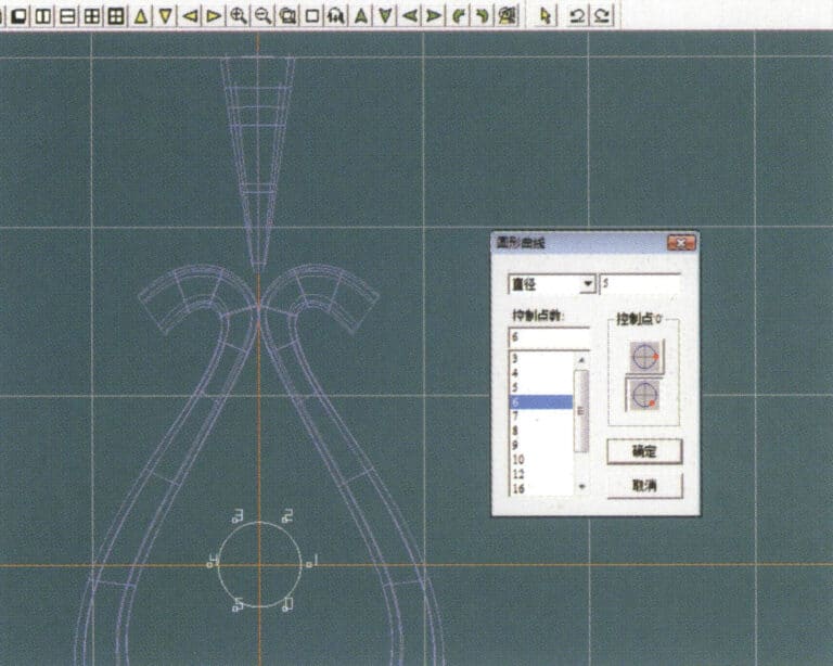
18. Select "View" > "Shadow Map" from the menu bar to examine the shadow effects

19. Select "Curve" > "Circular Curve" from the menu bar, enter the relevant values and confirm

19. Select "Curve" > "Circular Curve" from the menu bar, enter the relevant values and confirm

20. Select "Surface" > "Tubular Surface" from the menu bar
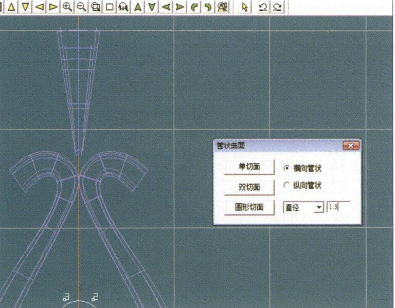
20. Select "Surface" > "Tubular Surface" from the menu bar

21. Enter the "Tubular Surface" dialog box, input the relevant values, click on the circular section, and confirm
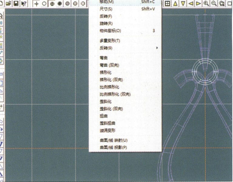
21. Enter the "Tubular Surface" dialog box, input the relevant values, click on the circular section, and confirm

22. Select "Deformation" > "Move" from the menu bar to move the ring buckle

22. Select "Deformation" > "Move" from the menu bar to move the ring buckle

23. Select "File" > "Insert File" from the menu bar
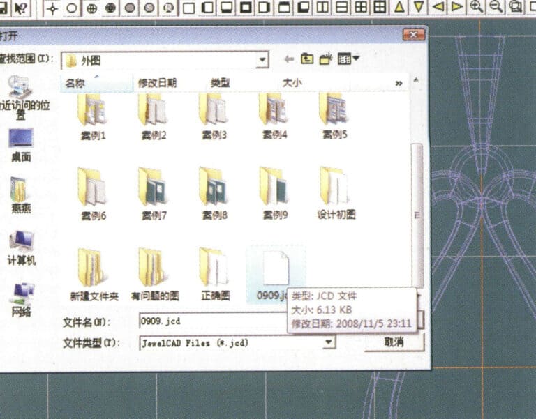
23. Select "File" > "Insert File" from the menu bar

24. Enter the "Insert File" dialog box, select the desired document and confirm
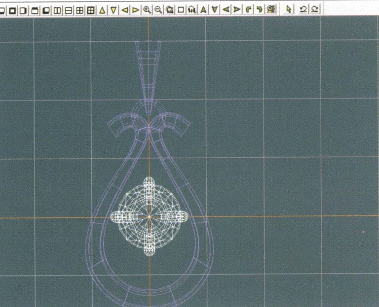
24. Enter the "Insert File" dialog box, select the desired document and confirm

25. View the inserted file - Gemstone
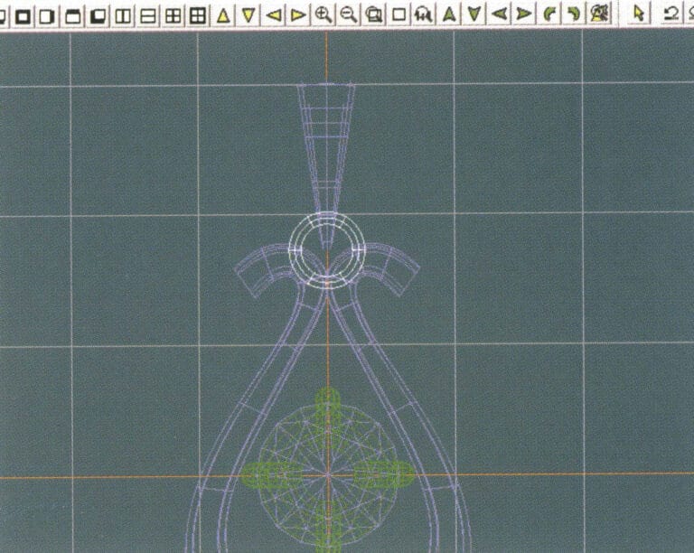
25. View the inserted file - Gemstone

26. Select "Copy" > "Copy Up and Down" from the menu bar to copy the selected toggle
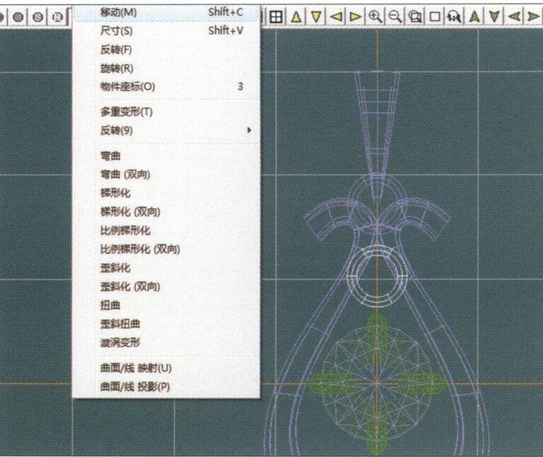
26. Select "Copy" > "Copy Up and Down" from the menu bar to copy the selected toggle

27. Select "Deformation" > "Move" from the menu bar to move the horizontal ring toggle
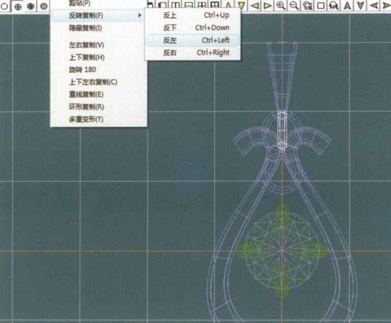
27. Select "Deformation" > "Move" from the menu bar to move the horizontal ring toggle

28. Select "Copy" > "Reverse Copy" > "Reverse Left" from the menu bar to create a vertical ring toggle
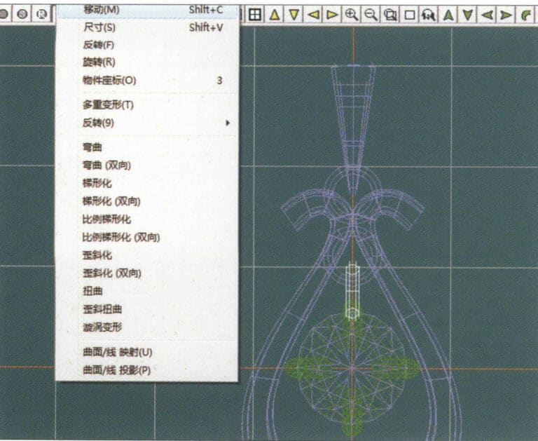
28. Select "Copy" > "Reverse Copy" > "Reverse Left" from the menu bar to create a vertical ring toggle

29. Select "Deformation" > "Move" from the menu bar to move the horizontal ring toggle
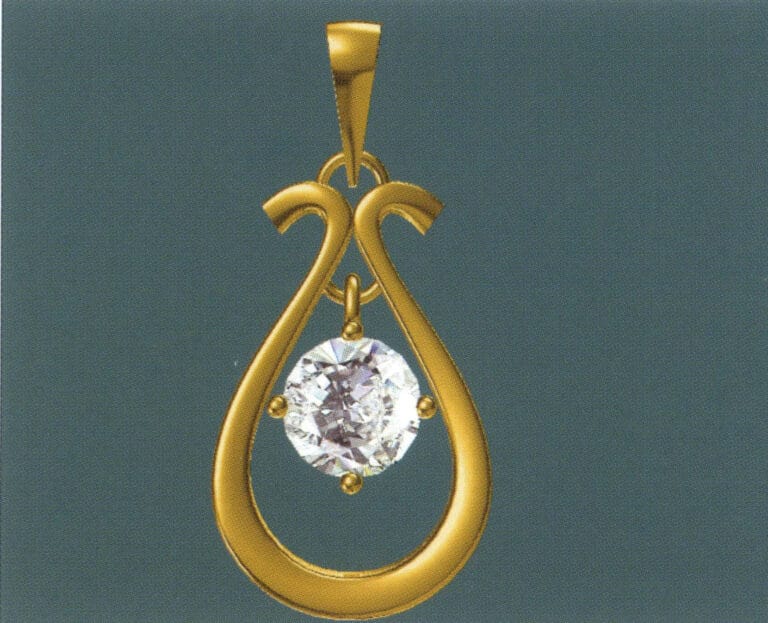
29. Select "Deformation" > "Move" from the menu bar to move the horizontal ring toggle

30. Select "View" > "Shadow Map" from the menu bar to examine the light and shadow effects
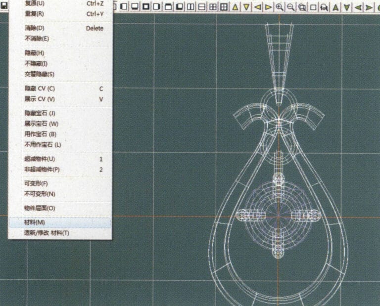
30. Select "View" > "Shadow Map" from the menu bar to examine the light and shadow effects

31. Select "Edit" > "Materials" from the menu bar to modify the materials of the selected object
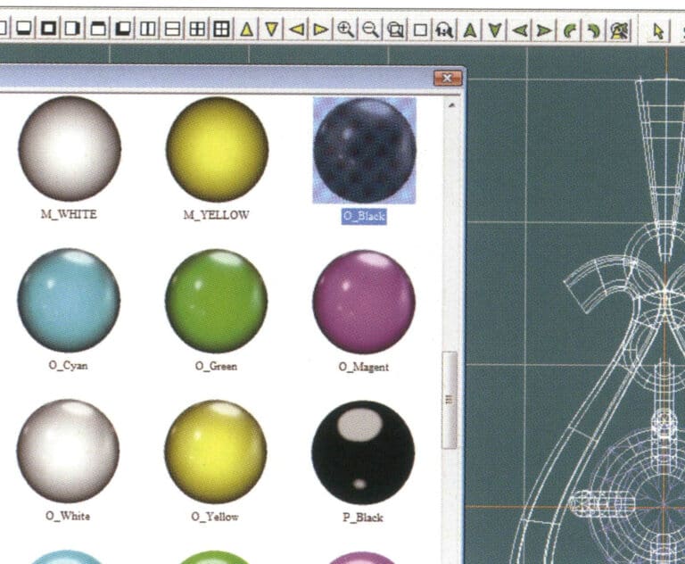
31. Select "Edit" > "Materials" from the menu bar to modify the materials of the selected object

32. Enter the "Materials" dialog box, select black gold and confirm
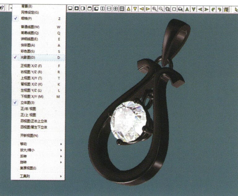
32. Enter the "Materials" dialog box, select black gold and confirm

33. Select "View" > "Shadow Map" from the menu bar to inspect the shadow effects 34. Select "File" > "Save As" from the menu bar to save the file

33. Select "View" > "Shadow Map" from the menu bar to inspect the shadow effects

34. Select "File" > "Save As" from the menu bar to save the file

4. Ruby Pendant
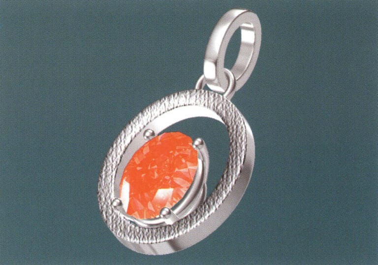
Ruby Pendant

Etapele de producție sunt următoarele:
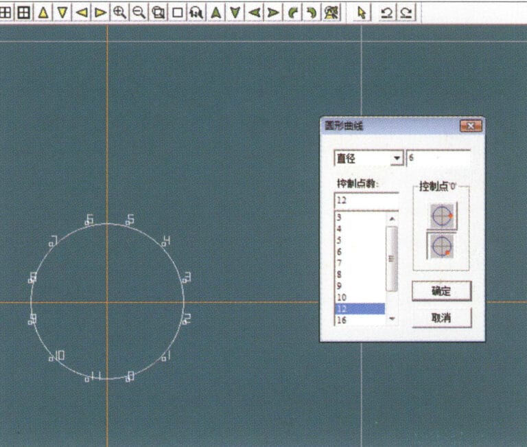
1. Create a new file in JewelCAD, select "Curve" > "Circular Curve" from the menu bar, enter the relevant values in the "Circular Curve" dialog box as the inner auxiliary line, and confirm

1. Create a new file in JewelCAD, select "Curve" > "Circular Curve" from the menu bar, enter the relevant values in the "Circular Curve" dialog box as the inner auxiliary line, and confirm

2. Select "Curve" > "Circular Curve" from the menu bar, enter the relevant values in the "Circular Curve" dialog box as the external auxiliary line, and confirm
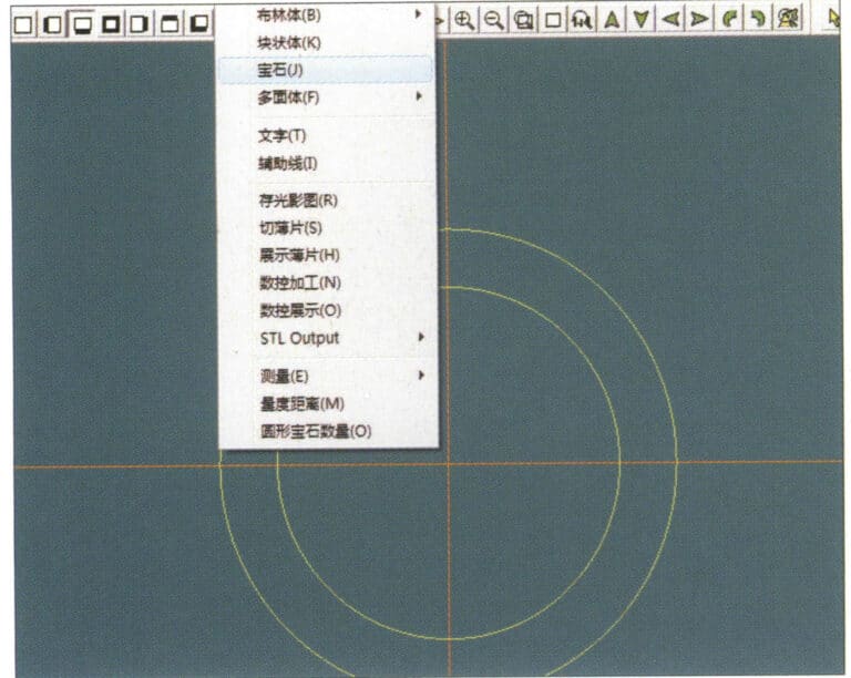
2. Select "Curve" > "Circular Curve" from the menu bar, enter the relevant values in the "Circular Curve" dialog box as the external auxiliary line, and confirm

3. Select "Miscellaneous" > "Gemstones" from the menu bar
3. Select "Miscellaneous" > "Gemstones" from the menu bar

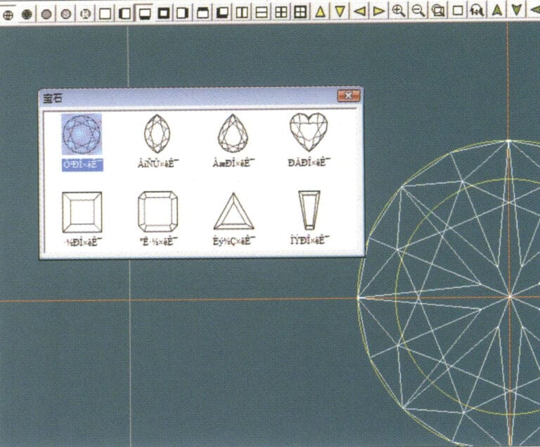
4. Enter the "Gem" dialog box, select the relevant gems and confirm
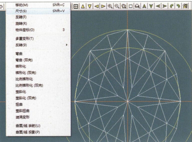
4. Enter the "Gem" dialog box, select the relevant gems and confirm

5. Select "Deformation" > "Size" from the menu bar to change the round gemstone into an oval gemstone
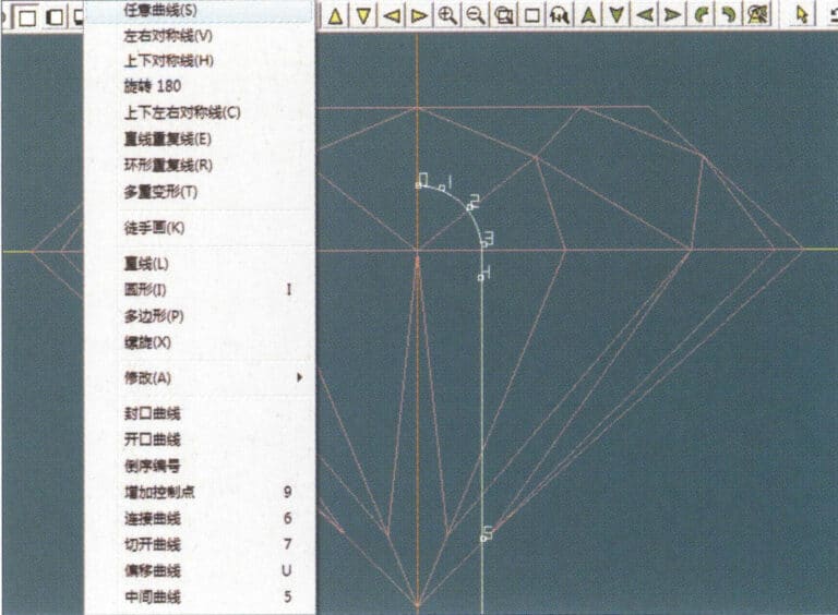
5. Select "Deformation" > "Size" from the menu bar to change the round gemstone into an oval gemstone

6. Select "Curve" > "Freeform Curve" from the menu bar to draw a claw-shaped guideline
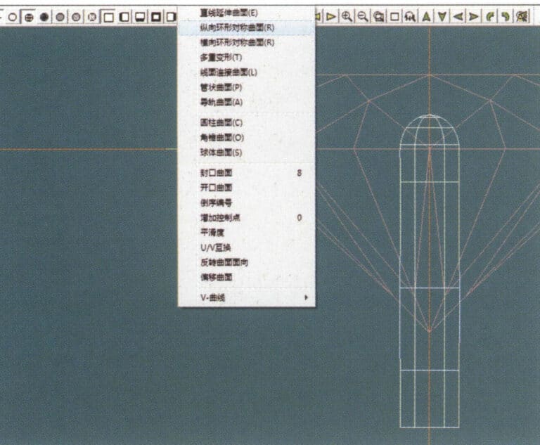
6. Select "Curve" > "Freeform Curve" from the menu bar to draw a claw-shaped guideline

7. Select "Surface" > "Longitudinal Circular Symmetrical Surface" from the menu bar, and draw a claw shape
7. Select "Surface" > "Longitudinal Circular Symmetrical Surface" from the menu bar, and draw a claw shape

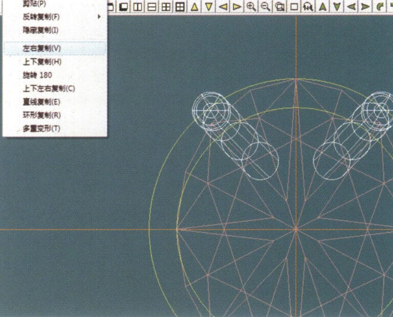
8. Select "Copy" > "Copy Left and Right" from the menu bar to copy the claw shape
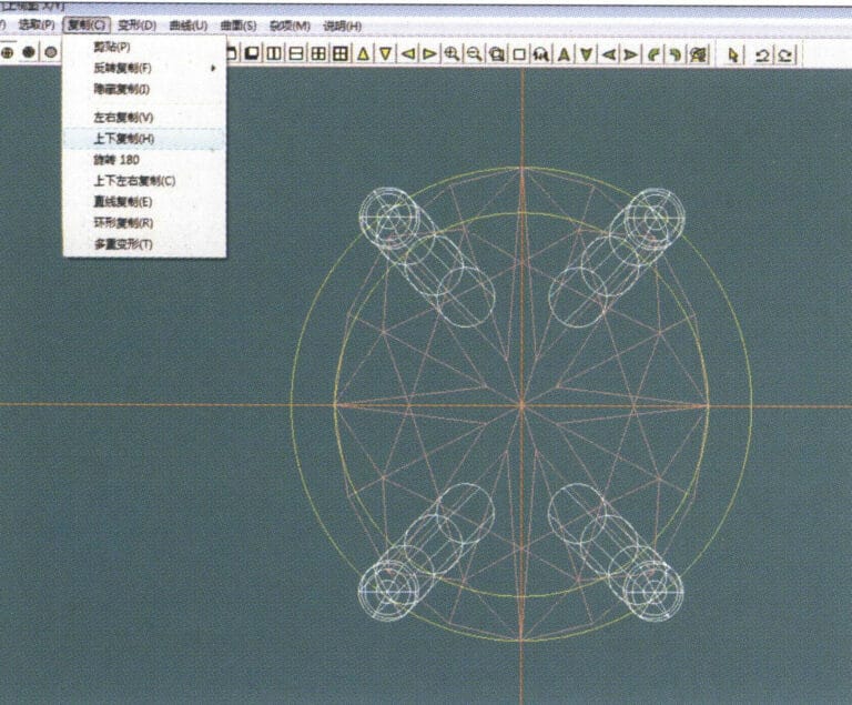
8. Select "Copy" > "Copy Left and Right" from the menu bar to copy the claw shape

9. Select "Copy" > "Copy Up and Down" from the menu bar to copy the claw shape again
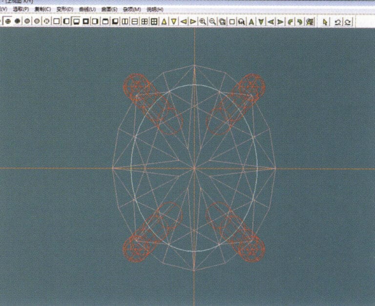
9. Select "Copy" > "Copy Up and Down" from the menu bar to copy the claw shape again

10. Select "Deformation" > "Size" from the menu bar to change the circular guideline to an elliptical guideline
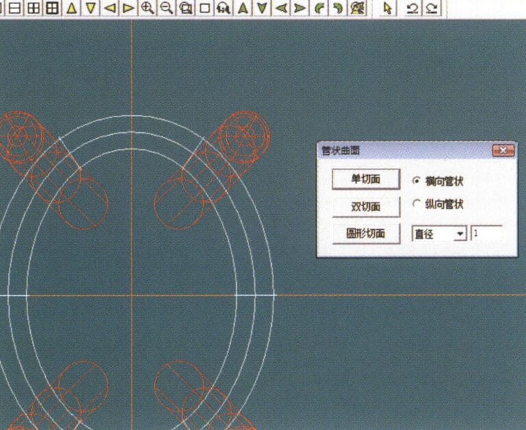
10. Select "Deformation" > "Size" from the menu bar to change the circular guideline to an elliptical guideline

11. Select "Curved Surface" > "Tubular Surface" from the menu bar, enter the relevant values in the "Tubular Surface" dialog box and confirm
11. Select "Curved Surface" > "Tubular Surface" from the menu bar, enter the relevant values in the "Tubular Surface" dialog box and confirm

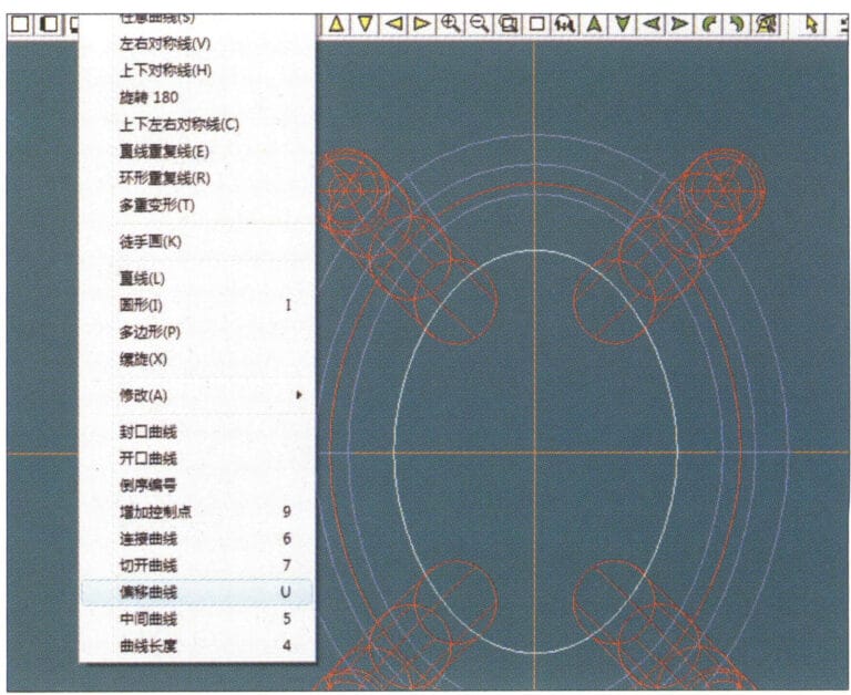
12. Select "Curve" > "Offset Curve" from the menu bar
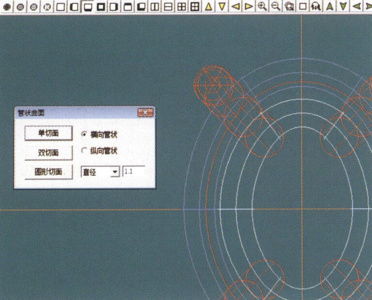
12. Select "Curve" > "Offset Curve" from the menu bar

13. Select "Surface" > "Tubular Surface" from the menu bar, enter the relevant values and confirm
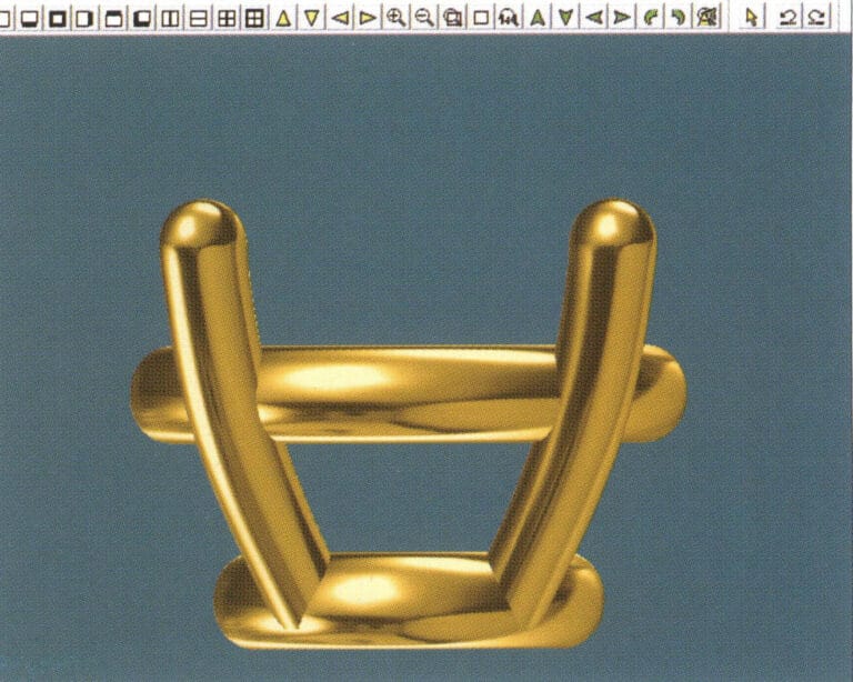
13. Select "Surface" > "Tubular Surface" from the menu bar, enter the relevant values and confirm

14. Select "View" > "Shadow Map" from the menu bar to examine the shadow effects and inspect the setting
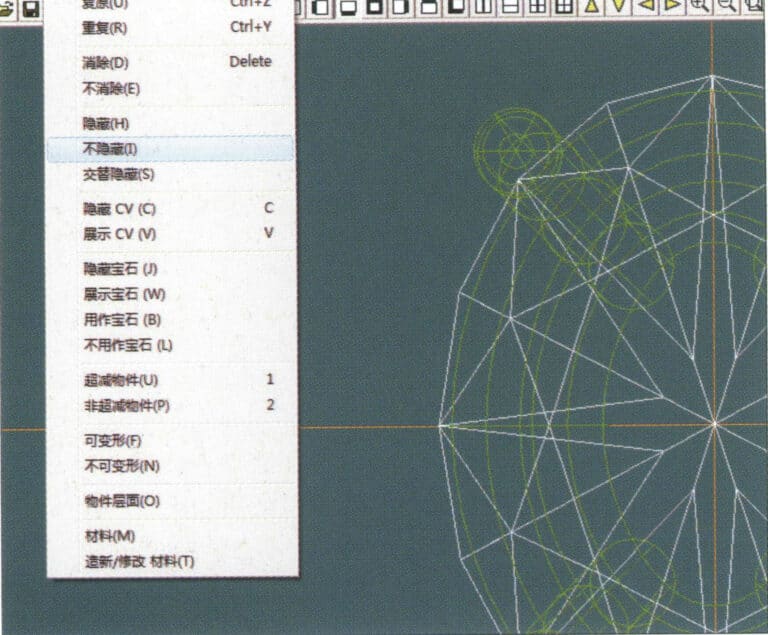
14. Select "View" > "Shadow Map" from the menu bar to examine the shadow effects and inspect the setting

15. Select "Edit" > "Unhide" from the menu bar to display the hidden gems
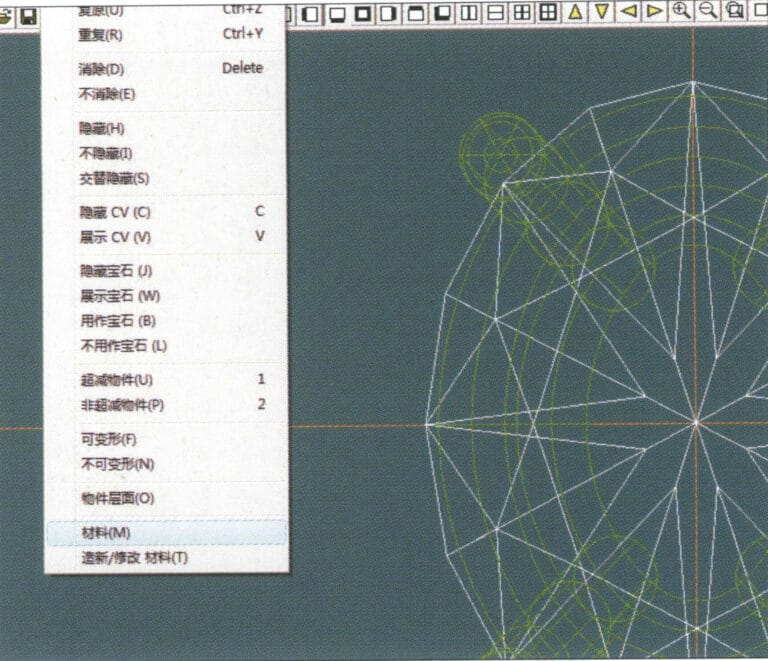
15. Select "Edit" > "Unhide" from the menu bar to display the hidden gems

16. Select "Edit" > "Materials" from the menu bar
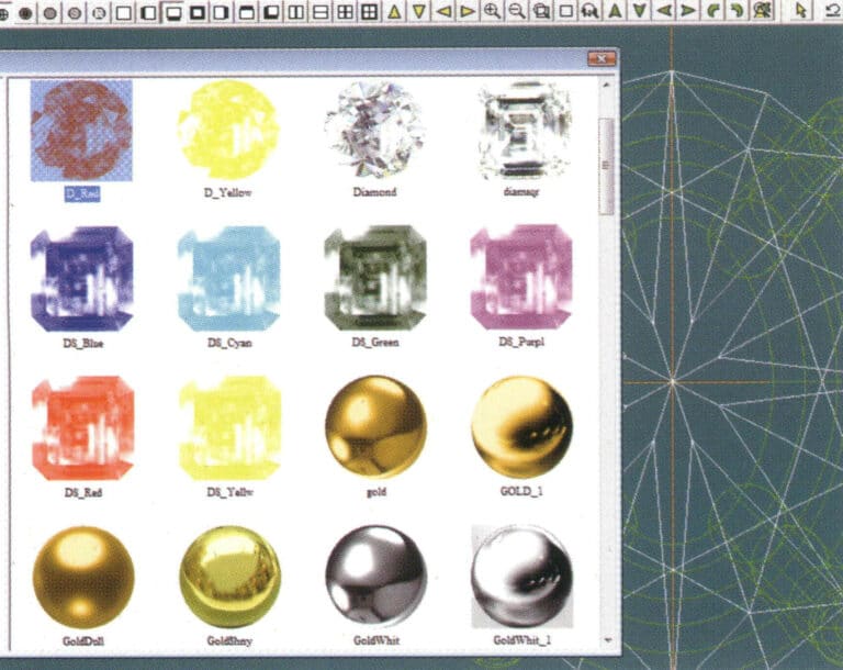
16. Select "Edit" > "Materials" from the menu bar

17. Enter the "Materials" dialog box, select ruby, and confirm
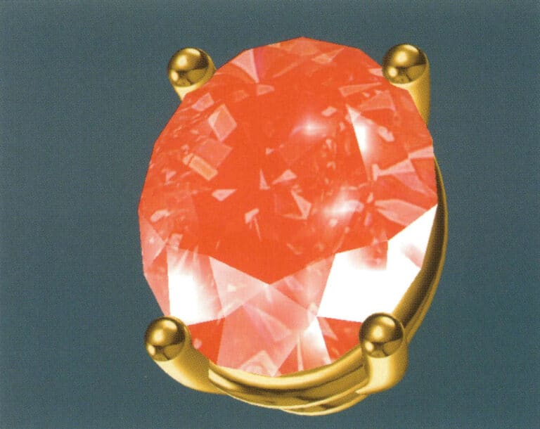
17. Enter the "Materials" dialog box, select ruby, and confirm

18. Select "View" > "Shadow Map" from the menu bar to examine the shadow effects
18. Select "View" > "Shadow Map" from the menu bar to examine the shadow effects

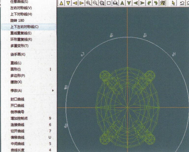
19. Select "Curve" > "Vertical and Horizontal Symmetry Line" from the menu bar as the auxiliary line for the outer circle
19. Select "Curve" > "Vertical and Horizontal Symmetry Line" from the menu bar as the auxiliary line for the outer circle

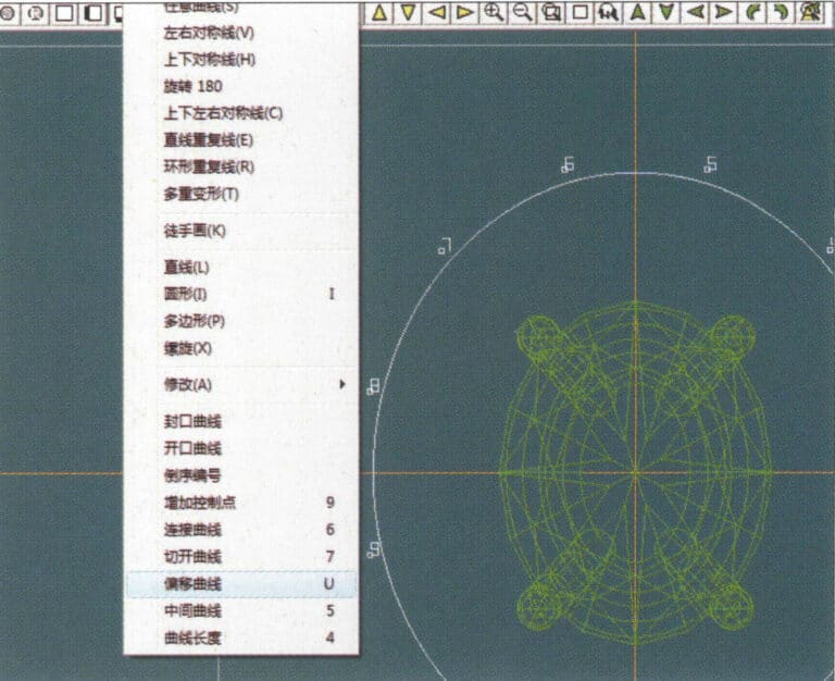
20. Select "Curve" > "Offset Curve" from the menu bar

20. Select "Curve" > "Offset Curve" from the menu bar

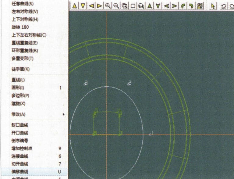
21. Intrați în caseta de dialog "Offset Curve", introduceți valorile relevante ca linii auxiliare pentru cercul interior și confirmați
21. Intrați în caseta de dialog "Offset Curve", introduceți valorile relevante ca linii auxiliare pentru cercul interior și confirmați

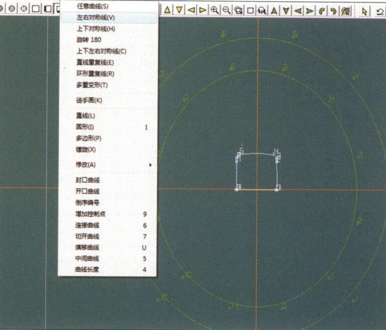
22. Select "Curve" > "Left-Right Symmetrical Line" from the menu bar as the cross-section of the coil
22. Select "Curve" > "Left-Right Symmetrical Line" from the menu bar as the cross-section of the coil

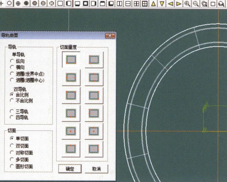
23. Select "Curved Surface" > "Rail Surface" from the menu bar to enter the "Rail Surface" dialog box, select the relevant options and confirm
23. Select "Curved Surface" > "Rail Surface" from the menu bar to enter the "Rail Surface" dialog box, select the relevant options and confirm

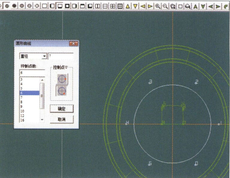
24. Select "Curve" > "Circular Curve" from the menu bar, enter the relevant values in the "Circular Curve" dialog box, and confirm; left-click on one curve as the left guide curve, click on another curve as the right guide rail, and then select the coil cross-section as the cross-section of the guide rail surface; once completed, it serves as the auxiliary line for the outer circle of the chain threading position
24. Select "Curve" > "Circular Curve" from the menu bar, enter the relevant values in the "Circular Curve" dialog box, and confirm; left-click on one curve as the left guide curve, click on another curve as the right guide rail, and then select the coil cross-section as the cross-section of the guide rail surface; once completed, it serves as the auxiliary line for the outer circle of the chain threading position

25. After completing the outer auxiliary lines for the chain position, select "Curve" > "Offset Curve" from the menu bar
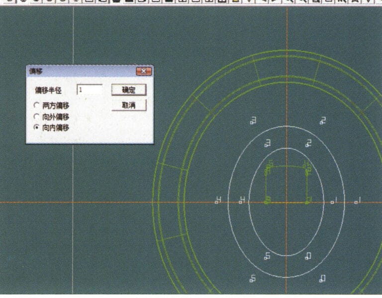
25. After completing the outer auxiliary lines for the chain position, select "Curve" > "Offset Curve" from the menu bar

26. Enter the "Offset Curve" dialog box, input the relevant values, and confirm
26. Enter the "Offset Curve" dialog box, input the relevant values, and confirm

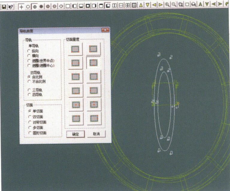
27. Select "Surface" > "Rail Surface" from the menu bar to enter the "Rail Surface" dialog box, select the relevant options and confirm, left-click on a curve to set it as the left rail curve, click on another curve to set it as the right rail, and then select the coil cross-section as the cross-section of the rail surface
27. Select "Surface" > "Rail Surface" from the menu bar to enter the "Rail Surface" dialog box, select the relevant options and confirm, left-click on a curve to set it as the left rail curve, click on another curve to set it as the right rail, and then select the coil cross-section as the cross-section of the rail surface

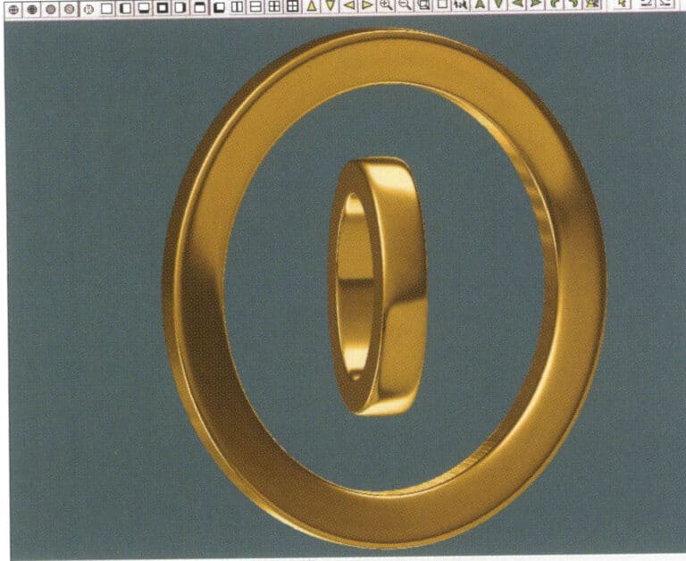
28. Select "View" > "Shadow Map" from the menu bar to inspect the shadow effects
28. Select "View" > "Shadow Map" from the menu bar to inspect the shadow effects

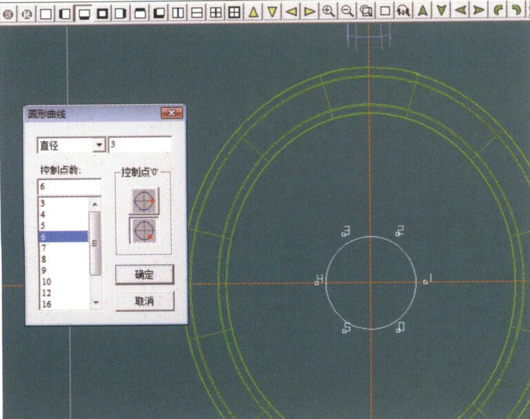
29. Select "Curve" > "Circular Curve" from the menu bar, enter the relevant values and confirm
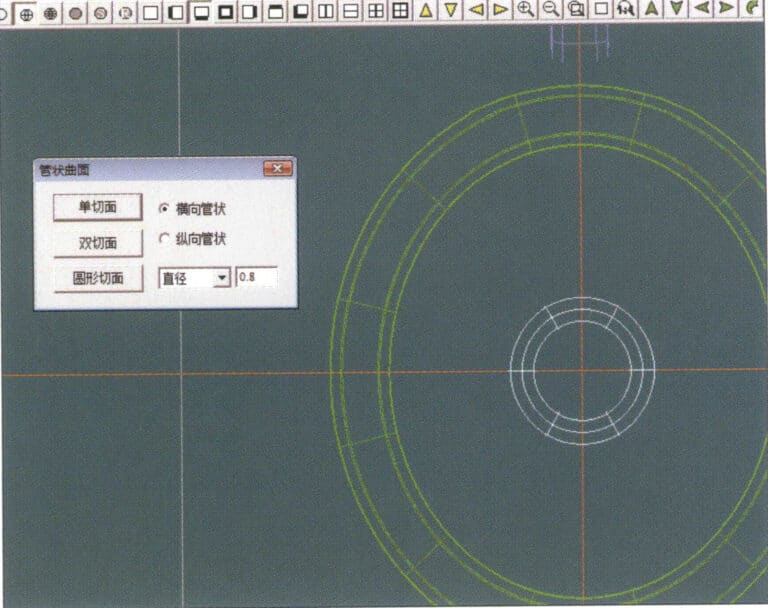
29. Select "Curve" > "Circular Curve" from the menu bar, enter the relevant values and confirm

30. Select "Curved Surface" > "Tubular Surface" from the menu bar, enter the relevant values and confirm
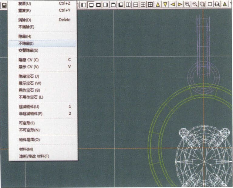
30. Select "Curved Surface" > "Tubular Surface" from the menu bar, enter the relevant values and confirm

31. Select "Edit" > "Unhide" from the menu bar to display the hidden objects
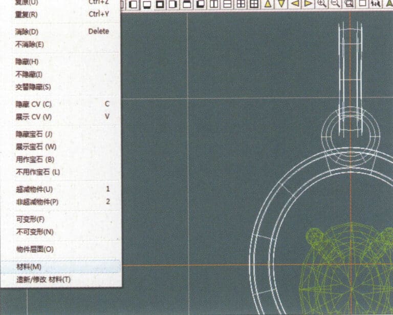
31. Select "Edit" > "Unhide" from the menu bar to display the hidden objects

32. Select "Edit" > "Materials" from the menu bar
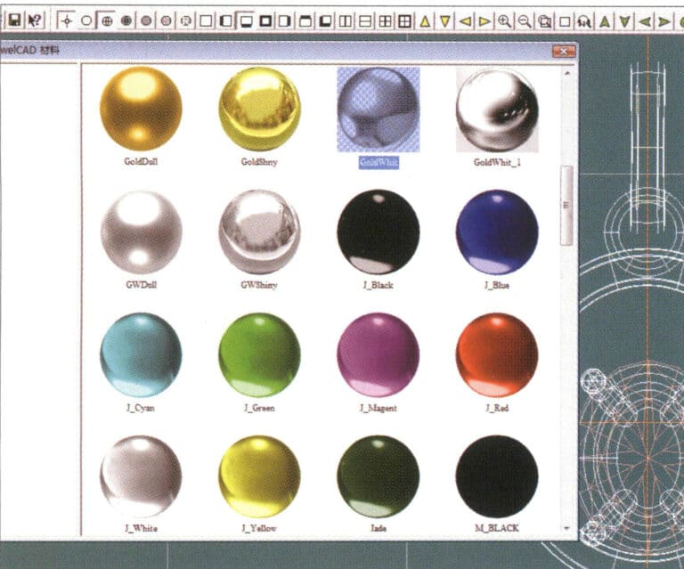
32. Select "Edit" > "Materials" from the menu bar

33. Enter the "Materials" dialog box, select the relevant materials and confirm
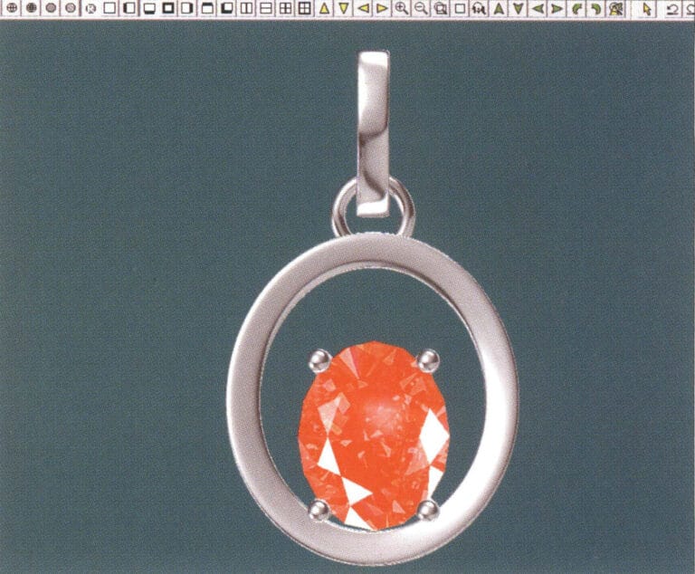
33. Enter the "Materials" dialog box, select the relevant materials and confirm

34. Select "View" > "Shadow Map" from the menu bar to inspect the shadow effects
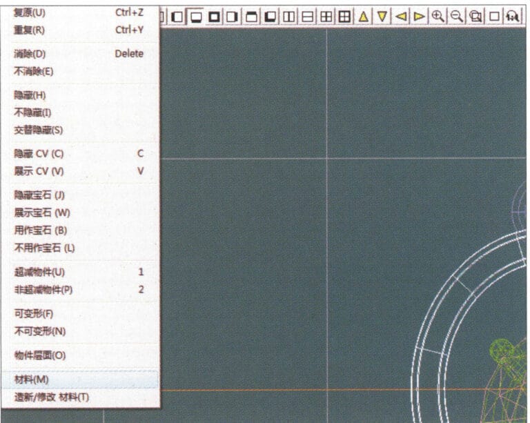
34. Select "View" > "Shadow Map" from the menu bar to inspect the shadow effects

35. Select "Edit" > "Materials" from the menu bar
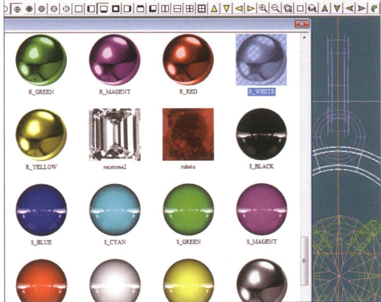
35. Select "Edit" > "Materials" from the menu bar

36. Enter the "Materials" dialog box, select the relevant texture materials and confirm
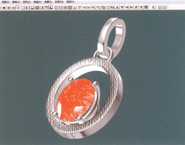
36. Enter the "Materials" dialog box, select the relevant texture materials and confirm

37. Select "View" > "Shadow Map" from the menu bar to inspect the shadow effects 38. Select "File" > "Save As" from the menu bar to save the file

37. Select "View" > "Shadow Map" from the menu bar to inspect the shadow effects

38. Select "File" > "Save As" from the menu bar to save the file

Imaginea lui Heman
Heman

Expert în produse de bijuterii --- 12 ani de experiență abundentă

Bună, dragă,

Sunt Heman, tată și erou a doi copii minunați. Sunt bucuros să împărtășesc experiențele mele în domeniul bijuteriilor în calitate de expert în produse de bijuterii. Din 2010, am servit 29 de clienți din întreaga lume, cum ar fi Hiphopbling și Silverplanet, asistându-i și sprijinindu-i în designul creativ de bijuterii, dezvoltarea și fabricarea produselor de bijuterii.

Dacă aveți întrebări despre produsul de bijuterii, nu ezitați să mă sunați sau să îmi trimiteți un e-mail și să discutăm o soluție adecvată pentru dvs. și veți primi mostre gratuite de bijuterii pentru a verifica detaliile de calitate ale meșteșugului și bijuteriilor.

Să creștem împreună!

Lasă un răspuns

Adresa ta de email nu va fi publicată. Câmpurile obligatorii sunt marcate cu *

Categorii POSTS

Aveți nevoie de sprijin pentru producția de bijuterii?

Trimiteți solicitarea dvs. către Sobling
202407 heman - Expert în produse de bijuterii
Heman

Expert în produse de bijuterii

Bună, dragă,

Sunt Heman, tată și erou a doi copii minunați. Sunt bucuros să împărtășesc experiențele mele în domeniul bijuteriilor în calitate de expert în produse de bijuterii. Din 2010, am servit 29 de clienți din întreaga lume, cum ar fi Hiphopbling și Silverplanet, asistându-i și sprijinindu-i în designul creativ de bijuterii, dezvoltarea și fabricarea produselor de bijuterii.

Dacă aveți întrebări despre produsul de bijuterii, nu ezitați să mă sunați sau să îmi trimiteți un e-mail și să discutăm o soluție adecvată pentru dvs. și veți primi mostre gratuite de bijuterii pentru a verifica detaliile de calitate ale meșteșugului și bijuteriilor.

Să creștem împreună!

Urmați-mă

De ce să alegeți Sobling?

Sobling Team Members producător de bijuterii de argint și fabrică
CERTIFICĂRI

Sobling respectă standardele de calitate

Sobling respectă certificatele de calitate ca TUV CNAS CTC

Cele mai noi mesaje

Figura 2-27 Poziția de utilizare a unei dălți cu cap plat

Cum se face setarea Bezel? Concentrarea pe tehnicile de utilizare a pietrelor cabochon și fațetate

Învățați elementele de bază ale montării în bezel pentru bijuterii, ușor pentru începători. Acoperă pietre cabochon ovale și în formă de picătură, plus pietre fațetate. Obțineți sfaturi privind pregătirea, îndoirea, tăierea și montarea metalului. Esențial pentru bijutieri, studiouri și designeri care realizează piese personalizate.

Citește mai mult "
Piatră prețioasă

Secretele a 14 tipuri de pietre prețioase: Ghidul dvs. pentru kyanite, cordierite și multe altele

Explorați o varietate de pietre prețioase mai puțin cunoscute, dar captivante. Aflați ce le face unice pe fiecare, de la nuanțele asemănătoare safirului ale kyanitei la Sugilita mistică și modelele vibrante ale malachitei. Perfect pentru creatorii și colecționarii de bijuterii care caută pietre distinctive pentru creațiile lor.

Citește mai mult "
instrumente și tehnici de proiectare a bijuteriilor

Cum să stăpânești designul bijuteriilor: Instrumente, tehnici și sfaturi pentru creații uimitoare

Acest ghid este perfect pentru magazinele de bijuterii, studiouri și designeri. Acesta acoperă instrumente esențiale precum creioanele, guma de șters și șabloanele și vă învață cum să desenați bijuterii folosind perspective diferite. Învață să exprimi culori și materiale precum aurul, pietrele prețioase și perlele. Excelent pentru comercianții cu amănuntul, vânzătorii de comerț electronic și celebritățile care caută piese personalizate.

Citește mai mult "
Figura 6-23 Opal vopsit

Ghidul final al pietrelor de jad optimizate pentru bijutieri. 8 tratamente comune de optimizare și metode de identificare pentru pietrele de jad

Descoperiți adevărul din spatele frumuseții jadului cu ajutorul ghidului nostru. Aflați cum diferă jadul de clasa A, B și C, identificați pietrele prețioase vopsite și umplute și asigurați-vă că aveți în stoc doar cele mai bune și mai autentice pietre. O lectură esențială pentru bijutieri, designeri și comercianți cu amănuntul care doresc să își îmbunătățească meseria.

Citește mai mult "
Figura 5-10 Vedere din față a cabinetului independent (unitate: mm)

Cum să stăpânești designul de prezentare a bijuteriilor: Tehnici, pași și exemple din viața reală

Învățați cum să proiectați exponate uimitoare pentru bijuterii! Acest ghid vă învață cum să planificați și să creați aranjamente atrăgătoare pentru magazinul sau atelierul dumneavoastră. Obțineți sfaturi privind utilizarea materialelor, iluminatului și culorilor potrivite pentru a vă face bijuteriile să strălucească. Vedeți exemple reale de la branduri de top precum Justgold și Diamond Family. Perfect pentru magazinele de bijuterii, designeri și vânzători online.

Citește mai mult "
Figura 5-8-2 Chihlimbar roșu sânge impregnat cu ulei

Ce este piatra prețioasă chihlimbar? O călătorie prin istorie, știință și estetică

Descoperiți istoria antică a chihlimbarului în comerț și religie. Aflați cum să vă îngrijiți chihlimbarul și să-i autentificați calitatea. Acest ghid este perfect pentru magazinele de bijuterii, studiouri, mărci, comercianți cu amănuntul, designeri, vânzători de comerț electronic și pentru cei care creează piese personalizate celebre.

Citește mai mult "

10% Off !!

Pe toate fiecare primul ordin

Abonați-vă la newsletter-ul nostru

Abonați-vă pentru a primi cele mai recente actualizări și oferte!

Sobling producător de bijuterii obține o cotație pentru bijuterii dvs.
Ghidul final de aprovizionare - 10 sfaturi pentru a economisi milioane pentru aprovizionarea de la noi furnizori
Descărcare gratuită

Ghidul final de aprovizionare a întreprinderilor

10 sfaturi valoroase vă pot salva milioane de euro pentru bijuteriile dvs. Sourcing de la furnizori noi
Sobling producător de bijuterii personalizare gratuită pentru modelele dvs. de bijuterii

Fabrica de bijuterii, personalizarea bijuteriilor, fabrica de bijuterii Moissanite, bijuterii din cupru alamă, bijuterii semiprețioase, bijuterii cu pietre sintetice, bijuterii cu perle de apă dulce, bijuterii din argint Sterling CZ, personalizarea pietrelor semiprețioase, bijuterii cu pietre sintetice