How to Make Jewelry Wax Model and Master Models for Jewelry Casting?
The fundamental principles and operational skills for 5 typical tasks
In jewelry production, lost-wax casting is the main forming process. Original model production is the first step in the casting process, which has a significant impacts casting quality, production efficiency, and other aspects. The traditional method of original model production mainly involves hand-carving wax models. Hand-carved wax models are a modeling technique that integrates both additive and subtractive methods. By referring to the jewelry design drawings, wax is used as the material, and carving tools are the medium to sculpt the wax into a wax template corresponding to the design drawings. This technique allows for the free shaping of the original model. However, due to its reliance on manual labor, production efficiency is low, and the stability of product quality is difficult to guarantee. With the development of technology, original model production mainly relies on 3D printing forming technology. 3D printing, academically known as additive manufacturing, refers to creating three-dimensional models by slicing the model and stacking it layer by layer with equipment, ultimately producing a three-dimensional entity model that is completely consistent with the corresponding data model. The application of 3D printing technology has significantly improved production efficiency and ensured the accuracy of product dimensions. Depending on the form of raw materials, the methods of layer-by-layer stacking in 3D printing also vary, including uv-cured modeling, fused deposition modeling, and selective laser sintering. UV-Cured modeling and fused deposition modeling are jewelry’s most commonly used methods for original model production.
After the original model is completed, a sprue must be set. The sprue is the reserved channel for the flow of molten metal during the casting process, and it is also the channel for compensating the shrinkage of the metal during the solidification of the casting. The correct setting of the sprue is a basic condition for ensuring casting quality, and many defects in lost wax unreasonable sprue settings directly or indirectly cause casting. When setting the sprue, it is necessary to follow some basic principles while also considering the jewelry product’s structure, material, size, and other characteristics.

Completed ring blank
Πίνακας περιεχομένων
Section I Hand-carved Wax Model Production
1. Γνώσεις υποβάθρου
1.1 Properties of Wax Materials
Wax is the basic material for making jewelry original models. Various types of wax are used in the jewelry industry, but only a few have the right balance of strength and toughness suitable for carving wax models. Most waxes are either too brittle or too soft, making them difficult to carve using conventional methods. The suitability of wax for carving models is mainly evaluated from five aspects: hardness, strength, toughness, uniformity, and melting point.
The wax used for carving models should have sufficient hardness so that the surface is not easily damaged when subjected to force, allowing for the carving of fine patterns.
Since the wall thickness of jewelry is generally small, with some pieces having a wall thickness of less than 0.3 mm, it is required that the carving wax has sufficient strength and toughness so that the thin wax material does not deform or break.
The wax material should also have a uniform density. To ensure that the patterns on the wax model have the same clarity, the wall thickness of the wax must be consistent. When the density of the wax material is uniform, the method for judging wall thickness is usually quite simple: look at the color of the wax model in various places against the light; if the wall thickness is inconsistent, the colors will differ. However, when the density of the wax material is uneven, even if the wall thickness is the same, it may present different colors, which could lead to misjudgment during operation.
For wax models directly used for lost-wax casting, the wax material is also required to easily melt away during the roasting process, have a small thermal expansion coefficient, and leave minimal residue after roasting.
Well-known carving wax brands in the industry include Ferris, Matt, and Kerr and so on.
1.2 Classification of Wax Materials
According to different performance and processing characteristics, carving wax can be classified in various ways.
(1) Classification by Hardness
According to hardness, carving wax can be divided into three categories: high hardness wax, medium hardness wax, and soft wax. For ease of distinction, the industry uses corresponding colors. Green, purple, and blue are used to represent them. Taking Ferris brand carving wax as an example, the characteristics of green wax, purple wax, and blue wax are as follows.
Green wax: This wax has the highest hardness and the lowest elasticity and softness. Green wax is the most widely used carving wax, suitable for carving sharp angles and intricate details in wax models. It can be processed to a thickness of less than 0.2 mm, maintaining its shape well without easily deforming, and polished to a smoothness like glass. The low toughness of green wax makes it prone to cracking when carving large and thin curved surfaces. The melting temperature of green wax is 110℃, and when it melts, it can immediately turn into liquid without going through a dense stage. Various wax saws, carving knives, wax files, and machine burs can conveniently cut, filing, and process surface textures with green wax.
Purple wax: Purple wax has medium hardness, good elasticity, and softness, making it suitable for making more complex wax models. The melting temperature of purple wax is 107℃, and it becomes softer when heated, becoming noticeably softer as the temperature increases until it turns into liquid, making it unsuitable for creating fine patterns.
Blue wax: Blue wax has the lowest hardness and is very soft, which makes it suitable for making simple wax models, especially for works with spherical or curved surfaces. A 3 mm thick piece of blue wax can be bent into a hemispherical shape after soaking in boiling water. Blue wax is best carved with a knife, as it does not produce wax powder like green wax or make off like purple wax. Blue wax melts at 104℃ but does not turn into a flowing liquid; it maintains a certain viscosity. It is very convenient to use blue wax to replicate the surface patterns of a master model, but it is not suitable for making very fine patterns or processing with a hanging grinder.
(2) Classification Based on Shape and Use
In terms of shape, wax materials can be blocks, sheets, tubes, strips, threads, etc. Various pre-shaped wax materials or wax accessories are available for selection, such as ring wax, bracelet wax, bezel wax, prong wax, and other auxiliary shaping waxes to facilitate production use, save processing time, and reduce wax material loss. The shapes, characteristics, and application ranges of commonly used wax materials for hand-carving are shown in Table 1-1.
Table 1-1 Commonly Used Wax Materials for Hand-carving
| Wax Material Category | Σχήμα | Χαρακτηριστικά | Application Range |
|---|---|---|---|
| Hard Wax (Wax Bricks, Wax Sheets, etc.) |

|
High hardness, excellent processing performance, very suitable for carving | Wax models for carving jewelry, ornaments, and crafts |
| Soft wax |

|
Low hardness, easy to bend and deform, can be freely shaped | Biomimetic accessories with line designs, such as plant leaves, vines, and insect wing textures |
| Ring wax |

|
The design for rings includes pure round and "U" shaped platforms, with both solid and hollow types, saving processing time. | Making men's rings and women's rings |
| Bracelet wax |

|
Can be used for making round, oval, and square bracelets, saving processing time | Making bracelets |
| Setting wax |

|
Standard shape, size and high strength, not easy to break | Wax model for making standard gemstone’s bezel |
| Prong wax |

|
Complete sizes, good elasticity, can wax be bent, not easy to break | Making prongs and linear modeling wax parts |
1.3 Wax Model Structure Size Terminology
When the model-making personnel receive the order, they must first understand the customer’s requirements based on the order, such as jewelry size, gemstone size, etc. Taking rings as an example, it is necessary to understand the specific meanings of the following terms.
Ring size: The inner diameter of the ring, which can be measured in various standards such as American, Hong Kong, Japanese, and Italian sizes.
Ring bottom width: Commonly referred to in the industry as “ring shank width,” it refers to the width at the very bottom of the ring.
Ring bottom thickness: Commonly referred to as “ring shank thickness” in the industry, it refers to the thickness at the very bottom of the ring.
Ring height: Commonly referred to as “shoulder height” in the industry, it refers to the vertical height of the edge of the ring’s head.
Prong height: Commonly referred to as “side height” in the industry, it refers to the total height of the head, which needs to be measured with a caliper.
Plain shank: Refers to the area between the ring shank and the head, which is the remaining part after removing the pave setting stones or other patterns.
Plain shank thickness: Refers to the thickness of the areas on both sides of the head without pave setting positions, measured with internal calipers. If the customer has no special requirements, it is usually taken as 0.6~0.7 mm.
Pave setting position thickness: Refers to the thickness of the pave setting position, which needs to be measured with an internal caliper. If the customer has no special requirements, it can be taken as 1~1.2 mm.
Stone setting mount edge thickness: Refers to the thickness around the head setting mount, which can be taken as 1.1~1.3 mm.
The specific locations of the above terms are shown in Figure 1- 1.

Size of the gemstone: Refers to the dimensions of the gemstone. If the order includes a gemstone, the setting position can be opened according to the actual size; if the order does not include a stone, the size range of the gemstone must be determined based on the gemstone information code in the order. The cutting styles of gemstones generally include round brilliant cur, baguette cut and princess cut, etc.
1.4 Coefficient of Thermal Expansion
2. Υλοποίηση εργασιών
This task takes the pure gold ring wax model as an example, mainly using shallow relief craftsmanship to complete the hand-carved wax model production.
(1) Cutting Material according to the Order
According to the specifications and dimensions of the pattern, use a caliper to measure the dimensions and draw lines, and use a hacksaw to cut the required wax block, as shown in Figure 1-2.
(2) Rough Shaping
Place the cut wax block on a square file to smooth it out, creating three right-angled surfaces, namely the front view and top view at right angles, the front view and side view (left or right) at right angles, and the top view and side view at right angles, as shown in Figure 1-3. After polishing the three right angles, use a caliper to draw the baseline that intersects at the center and is perpendicular along the right angle edges (including the top and back, referred to as the center vertical line) and the contour line of the mounting as shown in Figure 1-4. Use a compass with the intersection of the contour line of the mounting and the center vertical line as the starting point, with half a ring size as the radius, to take points on the center vertical line and use this as the center to draw the inner circular curve of the ring (including the back), as shown in Figure 1-5.

Figure 1-2 Sawing Wax

Figure 1-3 Filing the Wax Block

Figure 1-4 Drawing the Baseline

Εικόνα 1-5 Σχεδίαση της γραμμής τόξου
Then drill a small hole on the inner side of the arc, pass the saw blade through, and use a saw frame to cut out a ring-sized hole along the arc line, as shown in figure 1-6.
Use a wax machine bur to trim the inner circular edge, and then use a wax ring carving knife to scrape the inner circle diameter to the ring-sized scale reading position, ensuring that the bottom and top surfaces of the ring-sized hole are the same size as shown in Figure 1-7.

Figure 1-6 Sawing the ring-sized hole

Figure 1-7 Scraping the ring size
(3) Fine Detailing
After completing the overall shape, proceed to the next step of detail repair. Use a wax machine bur to shape the outer form of the ring, use a square file to make the left and right edges symmetrical, and smooth the bottom edge, as shown in Figure 1-8. Use a caliper to draw the centerline on the side, set the width of the mounting and bottom edge, and use a wax machine bur to shape both edges. If the men’s ring has double-slanted straight edges, place it on the square file to grind it into a diagonal symmetrical shape. Be careful to maintain the overall shape of the ring, and use a small wax file to refine it, ensuring all four sides are neat and symmetrical. Use a pointed bur to draw the pattern (letters, shapes, or designs) on the mounting (ring surface), and use a diagonal knife or medium-sized crescent knife to carve the inner border line, outer border line, or engrave letters in sequence, as shown in Figure 1-9. Use a side knife to hollow out the gaps between the frame and the letters (or shapes), and then use a flat-bottom knife to finish.

Figure 1-8 Shaping the Appearance

Figure 1-9 Carving Patterns
Observe the ring face from a distance, use a knife to correct the characters and shapes, and refine carefully to ensure the casting has clear layers and a lively image with smooth curves and flowing lines.
(4) Remove bottom weight
After confirming that the overall ring is accurate, use a coarse wave bur to hollow out the wax inside the ring, as shown in Figure 1-10. Leave a 1 mm wall thickness with the remaining surface thickness of 0.5~0.8 mm. Note that the wall thickness should be uniform, avoiding being too thin and causing perforation or too thick and adding weight.
(5) Trimming
Use a carving knife to scrape off surface scratches, use 400#~600# coarse sandpaper for rough polishing, and then use 800#~1200# fine sandpaper for fine sanding, as shown in Figure 1-11. Wipe the castings with lacquer thinner or white oil.

Figure 1-10 Bottom Dredging

Figure 1-11 Polishing with Sandpaper
Section II Production of Light-Cured Original Model
1. Γνώσεις υποβάθρου
1.1 Principles of Rapid Prototyping Technology
Rapid prototyping technology, or rapid prototype manufacturing technology, is an important part of modern advanced manufacturing technology. Rapid prototyping equipment can directly, quickly, and accurately transform design concepts or design plans into actual part prototypes or directly manufacture parts through processes such as model establishment, approximation processing, and slicing processing, providing an efficient and low-cost means for prototype production and verification of design concepts, thus compensating for the shortcomings of traditional manufacturing methods.
Rapid prototyping is a new manufacturing technology developed based on computer-aided design, computer-aided manufacturing, computer numerical control, laser technology, and new materials. It is based on the principles of discretization and stacking, allowing the CAD model of a part to be discretized in a certain way into processable discrete surfaces, discrete lines, and discrete points. Then, through physical or chemical means, these discrete surfaces, lines, and points are stacked to form the overall shape of the part. The specific method involves converting the three-dimensional CAD model of the part into a diffrent format and slicing it into layers to obtain the two-dimensional contour shapes of each layer’s cross-section. According to these contour shapes, a laser beam selectively solidifies layers of liquid photosensitive resin, cuts layers of paper or metal sheets or sinters layers of powdered materials, and selectively sprays layers of adhesive or thermoplastic materials using a jet source, forming the planar contour shapes of each cross-section, which are then gradually stacked to create a three-dimensional part. Rapid prototyping technology does not use traditional “subtractive” processing methods (removing excess material from the workpiece with tools to obtain the desired part shape). Instead, it employs a new “additive” processing method, which first creates a thin layer of rough material using points, lines, or surfaces. It then gradually stacks multiple layers of rough material to form complex-shaped parts. The basic principle of rapid prototyping technology is to decompose complex three-dimensional processing into the stacking of simple two-dimensional processing. Hence, it is also referred to as “layered manufacturing,” “additive manufacturing,” or “incremental manufacturing.”
1.2 Model Slicing
1.3 Advantages of Rapid Prototyping Technology
In the traditional product sample development process, designers first need to form a three-dimensional image of the user’s requirements in their minds, then convert it into two-dimensional engineering drawings, which later need to be transformed into three-dimensional samples or models by the manufacturers. If modifications to the product are required, converting between three-dimensional and two-dimensional must be repeated multiple times. Therefore, the traditional product sample design and development process adopts a step-by-step approach, often taking a long time and extending the product development cycle.
Rapid prototyping technology integrates the concept of concurrent engineering, solving the problem of quickly and intuitively analyzing and demonstrating products in engineering design. This allows the designed products to be directly generated as three-dimensional solid models without intermediate engineering drawings or steps. It has the following obvious advantages: ① greatly shortens the new product development cycle, allowing products to be brought to market faster; ② significantly reduces the R&D costs of new products; ③ increases the first-time success rate of new product launches; ④ supports the implementation of concurrent engineering; ⑤ supports technological innovation and improves product appearance design.
1.4 Rapid Prototyping Process Methods
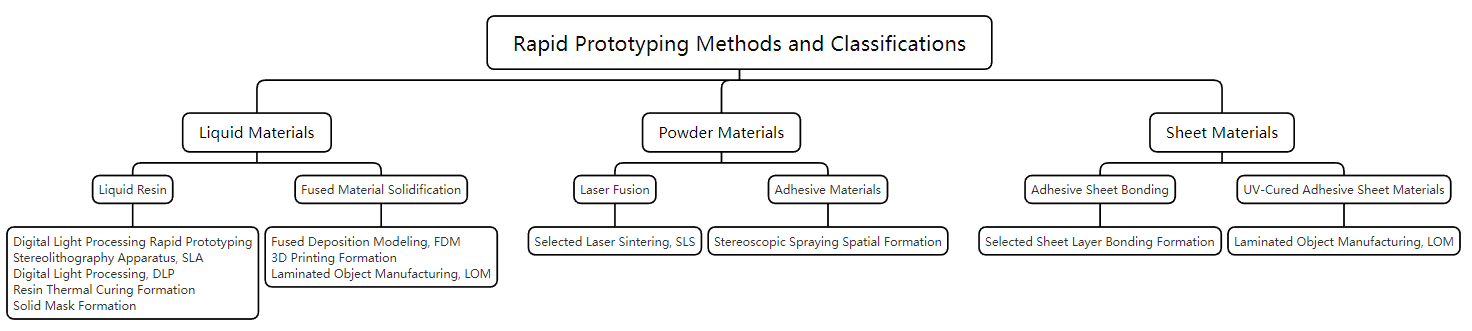
(1) Stereo Lithography Apparatus (SLA)
This molding method uses photosensitive resin as the raw material. Under computer control, a UV laser scans the surface of the liquid photosensitive resin according to the layered cross-sectional data of the part, causing the resin in the scanned area to undergo a photopolymerization reaction and solidify, forming a thin layer of the part; after one layer is cured, the workbench descends, and a new layer of liquid resin is applied on the previously cured resin surface for the next layer of scanning and curing. The newly cured layer firmly bonds to the previous layer and this process is repeated until the entire part prototype is completed, as shown in Figure 1-13.

The SLA method parses the layered cross-sectional data into countless pixel points. The computer controls all pixel points, connecting them into continuous lines and drawing them into surfaces through the parallel arrangement of continuous lines. The laser completes the layered cross-section point-by-point curing along a linear optical path. The main process parameters of the SLA method include laser spot diameter, slice layer thickness, spot step length, spot dwell time, and light travel direction. The surface quality of the printed model is limited not only by the resolution of the hardware but also by the design of the computer’s optical path. The characteristics of this molding method include relatively high equipment costs, longer printing times, and limited laser tube lifespan. It can create parts with complex shapes (hollow parts) and finer details (jewelry and crafts).
(2) Digital Light Processing (DLP)
The principle of digital light processing rapid prototyping technology is to use a DLP projector to project the layered graphics of the model onto the surface of the printing platform beneath the resin tank in a planar manner. The entire surface is cured simultaneously. After one layer of resin is cured, the printing platform rises by one layer height, and then another layer of resin is cured, continuing this process layer by layer until the entire model is printed.
The characteristic of the DLP method is that it achieves simultaneous curing of the entire layered surface through projection, effectively increasing the speed of 3D printing. During the printing process, the model is in an inverted suspended state, with layers being added individually, allowing for printing with a small amount of material. Figure 1-14 shows a typical DLP 3D printer. The main process parameters of the DLP method include single-layer exposure time, forming direction, and slice layer thickness. The smaller the slice layer thickness, the higher the printing precision, but the corresponding printing time will also be extended. The exposure time for each layer affects the actual layer thickness printed, and different types of resin require different exposure times; therefore, single-layer exposure time is an important parameter of the DLP process. The printing process of the DLP method is similar to other 3D printing methods, being a layer-by-layer accumulation process. During the layering and stacking process, the graphics are processed in an approximated shape manner. Thus, the forming method of the model during the printing process also affects the printing precision.

The prominent feature of the DLP method is that the light source has changed from point scanning to area scanning, allowing the printing surface to be formed in one go, greatly saving the time of point-by-point scanning and making the printing process faster and more efficient. Specifically, the DLP method has the following advantages.
① Wide printing area. DLP technology uses a surface light source design, allowing effective expansion of the printing model’s area, enabling a wider range of printable sizes.
② High printing accuracy and low distortion rate. The DLP method has no moving beam, resulting in minimal printing vibration deviation. Additionally, the DLP optical system can be paired with automatic calibration technology, allowing for efficient and high-precision size correction, achieving higher surface resolution and making subsequent processing easier.
③ Fast printing speed. Compared to the transition from point to line to surface in SLA 3D printing technology, the DLP 3D printing technology allows for a one-time forming process, making the printing process faster and more efficient, better meeting the market demand for quantitative and refined production. DLP equipment has no moving nozzles, eliminating material blockage issues, and does not require heating components, enhancing electrical safety.
1.5 Common Tools and Supplies for Stereo Lithography Apparatus
(1) Cleaning cloth: Used to clean the inner surface of the flexible film layer.
(2) Cotton swab: Used to clean the resin box ID chip.
(3) General cleaner (glass cleaner) or detergent: Cleaning the printer’s cover, casing, and display screen.
(4) Isopropyl alcohol with a concentration of 90% or higher: Used to clean the printer’s optical components, build platform, and resin box ID chip, and can also be used to clean the work surface and tools.
(5) Lithium grease for ball bearings: Used to lubricate the X shaft and Z shaft screw.
(6) Low-fiber paper towels: Used for cleaning work surfaces and tools, protecting sensitive components, and can also be used to wipe off residual grease, resin, or solvents.
(7) Wear-resistant microfiber cloth: Used for cleaning the printer’s cover, casing, and display screen.
(8) Chlorinated polyethylene cleaning cloth: Used for cleaning the printer’s optical components and resin cartridge ID chip.
(9) Rubber ball blower: Used to remove dust from optical glass windows.
(10) Resin tank cleaning tool: Used for inspecting and cleaning the inner surface of the flexible film layer.
1.6 Printer Inspection and Maintenance
(1) Checking Before Each Print
The operating environment must be checked, the build platform cleaned, and the fastening valves inspected before each print.
(2) Monthly Inspection
The resin box ID chip should be maintained monthly, the exterior of the resin tank should be checked for cleanliness, and the resin tank frame should be inspected for damage.
(3) Regular Maintenance
Set a fixed period to regularly check the integrity of the machine cover, verify if the display screen and collection device are functioning properly, check for any damage to the outer shell, and ensure the lifting and retracting operations of the axis X and axis Z are stable.
2. Υλοποίηση εργασιών
This task is to create a jewelry prototype using the SLA 3D printer.
(1) Obtaining the Model File
Complete the design of the model and export the model’s STL file.
(2) Model Slicing
After importing the model’s STL file, complete the slicing operation using the slicing software. The specific steps are as follows.
① Opening the Model in PreForm
When opening PreForm, the interface is shown in Figures 1-15. Click “File” – “Open” in the menu bar to display the “Open File” window. Select the file to be printed.

② Preparing the Model in PreForm
Change the view using the function buttons on the left side to view the model structure, as shown in Figure 1-16. Then, select the print layer thickness.

1) Click the “<” button at the top right. The “Task Information” dialog box will open.
2) Click the printer name. The “Task Settings” window will open.
3) Scroll down to the “Select Material” section. Hover the cursor over the desired material to view the available versions of that material type. Click to select the material and version, as shown in Figure 1-17.

4) Scroll to the “Select Print Layer Thickness” section. Click to select the print layer thickness.
5) Click “Apply” for the selected material and print layer thickness settings. The “Task Settings” window will close immediately.
6) Select orientation and support models. Complete the support data. In PreForm, select the model. Click “Support” to open the dialog. Click “Auto-generate All” to add support to all models on the build platform.
(3) Printing Preparation
After setting up the model in PreForm, select a printer to run the print job: choose or manually add a printer in PreForm. Match the consumables (resin tank, resin cartridge) in PreForm to those in the printer. Once completed, send the print job from PreForm to the printer.
① When sending the print job to the printer, click the orange “Print” button. The “Print” window will open, as shown in Figure 1-1

② Click the “Select Device” arrow. The “Device List” window will open, as shown in Figure 1-19.

③ Click the “Select Device” checkbox next to the printer serial name.
④ Click “Select”. The “Print” window opens again. Enter or update the task name.
⑤ Click “Upload Task
(4) Model Printing
After completing the printing preparation, you can proceed to the printing stage.
After uploading the print job to the printer, you can either start the print job directly or access the print job later from the “Queue” (select the model used).
① Click on the print job in the main screen or “queue.”
② Click “Print” to confirm. A new interface will appear.
③ Follow the prompts on the touchscreen to check if the consumables are correctly inserted, then press “Confirm.” Printing will start when the room temperature reaches around 35℃ (95℉).
(5) Post-processing
After printing is complete, the model blank must be removed and post-processed.
① Removing the Model Blank
1) open the printer cover and lift the platform lock after printing.
2) Hold the handle with both hands and remove the build platform from the printer.
3) Close the printer cover. Obtain the model blank from the completed print, as Figure 1-20 shows.

② Cleaning, Air Drying, and Curing the Blank
1) Soak the blank in the specified cleaning agent for half a minute, then gently wipe with a cotton swab to remove the surface resin, as shown in Figure 1-21.

Note: The cleaning agent is a flammable chemical. Keep away from fire sources during operation, including open flames, sparks, and concentrated heat sources.
2) Remove the solvent from the blank.
If the solvent evaporates easily (such as isopropanol), leave it for at least 30 minutes after cleaning to allow the solvent to completely evaporate.
If the solvent does not evaporate easily (such as propylene glycol monomethyl ether), you can wash the blanks with water to remove excess solvent.
3) Allow the blanks to air dry. Before post-curing treatment, ensure all blanks are thoroughly dry, with no excess solvent, resin, or other liquids.
4) Use curing equipment to perform post-curing treatment on the blanks to fully achieve their mechanical properties, as shown in Figure 1-22.

5) A complete model is obtained by removing supports, polishing the surface, and adding coatings for post-processing the blank, as shown in Figure 1-23.

③ Turning off the Printer
After the printing is completed, the device will automatically enter sleep mode. If you need to shut it down, press the power switch next to the power cord at the back of the printer, and the printer will turn on.
Copywrite @ Sobling.Jewelry - Κατασκευαστής προσαρμοσμένων κοσμημάτων, εργοστάσιο κοσμημάτων OEM και ODM
Section III Original Model Production of Fused Deposition Modeling
1. Γνώσεις υποβάθρου
1.1 Fused Deposition Modeling (FDM)

1.2 Types of FDM 3D Printers
The FDM printing process involves aligning the positioning and path of the printing points with those of the extrusion points, transforming digital space into physical objects to obtain physical samples. Based on the mathematical principles of the three-axis point coordinates of the printer X, Y, Z, the architecture of FDM 3D printers can be divided into Cartesian coordinate system architecture, polar coordinate system architecture, spherical coordinate system architecture, etc. Due to the complexity of mathematical operations in applying polar and spherical coordinate system principles in the motherboard firmware and slicing software, 3D printers based on such mathematical principles have a smaller circulation range in the market. Currently, the mainstream FDM 3D printers still adopt Cartesian coordinate system architecture.
Corresponding to the above three architectures, there are three typical 3D printers.
(1) Cartesian Coordinate System Type 3D Printer
The Cartesian coordinate system type typically represents the Cartesian coordinate system architecture. It features a square design, where the base moves along the axis Z while the extruder moves along the axes X and Y, with the three-axis drive operating independently. A typical Cartesian coordinate system type 3D printer is shown in Figure 1-25. The open-source RepRap series, Ultimaker, Printrbot, and the previously open-source Makebot series machines all adopt this Cartesian coordinate system structure. Major manufacturers produce representative models with this structure, which offers moderate printing quality and high stability. An outer frame can also ensure the working area’s temperature, humidity, and other forming conditions. Advantages: simple design, easy maintenance, and precise printing details. Limitations: slower printing speed, the biggest limitation of 3D printers using Cartesian coordinate system architecture.

(2) Core XY Structure 3D Printer
The Core XY structure is a typical representative of polar coordinate architecture, using X and Y dual-axis interactive compound motion. Except for the Z-axis, which uses a single motor drive, the X and Y axis uses two motor systems that alternate through a synchronous belt to achieve displacement. In a Core XY structured 3D printer, the two conveyor belts appear to intersect, but they are actually on two planes, one above the other, as shown in Figure 1-26. This type of printer has a faster printing speed and higher stability during operation. Still, due to its overly complex assembly method and high transmission requirements, it poses higher demands on users, resulting in poor equipment promotion.
(3) Delta 3D Printer
The delta type, or triangular or Deltal type, is typical of spherical coordinate architecture, featuring a circular base with the extruder suspended at the top. The nozzle is supported by three metal arms forming a triangle, as Figure 1-27 shows. The uniqueness of the Delta 3D printer lies in the fact that its base never moves, giving it certain advantages when creating certain types of objects. Advantages: It has a faster printing speed than most other 3D printers, a novel design, and a fixed base. Limitations: Due to the control of the nozzle system through six linkage rods, the three axial transmission components are too concentrated, leading to insufficient stability during operation and relatively low positioning accuracy in the X, Y, and Z axial directions.


1.3 Jewelry FDM 3D printer

The jewelry FDM 3D printer has the following features.
(1) Single nozzle, multi-nozzle design, the main material 100% uses wax, which can be directly used for casting.
(2) Wax coating can achieve sharp model edges, clear features, and smooth surfaces, allowing for a more realistic restoration of the design model. However, because the model is formed by the solidification of molten material, which has fluidity, a dimensional deviation exists between the solidified model and the actual object, which affects printing accuracy.
(3) In the process of fused deposition modeling, in addition to the main product needing to use purple wax, the support material is a low-cost, water-soluble wax, and the entire printing process generates almost no waste, resulting in a very high utilization rate of raw materials.
1.4 Comparison of FDM Technology and DLP Technology
Table 1-6 Comparison of Main Technical Parameters of FDM and DLP
| Technical Indicators | FDM | DLP |
|---|---|---|
| Forming Principle | Layer-by-layer melting forming | Light curing layer-by-layer forming |
| Typical equipment | ProJet MJP 2500W Plus | Envision One |
| The main material of the product | Purple Wax | Photosensitive Resin |
| Supported Material | Water-Soluble Wax | Photosensitive Resin |
| Modeling Size (Typical Model)/mm | 295 X 211 X 144 | 90 X 96 X 104 |
| Operating Temperature Range/℃ | 18 〜 28 | 18 〜 28 |
| Supported File Types | STL、CTL、OBJ、PLY、 XRP、ABD、3DS, etc. | STL or OBJ |
2. Υλοποίηση εργασιών
This task uses the FDM method to print the original model of the ring.
(1) Obtaining the Model File
Complete the model design, as shown in Figure 1-29, and export the model’s STL file.
(2) Printing Preparation
Execute the jet inspection program to confirm that all nozzles are functioning properly. When sending the print job, ensure a clean print bed is installed, and the waste bag is leveled.
① Checking the Platform
Select “Access Platform” from the printer control interface and raise the platform as shown in Figure 1-30. Check the platform to ensure it is clean and defects-free, reinstall the platform back into the printer, and close the top cover.


② Checking the Waste Bag
Select materials, check the percentage of materials in the waste bag and ensure there is enough space in the waste bag to collect the waste generated during printing.
③ Checking/Adding Materials in the Print Cartridge
Check materials through the materials tab to ensure the printing requirements are met.
(3) Printing the Model
Once the preparation is complete, you can proceed to the printing stage with the following specific steps.
① Importing Model File
Double-click the 3D Sprint software to open it, as shown in Figure 1-31. Import the model file.

② Selecting Printer
Click the “Printer” button at the top left to display the list of available printers, select the printer to use for printing, as shown in Figure 1-32, and select ProJet MJP 2500W.

③ Selecting Printing Materials
Select the materials needed for printing the parts, and double-click the materials. The available printing modes will be auto-filled; select “HD Mode.”
④ Sending Print File
In the print selection card, import the STL model file shown in Figure 1-33, open it, select “Auto Arrange,” and click settings to automatically arrange the file on the platform. Then select add to the print job queue, as shown in Figure 1-34, and the file will subsequently appear in the printer queue.


⑤ Starting Printing Task
In the printer control interface, select the task waiting to be printed and click “Start Printing,” as shown in Figure 1-35; the device will automatically start the printing task until it is completed.

⑥ Printing Completed
After printing, remove the ring blank with supports (Figure 1-36) and turn off the printer on the control interface.
(4) Post-Processing
① Removing the Blank
After completing the printing, heat the sample platform, keeping the temperature below 38℃. As the temperature rises, the support for the sample begins to melt slowly, and the completed blank can be easily removed.
② Cleaning the Support Material
Place the removed blank into the heated cleaning solution (Figure 1-37) and stir with a magnetic rotor. The support material dissolves in the cleaning solution, leaving the model itself (Figure 1-38).


③ Drying the Model
After removing the support material, the model must be cleaned with clean water. After cleaning, use cold air to dry the model to obtain the finished model (Figure 1-39).

Section IV Setting a Single Sprue for Regular Women's Rings
1. Γνώσεις υποβάθρου
1.1 Sprue
The pouring channel is commonly called the sprue in the jewelry industry. The sprue should allow the molten metal to easily flow into the mold cavity, and the amount of molten metal contained in the sprue should be sufficient to compensate for the volume shrinkage that occurs during the solidification of the casting. The main parameters of the sprue include its position, quantity, cross-sectional shape, size, and how it connects to the workpiece.
(1) Position of the Sprue
The time required for the molten metal to flow from the injection into the gypsum mold to cooling and solidification is very short; it must fill the casting quickly. While meeting the requirements for filling and shrinkage compensation, the sprue should be placed in a position with minimal impact on the surface finish.
(2) Quantity of the Sprue
There are various sprues, including single, double, and multiple. The number of sprues depends on the size of the workpiece and is directly related to the structure of the workpiece. For small workpieces with a certain order of wall thickness variation, a single sprue is generally used; for medium or larger workpieces (such as medium-sized rings and large bracelets), and when there are dispersed wall thickness points in the structure, double or even multiple sprues are often used to ensure complete filling and good shrinkage compensation. If there are branch sprues, it is important to ensure that the cross-sectional area of the main sprues is sufficient to supply enough molten metal to the branch sprues and that the flow speed of the molten metal is fast enough to quickly fill the cavity.
(3) Shape of the Sprue Cross-Section
The molten metal enters the cavity through the sprue during the pouring process. Since the volume of the molten metal is the same and the length of the sprue is the same, a sprue designed with a circular cross-section has a smaller surface area than one designed with a square cross-section, resulting in less heat dissipation, which can reduce the cooling rate and extend the solidification time of the sprue; additionally, a circular cross-section sprue facilitates smooth flow of the molten metal and reduces turbulence. Therefore, it is recommended to use sprues with a circular cross-section.
(4) Size of the Sprue
When setting the sprue dimensions, it is necessary to ensure the cavity can be completely filled with molten metal. Therefore, the diameter of the sprue should not be less than the thickness of the workpiece, and the length of the sprue should be moderate to ensure that the sprue solidifies later than the casting, avoiding the formation of shrinkage cavities.
(5) Connection Method of the Sprue and the Workpiece
The sprue should connect to the workpiece with a rounded corner to allow the molten metal to fill the mold smoothly, reducing erosion on the mold wall. It is important to avoid necking at the connection point of the sprue to prevent blockage, which would severely affect the filing process of the molten metal.
1.2 The Function of the Sprue
The sprue has the following functions: to secure the casting to the wax (or gold) tree, preventing the wax mold from shifting during the gypsum pouring; to provide a channel for the molten metal to fill the casting; to provide an outlet for the melted wax during high-temperature roasting or steam dewaxing; and to supply the last supplementary molten metal for solidification during the casting process.
The design of the sprue plays a decisive role in the quality of jewelry castings. Suppose the molten metal flows unevenly within the sprue. In that case, it can cause turbulence, lower the temperature of the molten metal, and trap impurities and air in the gypsum mold, leading to defects such as insufficient pouring, cold shuts, shrinkage cavities, and inclusions, which severely affect the quality of the castings. Casting defects caused by improper sprue design are quite common.
1.3 Design of the Sprue
Due to the differences in types and styles of jewelry, the design of their sprues varies.
(1) Design of the Sprue for Rings
When designing the main sprue for a ring, it is generally advisable to add a sprue as thick as possible, with the diameter of the sprue’s cross-section matching the width of the ring’s shank, as shown in Figure 1-40. Depending on the style of the ring, auxiliary water lines may also be added to ensure that the molten metal can quickly fill the cavity. The shrinkage compensation effect of the sprue depends on its dimensions and the size of the ring’s shank. For example, setting a circular sprue with a diameter of 3 mm on a flat ring shank with a cross-section of 1mm × 2mm does not reduce the shrinkage cavity at the thick part of the ring’s top. When any side of the sprue solidifies, the thin part of the ring’s plain shank will become the sprue.

(2) Design of Sprues for Pendants and Earrings
When designing the main sprue for pendants and earrings, it is generally added at the thicker position in the middle. The threading position of pendants and earrings is often relatively thin; if the sprue is set here, the thinner area will solidify before the thicker middle part when the molten metal enters the casting. When the middle part solidifies, it will not receive timely compensation, which can easily lead to shrinkage defects. After designing the main sprue, we should design auxiliary sprues based on the specific characteristics of each pendant or earring. Experienced casting masters will design sprues in areas with complex layers and relatively more connections. They will try to design multiple sprues to ensure that the molten metal can quickly fill the cavity, as shown in Figure 1-41, to reduce the occurrence of defects.
(3) Design of Sprues for Necklaces and Accessories
Generally, the treatment of sprues for the main structure of necklaces and accessories is similar. Since the size of accessories is often smaller, different types of connection methods need to be used when connecting the sprue to match the size of the accessory. The molten metal will have a certain pressure when injected into the gypsum mold, and the sprayed molten metal can easily damage the cavity, causing casting deformation. Vertical and trumpet-shaped sprues allow the molten metal to flow smoothly into the cavity, reducing the impact on the cavity and improving the casting quality. Sharp-angled sprues can cause the molten metal to flow into the cavity in a spraying state, resulting in turbulence. However, in some relatively complex structures of necklaces or accessories, sharp-angled sprues may be chosen to achieve a faster filling speed of the molten metal. Figure 1-42 shows the design of sharp-angled sprues for accessories.

Figure 1-41 Schematic design of the original model multi-branch sprue for earrings (A is the original main sprue, B, C, and D are three auxiliary sprues)

Figure 1-42 Design of pointed sprue
(4) Design of the Sprue for Bracelets
Generally speaking, bracelets with larger and more shanks, occasionally retaining stone setting positions, adopt a “trident” style sprue. The principle is the same as the “Y” shaped sprue design for rings, but the “trident” style is more reasonable since bracelets are much larger than rings. Another method is to design the sprue on both sides of the bracelet, adding three sprues on one side and two on the other, distributing five sprues evenly across the entire bracelet, allowing the metal liquid to quickly and uniformly fill the bracelet. This sprue design method is mainly suitable for wax-set bracelets with many stone setting positions, fewer gold surfaces, and more lines.
2. Υλοποίηση εργασιών
This case uses a conventional women’s ring, sets the sprue, and completes the production.
(1) Εργασίες προετοιμασίας
Preparing in advance can ensure the smooth completion of the sprue setting for the women’s ring. Check the surface quality of the original model ring to ensure it is smooth and defect-free. Observe the ring’s structure and obtain structural feature information to determine the position for setting the sprue. The ring is symmetrically structured, and the sprue is generally set at the shank position. Use a caliper to measure the thickness and width of the shank, select a sprue of appropriate thickness, and cut 20~30 mm with pliers for backup.
(2) Filing the Sprue Ends
To achieve a good connection effect, it is necessary to trim the ends of the sprue. Use a file to shape the sprue ends to match the curvature of the shank surface, allowing them to fit closely together, as shown in Figure 1-43.

(3) Welding the Sprue
After finishing the end trimming, the connection between the sprue and the ring body should be completed. Hold the welding clamp in the right hand, clamp the sprue, use a combination welding tool to heat the sprue, and then use welding powder as a flux to melt the solder onto the end face of the sprue for later use. Heat the female ring prototype, and when its temperature approaches the melting point of the solder, bring the end face of the sprue attached with solder close to the predetermined joint position, continue heating, and weld the sprue to the ring, as shown in Figure 1-44. During the welding process, control the size of the flame; after the solder melts, remove the flame, and during the solidification of the solder, the sprue and the ring should avoid relative displacement.

(4) Boiling Alum Water
After welding the sprue onto the female ring original model, black copper oxide and other impurities will form on the surface of the ring. Boiling alum water can remove these impurities and the original model’s surface impurities. Specific method: Place the original model into a pot containing alum water and place the pot on the welding tile; use a combination welding tool to heat the alum water until it boils, then occasionally turn the original piece to allow the alum water to fully contact the black substance on the surface to achieve a cleaner surface, as shown in Figure 1-45; then remove the original model from the alum water pot and immediately rinse with clean water. If not rinsed, a white crystalline layer will form on the original piece’s surface as the alum water’s moisture evaporates.

(5) Trimming
The original model female ring had a smooth surface before setting the sprue . However, after the welding operation, the surface may be scratched, and welding marks may be left at the welding points, requiring adjustment. For areas with solder accumulation and rough surfaces, a flat file should be used to smooth them. Then, sandpaper is used to make tools such as sandpaper sticks, sandpaper tips, sandpaper discs, and sandpaper pushers. Depending on the difference positions in the original model, choose the appropriate tools to smooth each part of the original model, as shown in Figure 1-46. The original model’s patterns, lines, overall angles, and quality must not be damaged during the repair. A part with a sand hole should be filled before repair.

Section V Setting up Dual Sprues for Conventional Men's Rings
1. Γνώσεις υποβάθρου
Significant differences exist between men’s and women’s rings in the following aspects.
(1) Shank width. Women’s ring shanks are often designed to be finer and narrower to highlight the elegance and delicacy of women’s fingers, achieving a better decorative effect. On the other hand, men’s ring shanks are usually set wider to match the rugged temperament of men.
(2) Ring size. The measurement methods for ring sizes include Hong Kong, American, Japanese, European, and Italian sizes, categorized into different sizes based on their dimensions. Due to physiological differences, women’s fingers are generally thinner than men’s, so men’s rings are usually larger than women’s. According to market consumption data, women’s ring sizes are generally Hong Kong size 11~14, while men’s ring sizes are generally Hong Kong size 17~20. Based on the actual condition of fingers, there may be overlaps where women’s larger sizes coincide with men’s smaller sizes.
(3) Style characteristics. Simple men’s rings can be plain bands or single-stone settings. Plain bands are made of pure metal without any gemstones, featuring a smooth or multi-faceted surface, reflecting a simple and elegant style. The surface may be adorned with various patterns such as intricate lines, full band textures, or partial band textures. On the other hand, women’s rings often have more elaborate designs, appearing more graceful and charming.
Men’s rings have a simpler structure than women’s, but their size is larger, requiring more metal during production. A dual sprue design is often used to ensure that the molten metal fills the cavity and compensates fully during the setting of the water lines.
2. Υλοποίηση εργασιών
This case uses a conventional men’s ring to set up a double sprues and complete the production. The production process is the same as the single sprue setup steps for a conventional women’s ring, but detailed differences exist.
(1) Εργασίες προετοιμασίας
Preparing in advance can ensure the smooth completion of the men’s ring sprue setup. Check the surface quality of the men’s ring’s original model to ensure it is smooth and defect-free. Observe the ring’s structure to obtain structural feature information and determine the position for setting the sprue. The ring has a symmetrical structure, and the sprue is generally set on both sides of the ring shank, using a “Y” shape connection method. Use a caliper to measure the thickness and width of the ring shank, select a sprue of appropriate thickness, and cut one segment of 20~30mm and one segment of 60~70mm for backup using cutting pliers.
(2) Making the “Y” Shape Sprue
To facilitate subsequent operations, first make the “Y” shape sprue. Based on the shape of the men’s ring, use pliers to shape one long and one short segment of the sprue into the appropriate form, estimate the corresponding dimensions and positions, and weld the two segments of the sprue together using high melting point solder to form a fixed “Y” shape. Adjust the opening size of the “Y” shape sprue to match the shape of the men’s ring, as shown in Figure 1-47.

(3) Filing the End of the Sprue
To achieve a good connection effect, the end of the sprue needs to be repaired. Use a file to shape the end of the sprue to match the curvature of the ring shank, allowing both to fit closely together.
(4) Welding the Sprue
After filing the end, the connection between the sprue and the ring should be completed. Use low to medium melting point solder, first weld a spot, hold the sprue with a welding clamp in the right hand, heat the sprue with a combination welding tool, then use welding powder to assist melting, and prepare the solder to melt on the end face of the sprue. Heat the original male ring, and when its temperature approaches the melting point of the solder, bring the end face of the sprue with the attached solder close to the predetermined joint position, continue heating, and weld the sprue to the ring. During the welding process, control the flame size; after the solder melts, remove the flame, and during the solidification of the solder, the sprue and the ring should avoid relative displacement. After completing the first weld point, check the position of the sprue and the fit of the other weld point, and if necessary, make appropriate adjustments to ensure the other weld point also fits with the ring, then weld securely.
(5) Boiling Alum Water
The process of boiling alum water for the men’s original model ring is the same as that of boiling alum water for the women’s ring. Please refer to section 1.4.3 for related content on “Boiling Alum Water.”
(6) Trimming
Trimming the men’s ring mainly focuses on treating the original surface, and the operation is the same as that for the women’s ring. Please refer to section 1.4.3 for related content on “Trimming.”


2 Απαντήσεις
Nice post. I learn something more challenging on completely different blogs everyday. It’ll all the time be stimulating to learn content from different writers and follow a bit one thing from their store. I’d prefer to make use of some with the content on my blog whether or not you don’t mind. Natually I’ll give you a link on your net blog. Thanks for sharing.
woh I like your blog posts, saved to bookmarks! .