Jak tworzyć modele biżuterii 3D za pomocą JewelCAD?
Zrozumienie JewelCAD, przedstawienie podstawowych efektów materiałowych i efektów biżuterii
Wprowadzenie:
Co jest potrzebne do tworzenia oszałamiających projektów biżuterii za pomocą JewelCAD? Ten przewodnik obejmuje wszystko, od zrozumienia oprogramowania po opanowanie efektów materiałowych i tworzenie szczegółowych modeli biżuterii. Dowiedz się, jak ożywić swoje pomysły dzięki instrukcjom krok po kroku dotyczącym projektowania pierścionków, wisiorków i nie tylko. Odkryj, dlaczego JewelCAD jest niezbędnym narzędziem dla projektantów biżuterii, studiów i marek, które chcą podnieść poziom swojego rzemiosła.
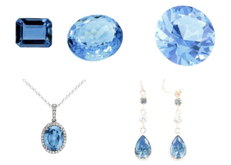
Pierścionek z diamentową oprawą
Spis treści
Sekcja I Zrozumienie JewelCAD
JewelCAD to wspomagany komputerowo system projektowania biżuterii, który został z powodzeniem opracowany przez firmę CAD/CAM z Hongkongu w 1990 roku. Po ponad dekadzie rozwoju i doskonalenia, JewelCAD ewoluował z oprogramowania do rysowania o ograniczonej funkcjonalności w potężne, stabilne, wysoce wyspecjalizowane i wydajne, profesjonalne oprogramowanie do projektowania / produkcji biżuterii, szeroko stosowane w głównych obszarach produkcji biżuterii w Europie, Ameryce i Azji.
Podczas gdy automatyzacja produkcji i przetwarzania w branży jubilerskiej znacznie poprawiła wydajność, JewelCAD pasuje do nowoczesnego projektowania biżuterii i został szeroko rozpowszechniony w obecnych zastosowaniach komercyjnych. Jego unikalne koncepcje modelowania i narzędzia pozwalają projektantom biżuterii na łatwe tworzenie trójwymiarowych obiektów biżuteryjnych, a także doskonale integruje się z szybkim prototypowaniem CNC i RP, co czyni go nowoczesnym oprogramowaniem do projektowania biżuterii z szerokimi perspektywami rozwoju. Jako profesjonalne oprogramowanie do projektowania biżuterii, JewelCAD ma wyraźną przewagę nad innymi programami 3D do tworzenia trójwymiarowych modeli biżuterii, co znajduje odzwierciedlenie w następujących zaletach.
(1) Łatwy w obsłudze, prosty i łatwy do nauczenia.
(2) Posiada elastyczne narzędzia do rysowania, które są bardzo wygodne do rysowania krzywych i złożonych kształtów.
(3) Posiada potężne narzędzia do modelowania powierzchni, które elastycznie tworzą lub modyfikują złożone projekty.
(4) Szybkość renderowania jest duża; można również porównywać różne obrazy efektów projektowych. Jakość obrazów efektów jest wysoka, a symulacja silna. Jest topozwala na obserwację trójwymiarowego efektu, intuicyjnie odzwierciedlając efekt końcowy produktu.
(5) Jego działanie jest bardzo wydajne i odpowiednie do zmiany stylu biżuterii.
(6) Bogata profesjonalna baza danych i różne narzędzia do edycji ułatwiają łączenie i przeprojektowywanie biżuterii, dzięki czemu operacje są wygodniejsze i wydajniejsze.
(7) Zastosowanie zasad operacji Boole'a w oprogramowaniu może łatwo połączyć powierzchnie, które są w stanie swobodnym.
(8) W projekcie wagę złota, ilość i rozmiar można obliczyć bezpośrednio.
(9) Potrafi zbudować bazę danych w celu wizualizacji pomysłów projektowych i poprawy wydajności.
(10) Grafika narysowana za pomocą JewelCAD jest wyraźniejsza i bardziej spójna, co zmniejsza prawdopodobieństwo błędów spowodowanych niejasnym pismem lub niską jakością rysunku. Może bezpośrednio drukować obrazy bez użycia papieru, oszczędzając czas, wysiłek i pieniądze.
Sekcja II Wykorzystanie JewelCAD do przedstawienia podstawowych efektów materiałowych
1. Efekt piaskowania
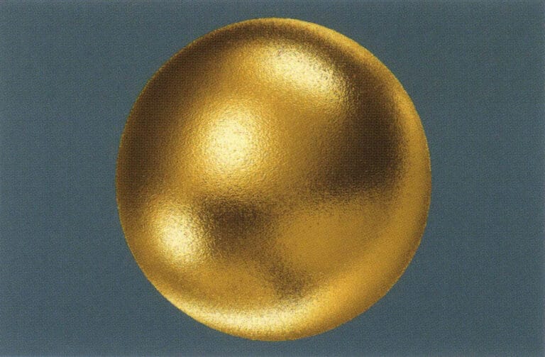
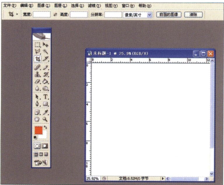
1. Utwórz nowy plik w programie Photoshop z rozdzielczością 300 pikseli/cal
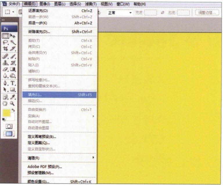
2. Select "Edit" > "Fill" from the menu bar, and set the foreground color to yellow

3. Select "Filter" from the menu bar > "Mottled" > "Add Mottled"
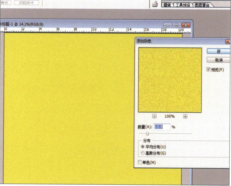
4. Przejdź do okna dialogowego "Add Mottled", wprowadź odpowiednie wartości i potwierdź.
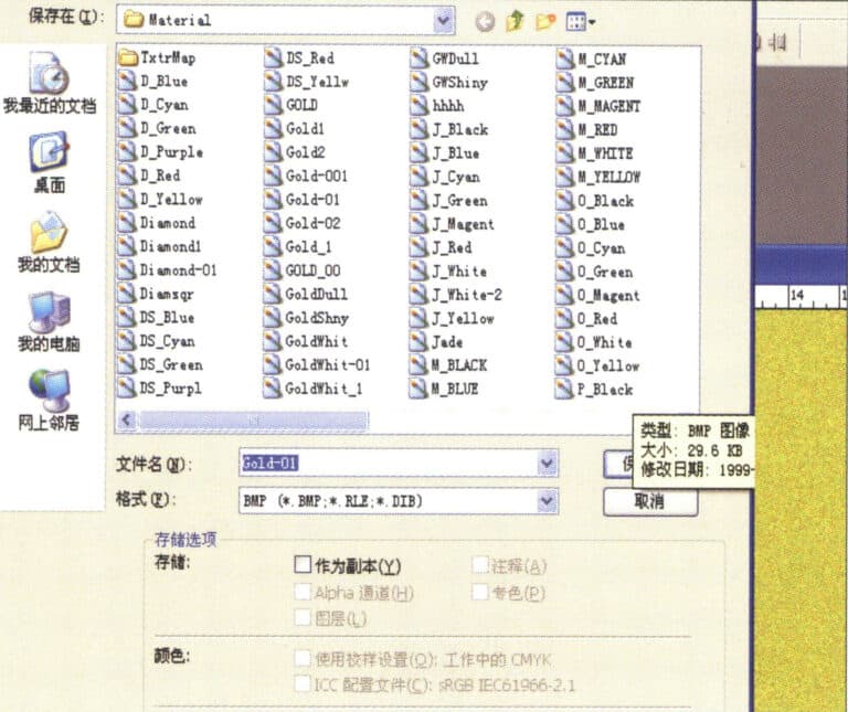
5. Store the document in the "JewelCAD" > "Material" folder, saved in "BMP" format

6. Create a new file in JewelCAD, select "Surface" > "Spherical Surface" from the menu bar
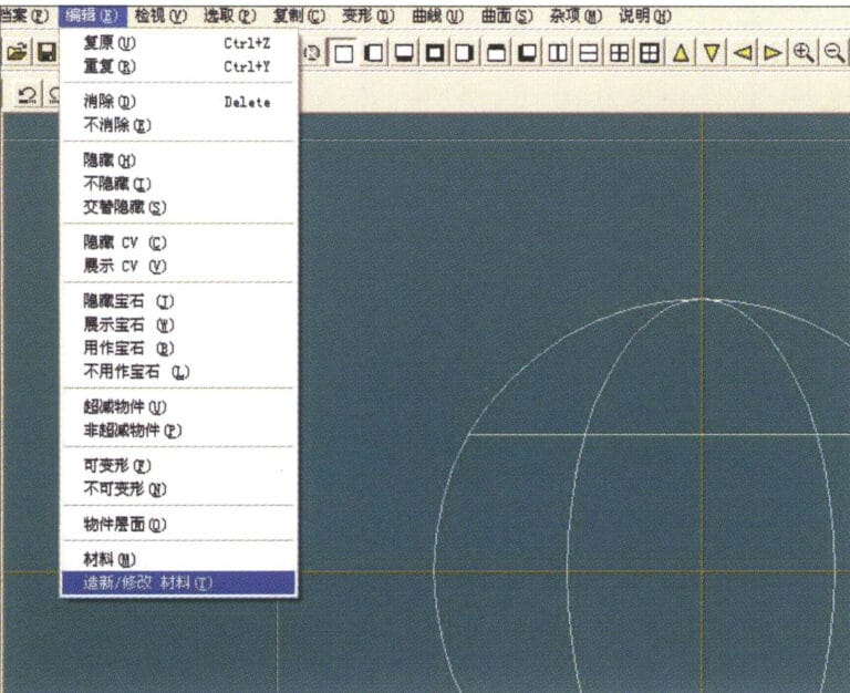
7. Select "Edit" > "Create/Modify Material" from the menu bar
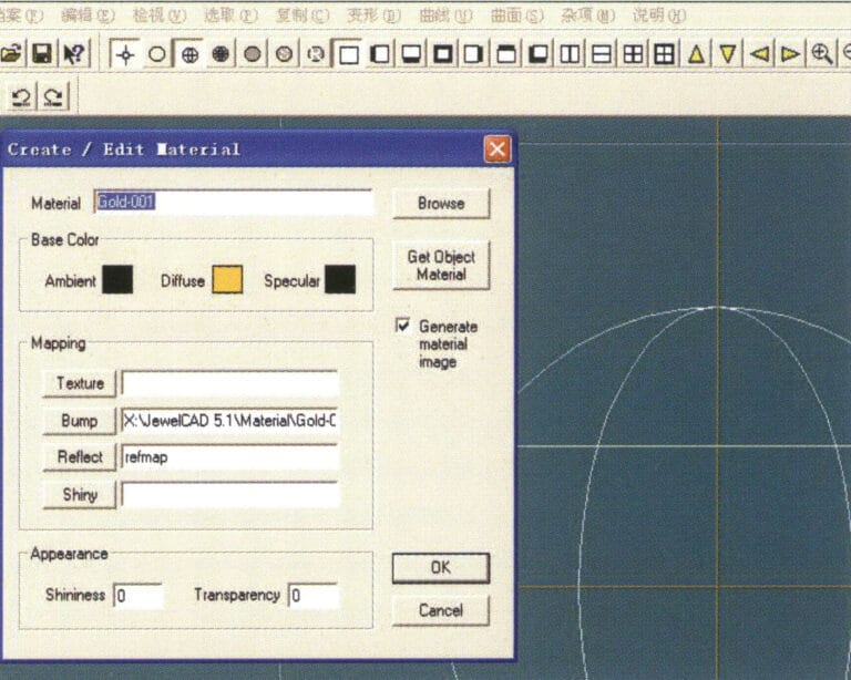
8. Przejdź do okna dialogowego "Create/Modify Material" (Utwórz/Modyfikuj materiał), wprowadź odpowiednie wartości i potwierdź.
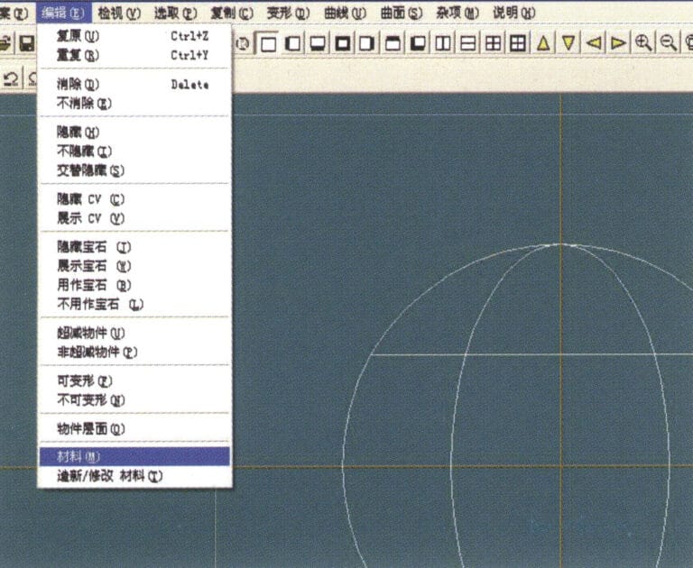
9. Select "Edit" > "Materials" from the menu bar
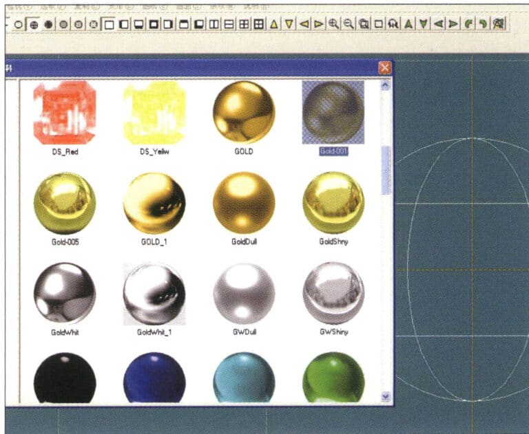
10. Przejdź do okna dialogowego "Materiały", wybierz materiał i potwierdź.
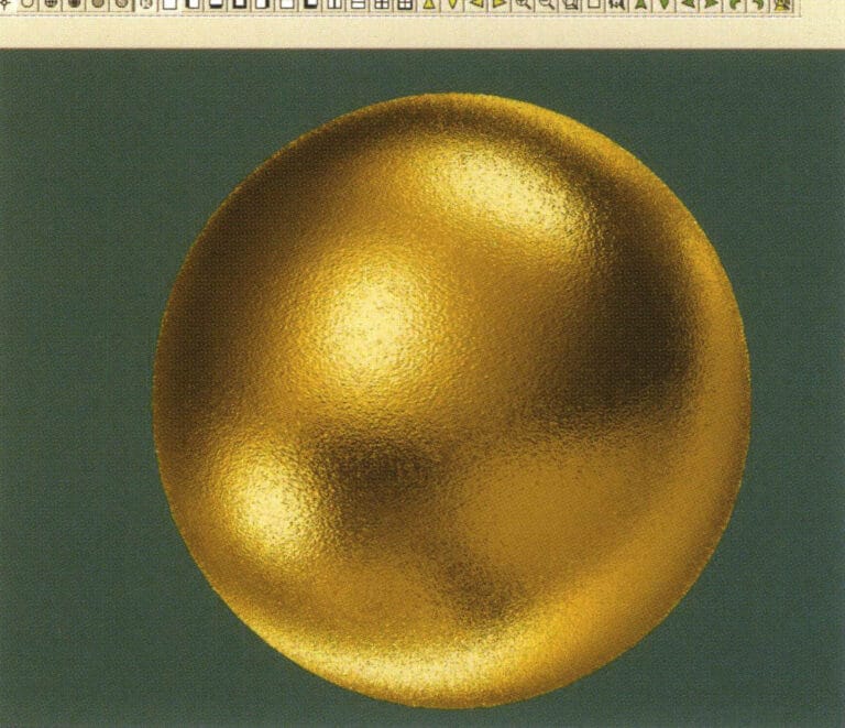
11. Select "View" > "Shadow Map" from the menu bar to inspect the shadow effects.
12. Select "File" > "Save File" from the menu bar to save the document
2. Efekt szczotkowania
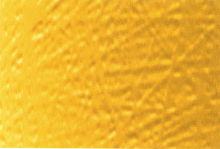

1. Scan a texture file in Photoshop with a resolution of 300 pixels/inch, and select "Filter" > "Blur" > "Motion Blur" from the menu bar to apply the blur effect
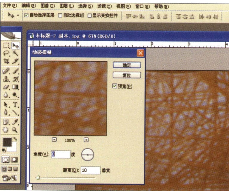
2. Przejdź do okna dialogowego "Motion Blur", wprowadź odpowiednie wartości i potwierdź.
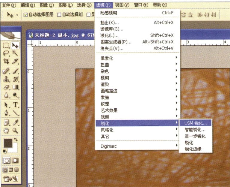
3. Select "Filter" > "Sharpen" > "USM Sharpening" from the menu bar
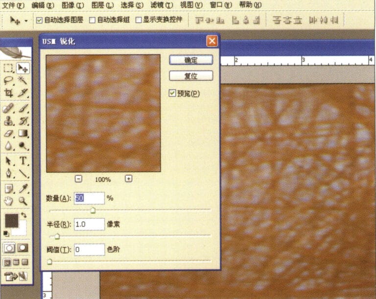
4. Przejdź do okna dialogowego "Wyostrzanie USM", wprowadź odpowiednie wartości i potwierdź.
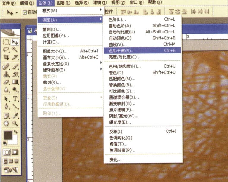
5. Select "Image" > "Adjustments" > "Color Balance" from the menu bar
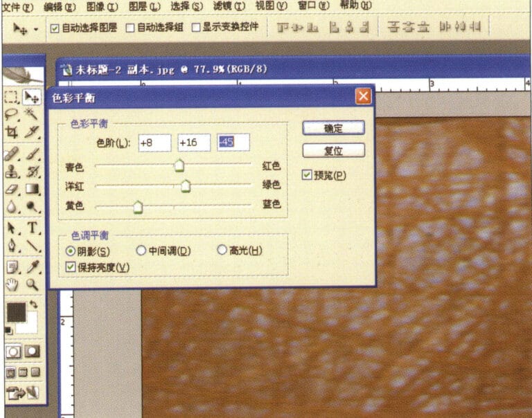
6. Przejdź do okna dialogowego "Balans kolorów", wprowadź odpowiednie wartości i potwierdź.
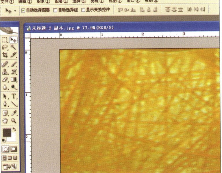
7. Wykres efektu po wyświetleniu balansu kolorów
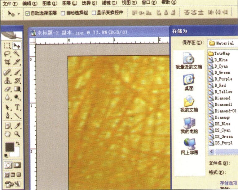
8. Store the document in the "JewelCAD" > "Material" folder, saved in "BMP" format
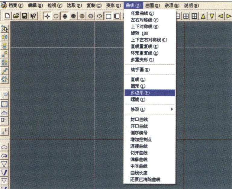
9. In JewelCAD, create a new file, select "Curve" > "Polygon" from the menu bar
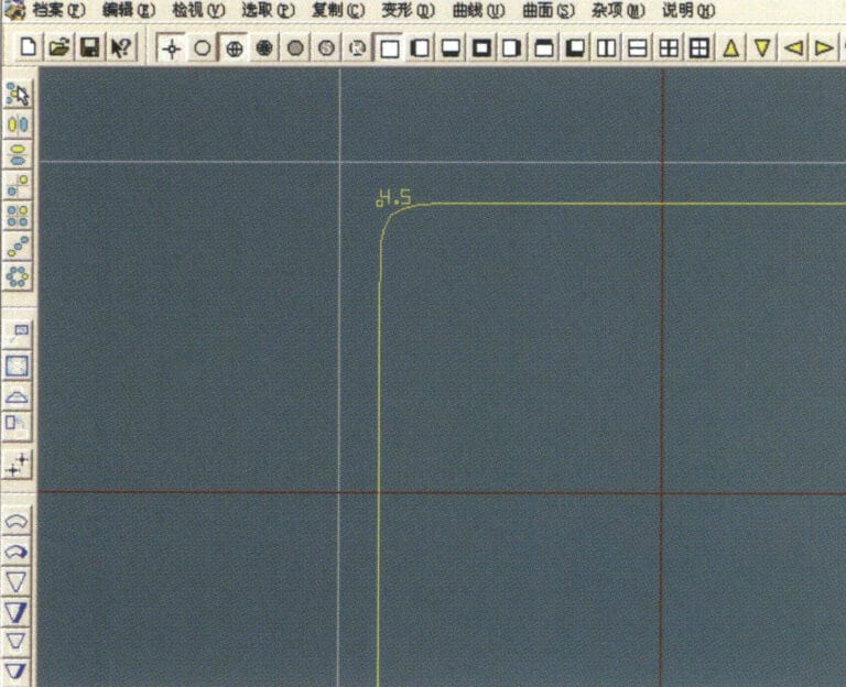
10. Użyj "polygon", aby narysować kwadrat
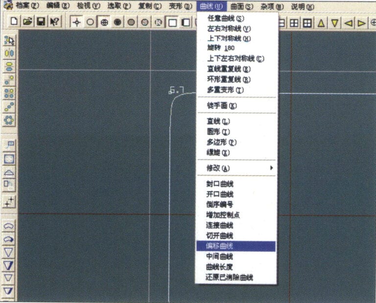
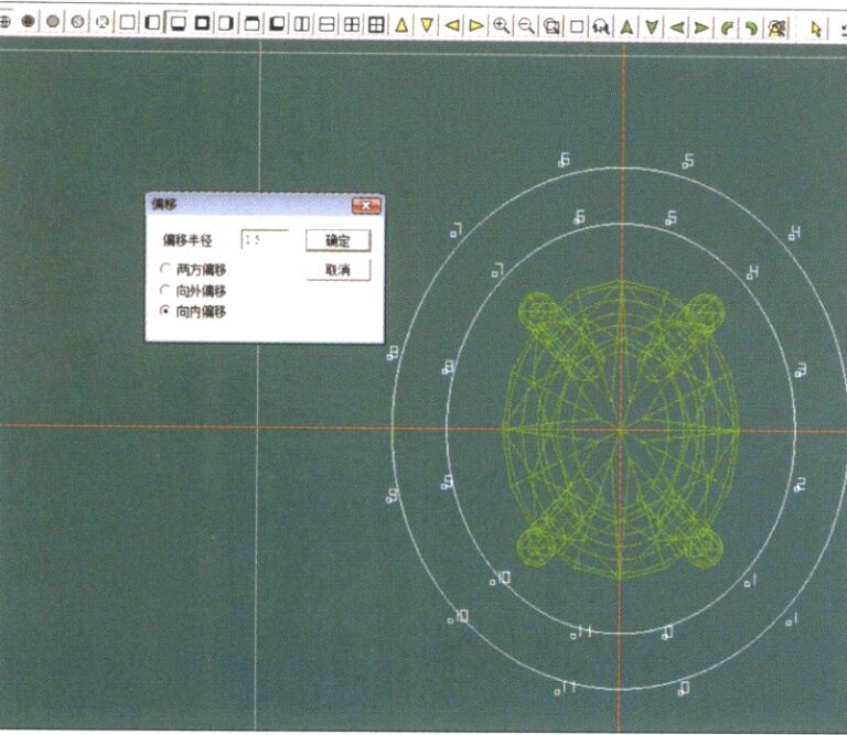
11. Select "Curve" > "Offset Curve" from the menu bar
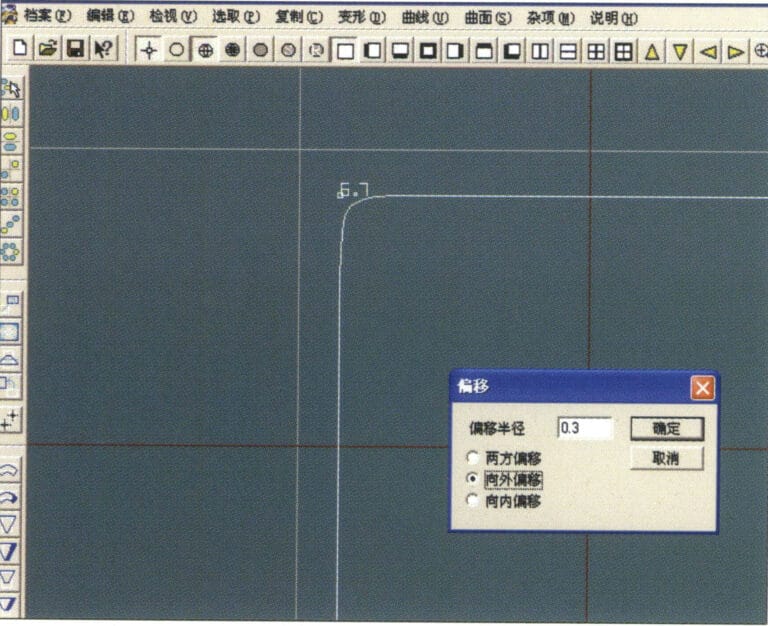
12. Przejdź do okna dialogowego "Offset Curve" (Krzywa przesunięcia), wprowadź odpowiednie wartości i potwierdź.
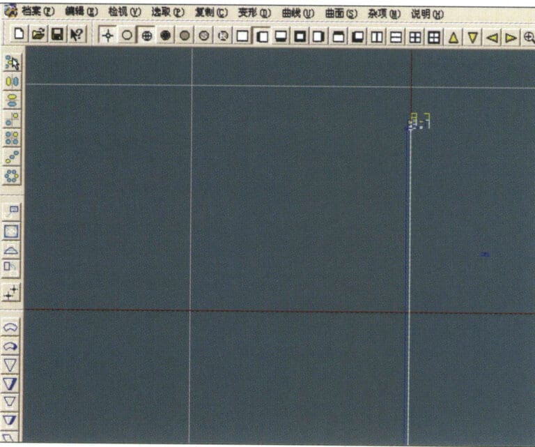
13. Wykres efektu po wyświetleniu krzywej przesunięcia
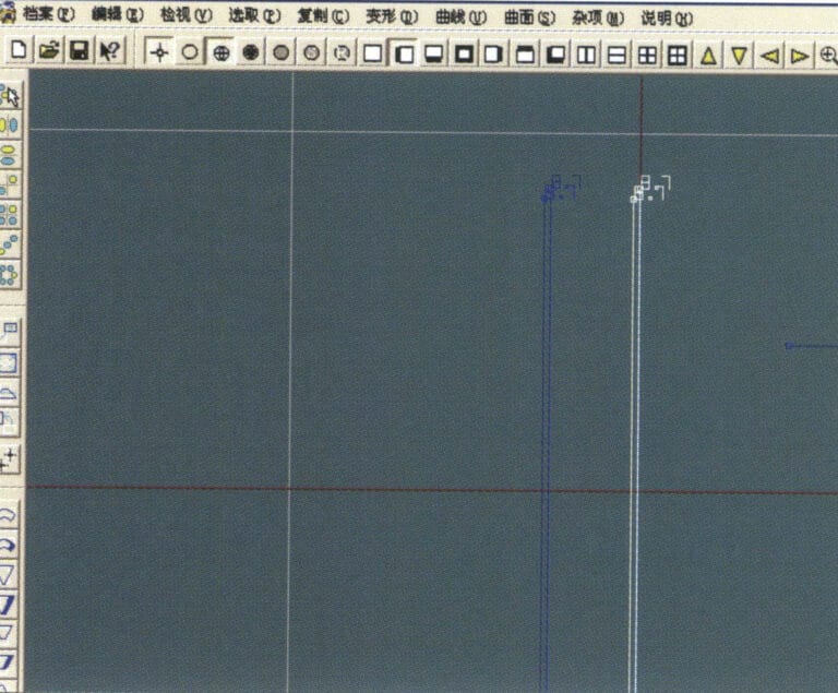
14. Select "Deformation" > "Move" from the menu bar to move the selected curve
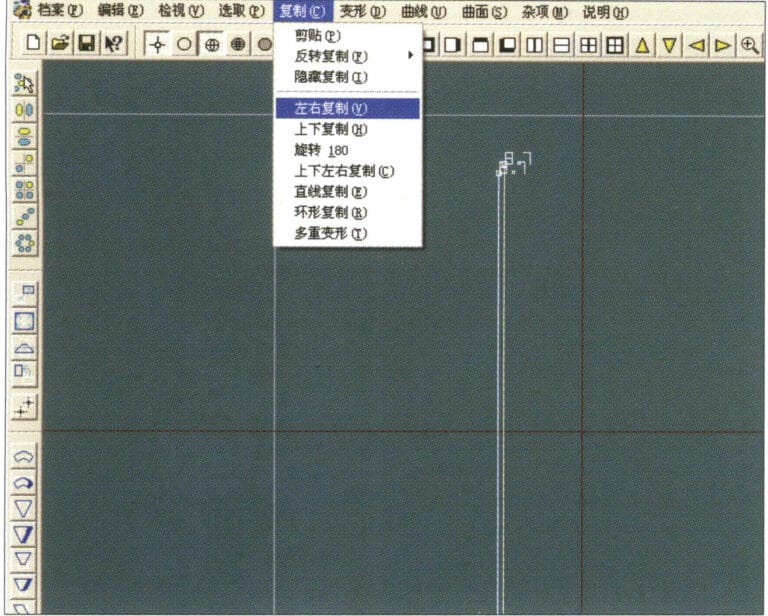
15. Select "Copy" > "Copy Left and Right" from the menu bar to copy the selected curve to the left and right
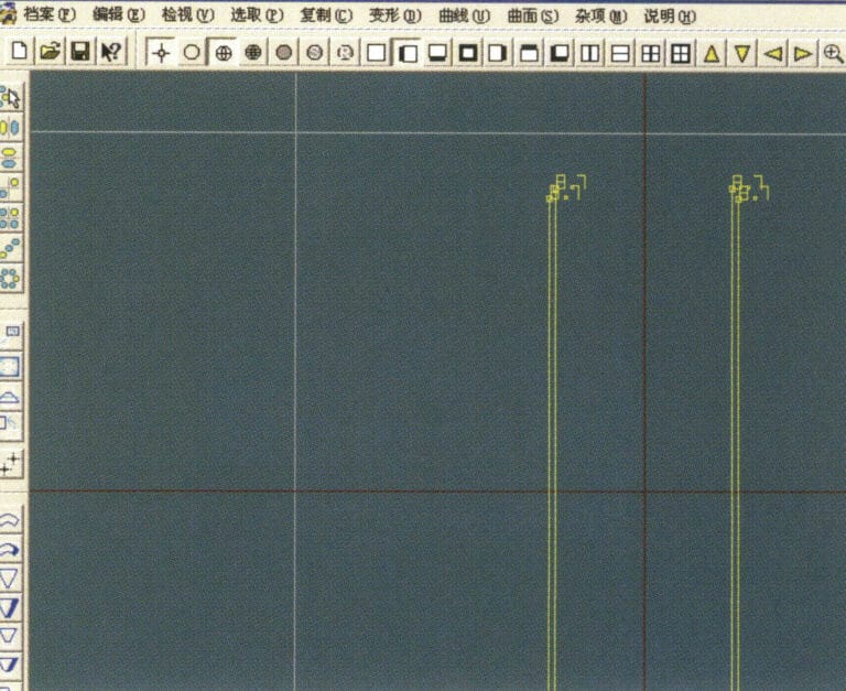
16. Wyświetlanie obrazów efektów po powieleniu z lewej i prawej strony
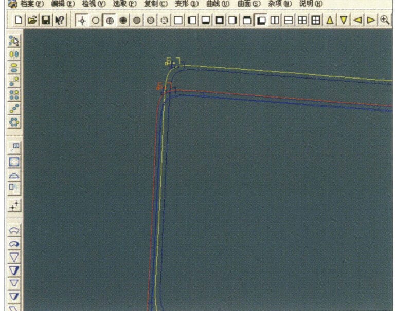
17. Select "Surface" > "Curve Surface Connection" from the menu bar, and double-click the first and second curves/surfaces in a clockwise direction with the left mouse button to create a curve surface connection
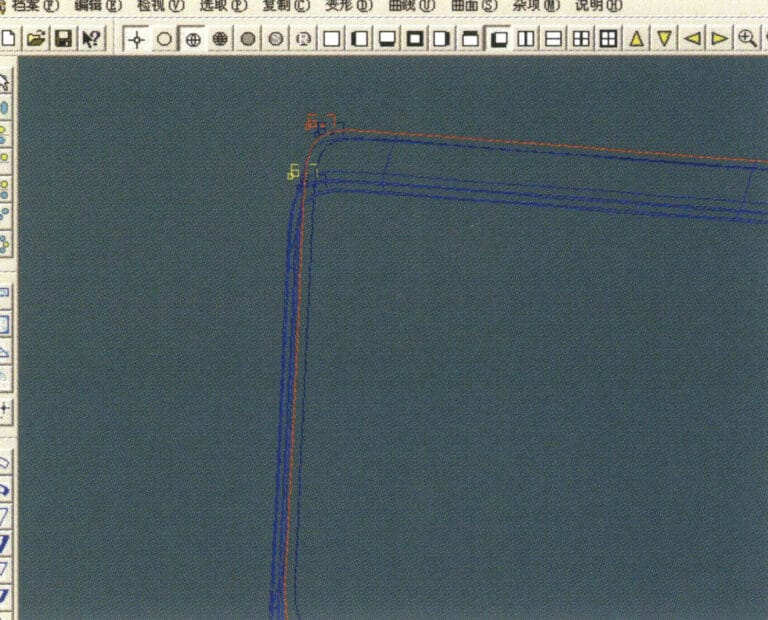
18. W kierunku zgodnym z ruchem wskazówek zegara kliknij dwukrotnie trzecią krzywą/powierzchnię lewym przyciskiem myszy, aby utworzyć połączenie linia-powierzchnia
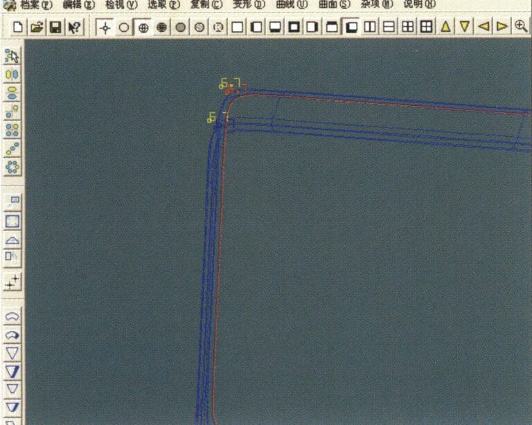
19. Kontynuuj zgodnie z ruchem wskazówek zegara; kliknij dwukrotnie czwartą krzywą/powierzchnię lewym przyciskiem myszy, aby utworzyć połączenie linia-powierzchnia

20. Select "View" > "Shadow Map" from the menu bar to inspect the shadow effects
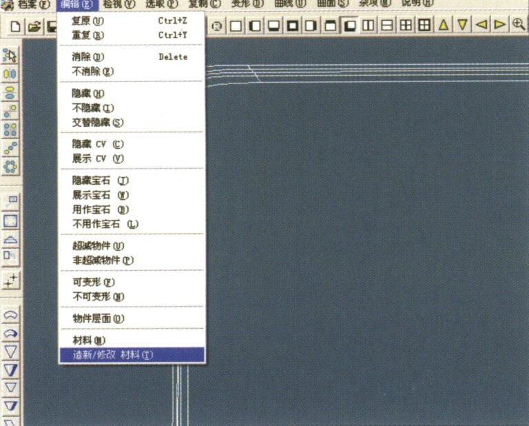
21. Select "Edit" > "Create/Modify Material" from the menu bar
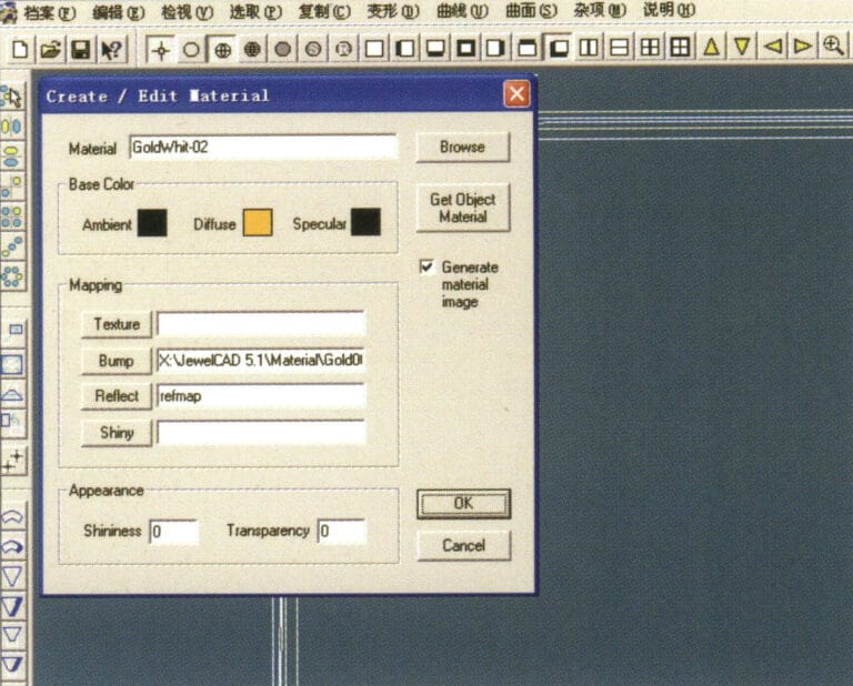
22. Przejdź do okna dialogowego "Create/Modify Material" (Utwórz/Modyfikuj materiał), wprowadź odpowiednie wartości i potwierdź.
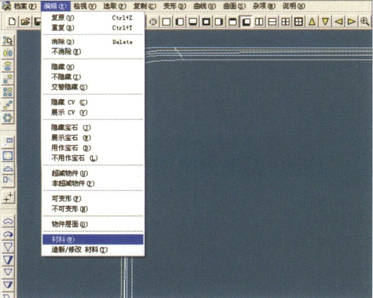
23. Select "Edit" > "Materials" from the menu bar
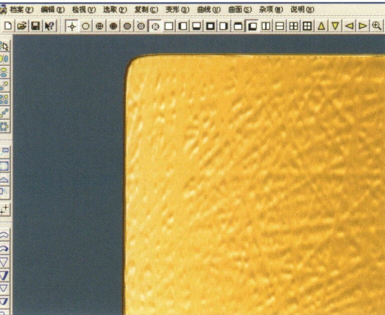
24. Select "View" > "Shadow Map" on the menu bar to view the light and shadow effects 25. Select "File" > "Save File" on the menu bar to save the file
3. Wykończenie o fakturze kory
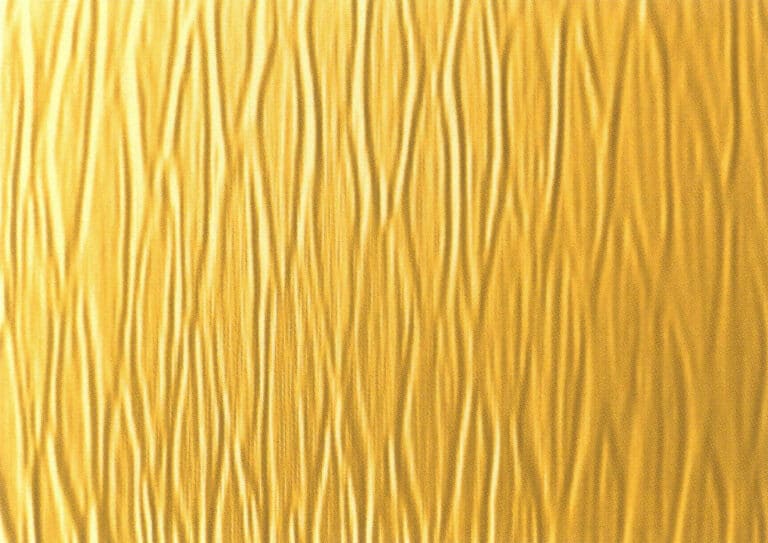

1. Zeskanuj plik tekstury do programu Photoshop z rozdzielczością 300 pikseli/cal
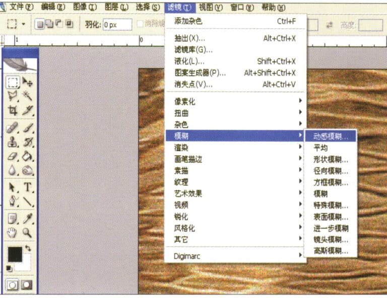
2. Select "Filter" > "Blur" > "Motion Blur" from the menu bar
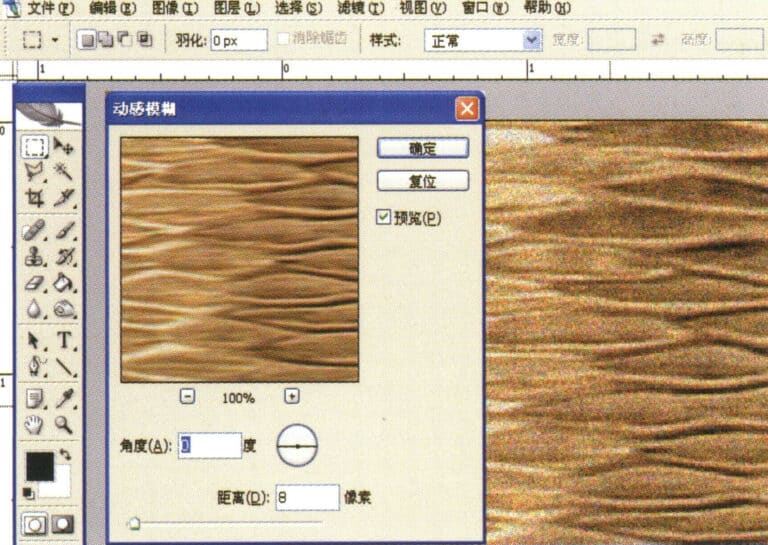
3. Przejdź do okna dialogowego "Motion Blur", wprowadź odpowiednie wartości i potwierdź.
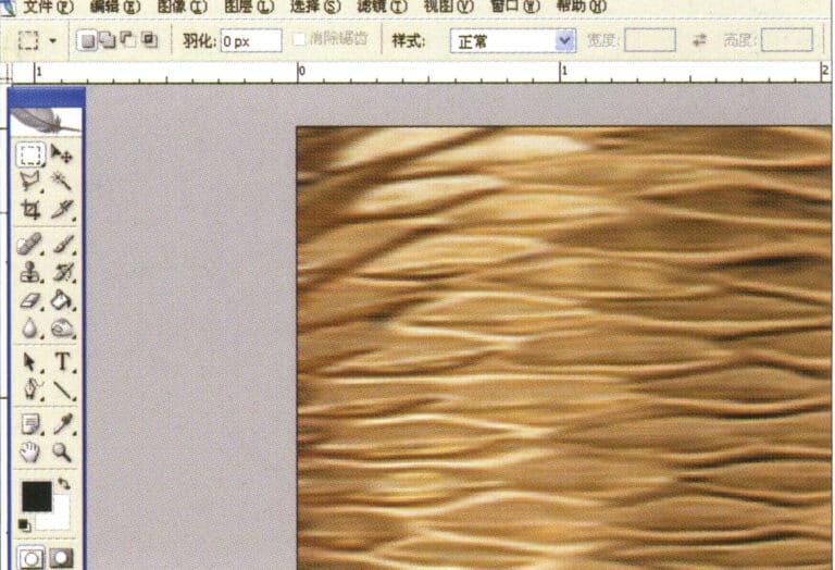
4. Wyświetlanie obrazu efektu po rozmyciu ruchu
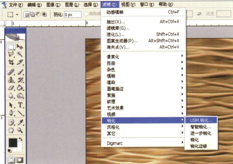
5. Select "Filter" > "Sharpen" > "USM Sharpening" from the menu bar
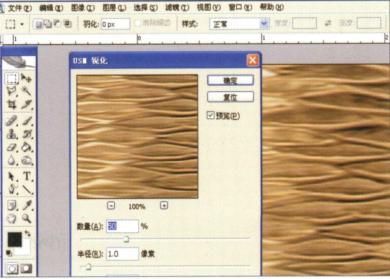
6. Przejdź do okna dialogowego "Wyostrzanie USM", wprowadź odpowiednie wartości i potwierdź.
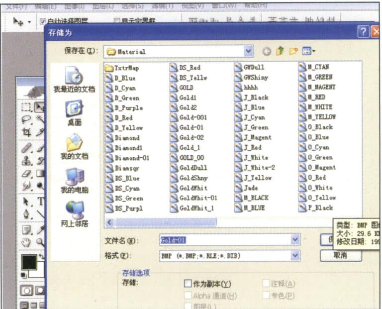
7. Store the document in the "JewelCAD" > "Material" folder and save it in "BMP" format
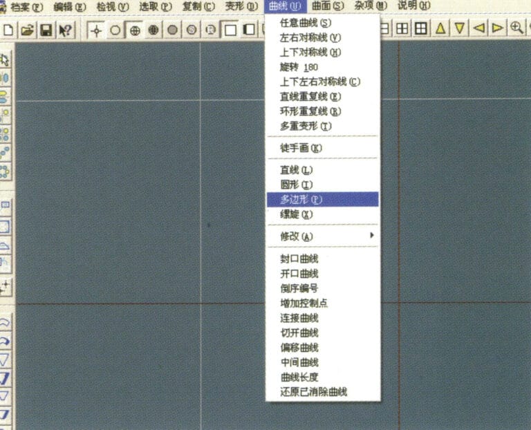
8. In JewelCAD, create a new file, select "Curve" > "Polygon" from the menu bar
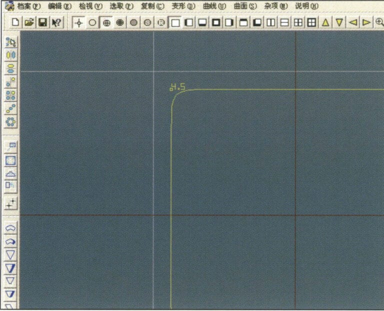
9. Użyj "polygon", aby narysować kwadrat
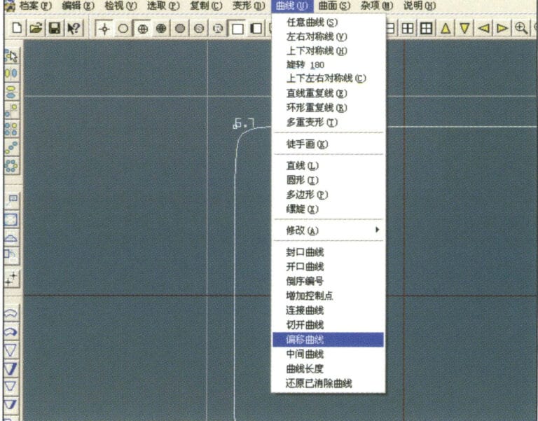
10. Select "Curve" > "Offset Curve" from the menu bar
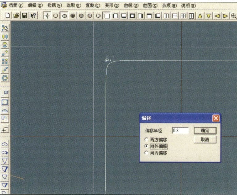
11. Przejdź do okna dialogowego "Offset Curve" (Krzywa przesunięcia), wprowadź odpowiednie wartości i potwierdź.
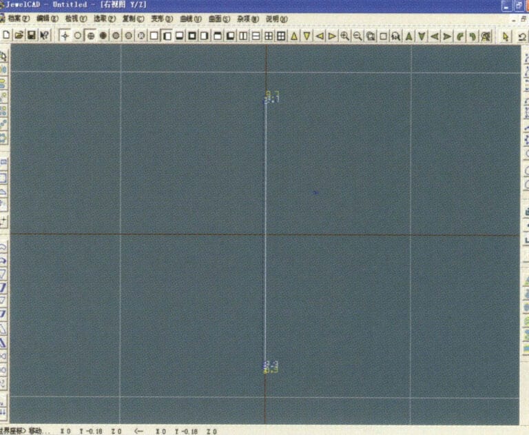
12. Wykres efektu po wyświetleniu krzywej przesunięcia
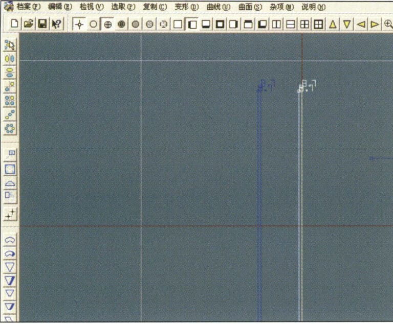
13. Select "Deformation" > "Move" from the menu bar to move the selected curve
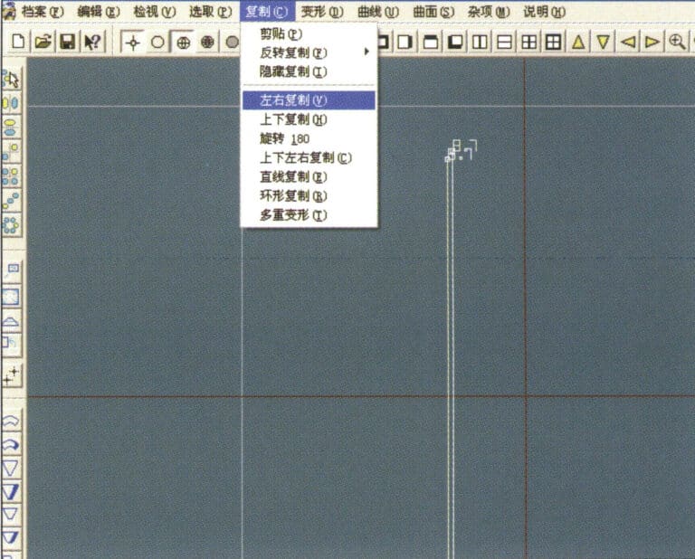
14. Select "Copy" > "Copy Left and Right" from the menu bar to copy the selected curve to the left and right
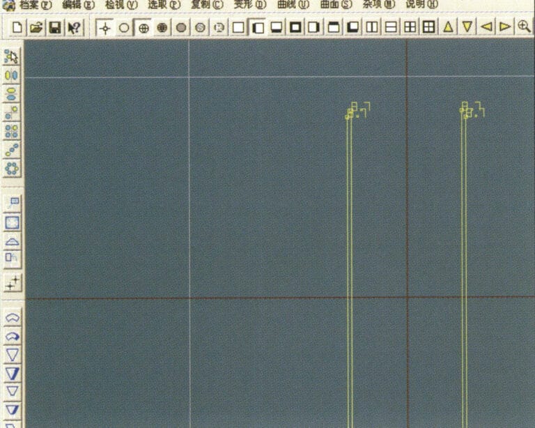
15. Wyświetlanie obrazów efektów po skopiowaniu lewej i prawej strony
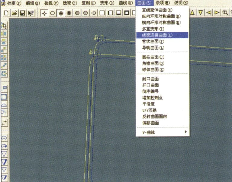
16. Select "Surface" > "Line-Surface Connection Surface" from the menu bar, and select the curve/surface to create a line-surface connection surface
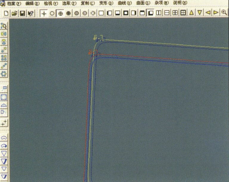
17. Select the menu bar "Surface" > "Curve Surface Connection," and double-click the first and second curves/surfaces with the left mouse button in a clockwise direction to create a curve surface connection
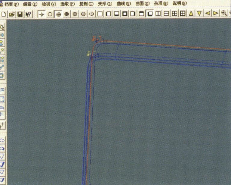
18. W kierunku zgodnym z ruchem wskazówek zegara kliknij dwukrotnie trzecią krzywą/powierzchnię lewym przyciskiem myszy, aby utworzyć połączenie linia-powierzchnia
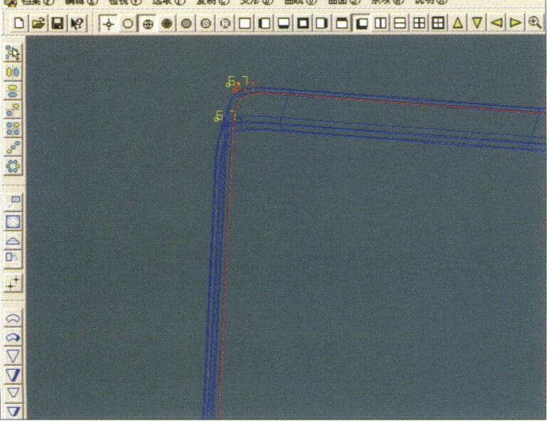
19. Kontynuuj zgodnie z ruchem wskazówek zegara; kliknij dwukrotnie czwartą krzywą/powierzchnię lewym przyciskiem myszy, aby utworzyć połączenie linia-powierzchnia
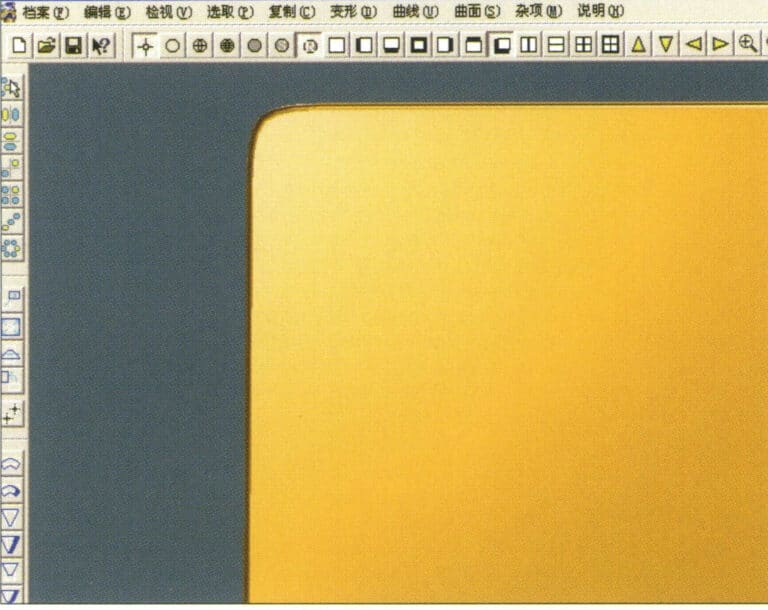
20. Select "View" > "Shadow Map" from the menu bar to inspect the shadow effects
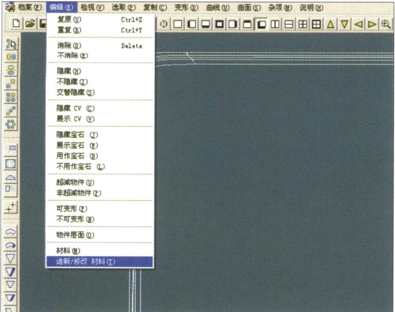
21. Select "Edit" > "Create/Modify Material" from the menu bar
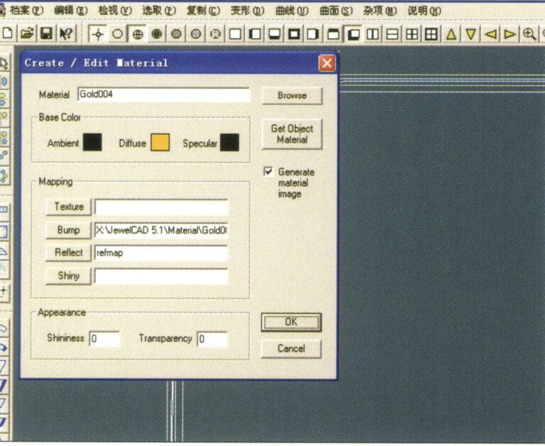
22. Przejdź do okna dialogowego "Create/Modify Material" (Utwórz/Modyfikuj materiał), wprowadź odpowiednie wartości i potwierdź.
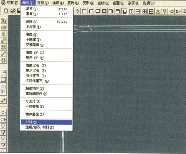
23. Select “Edit” > “Material” in the menu bar
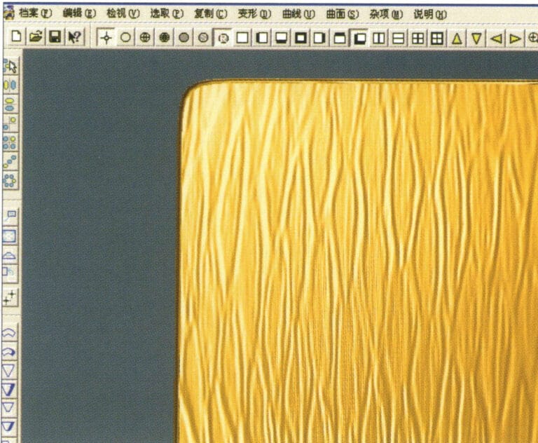
24. Select "View" > "Shadow Map" from the menu bar to examine the shadow effects
25. Select "File" > "Save As" from the menu bar to save the file
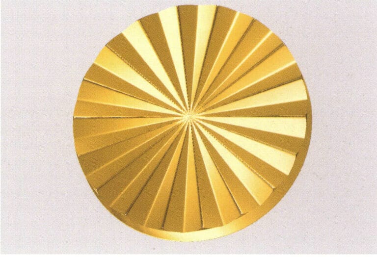
4. Wykończenie toczone maszynowo

1. Create a new file in JewelCAD, select "Curve" > "Circular Curve" from the menu bar, enter the relevant values in the "Circular Curve" dialog box, and confirm
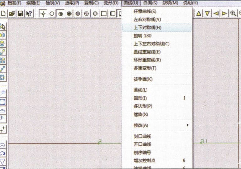
2. Select "Curve" > "Left-Right Symmetry Line" from the menu bar to draw a section
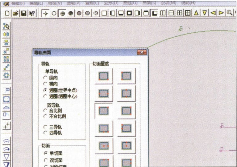
3. Select "Surface" > "Rail Surface" from the menu bar, enter "Rail Surface," select the relevant options and confirm; left-click on a curve as the section of the rail surface; left-click on another curve as the "Rail" > "Finish."

4. Select “View” > “Shadow Map” on the menu bar to view the light and shadow effects
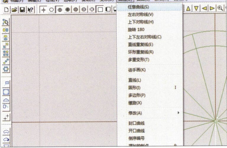
5. Select "Curve" > "Freefrom Curve" from the menu bar
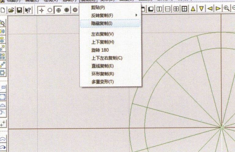
6. Select "Copy" > "Hide Copy" from the menu bar
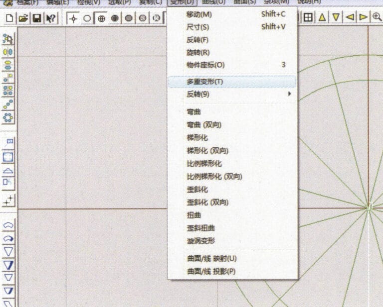
7. Select "Deformation" > "Multiple Deformation" from the menu bar
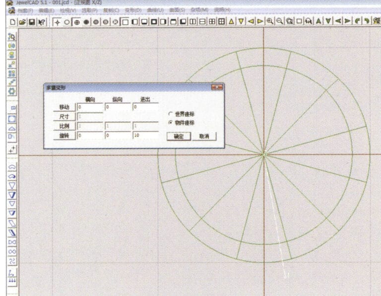
8. Przejdź do okna dialogowego "Multiple Deformation" i wprowadź odpowiednie wartości
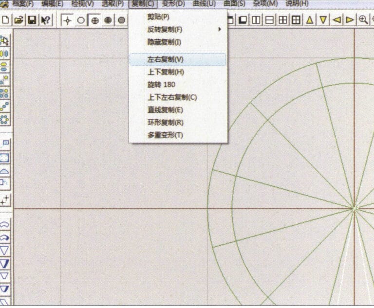
9. Select “Copy” > “Left/Right Copy” on the menu bar
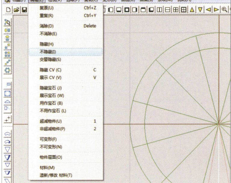
10. Select "Edit" > "Unhide" from the menu bar to display the hidden curves
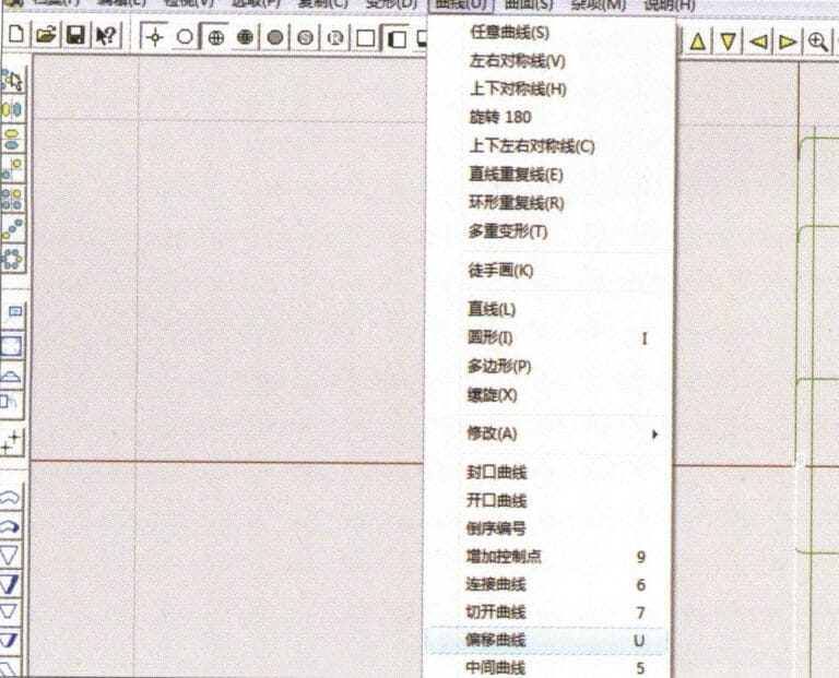
11. Select "Curve" > "Offset Curve" from the menu bar
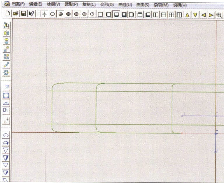
12. Select "Deformation" > "Move" from the menu bar to move the selected curve
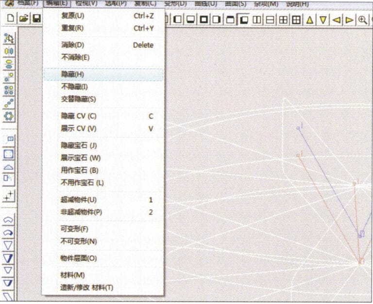
13. Select "Edit" > "Hide" from the menu bar to hide the circular surface
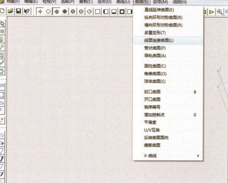
14. Select "Surface" > "Line Surface Connection Surface" from the menu bar

15. Wybierz krzywe/powierzchnie w kierunku zgodnym z ruchem wskazówek zegara, aby utworzyć połączenia linia-powierzchnia, a następnie wybierz z paska menu opcję
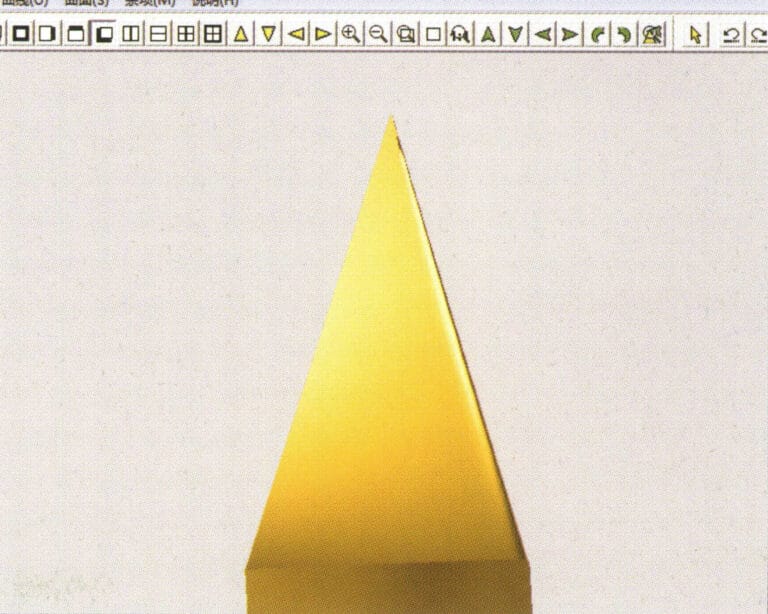
16. Select "View" > "Shadow Map" from the menu bar to inspect the shadow effects
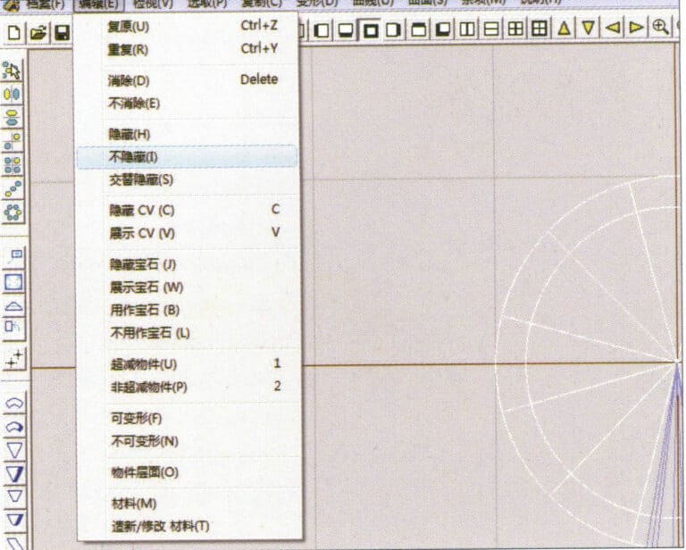
17. Select "Edit" > "Unhide" from the menu bar to display the hidden circular surfaces
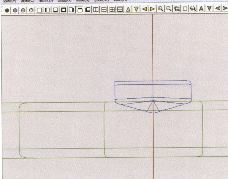
18. Select "Deformation" > "Move" from the menu bar to move the selected surface
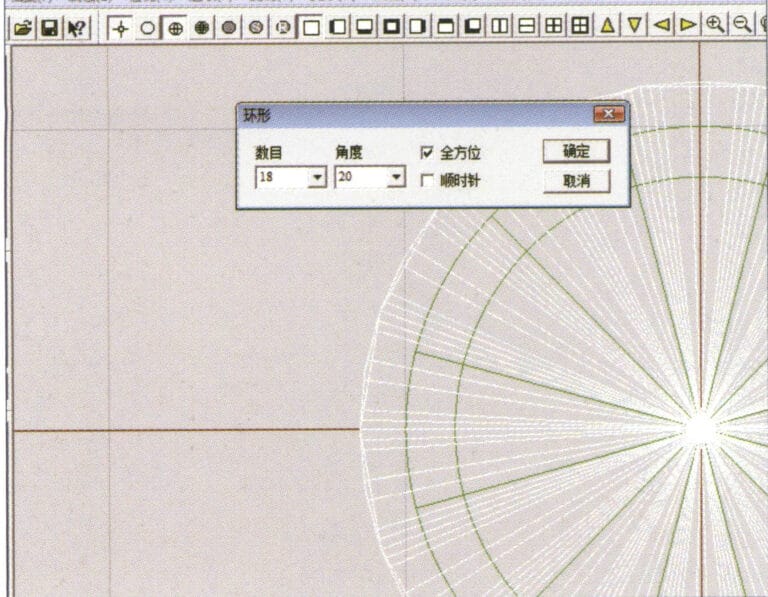
19. Select "Copy" > "Circular Copy" from the menu bar, enter the relevant values and confirm

20. Select “Miscellaneous” > “Boolean” > “Integrate” on the menu bar to integrate the selected surfaces.
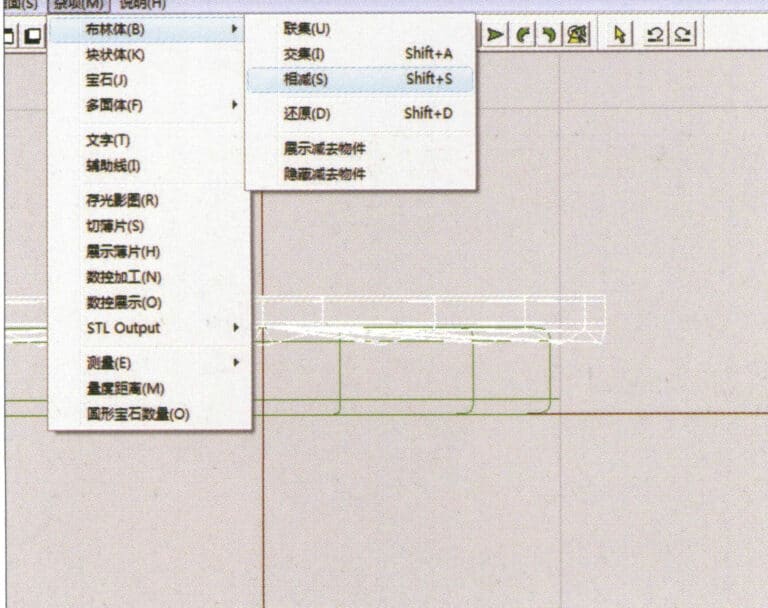
21. Select "Miscellaneous" > "Boolean" > "Subtract" from the menu bar to subtract the selected surface from the already united surface
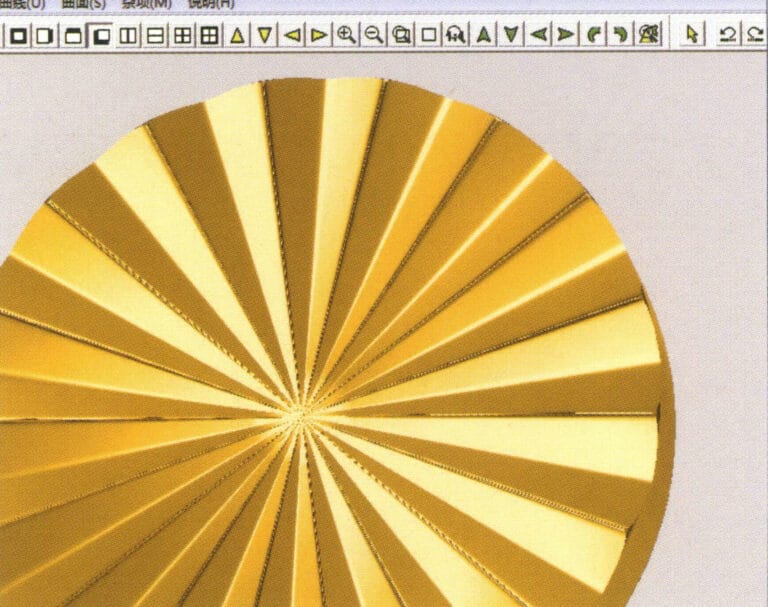
22. Select "View" > "Shadow Map" from the menu bar to inspect the shadow effects.
23. Select "File" > "Save File" from the menu bar to save the document
Sekcja III Korzystanie z JewelCAD do tworzenia efektów biżuterii
1. Pierścionek z diamentem
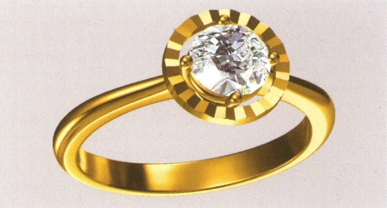
Etapy produkcji są następujące:
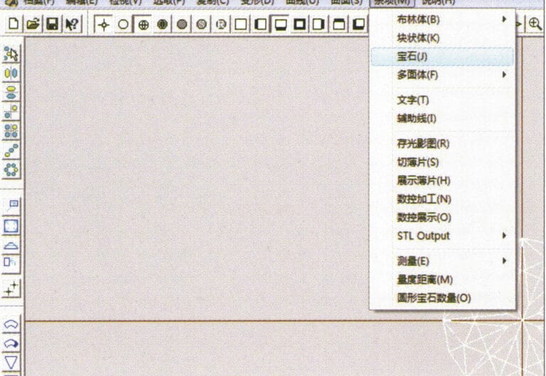
1. Create a new file in JewelCAD, select "Miscellaneous" > "Gem" from the menu bar

2. Select "Deformation" > "Multiple Deformation" from the menu bar
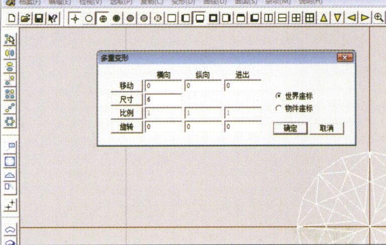
3. Przejdź do okna dialogowego "Multiple Deformation", wprowadź odpowiednie wartości i potwierdź.
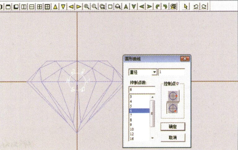
4. Select “Curve” > “Circular Curve” in the menu bar to enter the “Circular Curve” dialog box, enter the relevant values and confirm
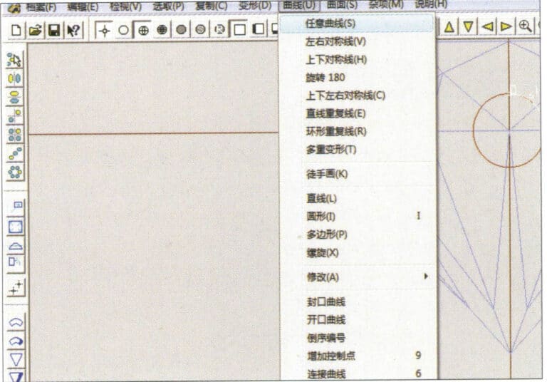
5. Select "Curve" > "Freeform Curve" from the menu bar to draw a claw-shaped guideline
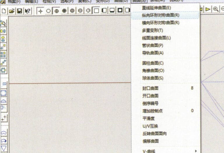
6. Select "Surface" > "Longitudinal Annular Symmetrical Surface" from the menu bar, and draw a claw shape
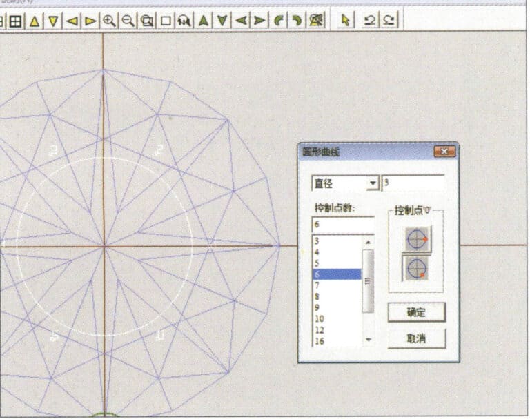
7. Select "Curve" > "Circular Curve" from the menu bar, enter the relevant values in the "Circular Curve" dialog box and confirm
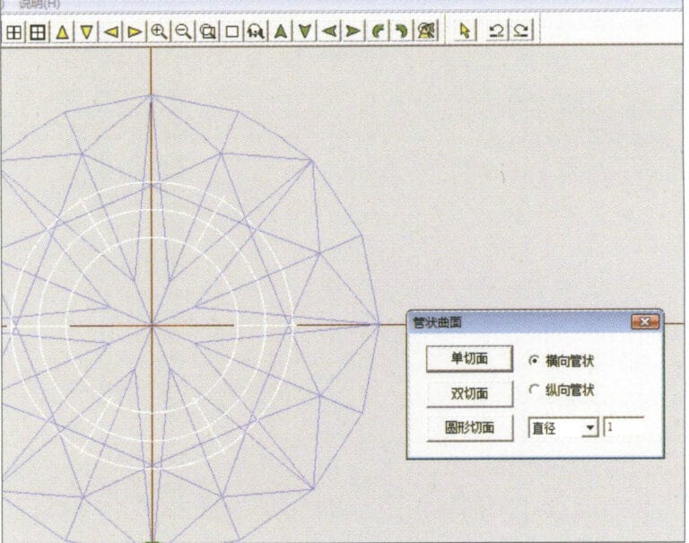
8. Select "Surface" > "Tubular Surface" from the menu bar, enter the relevant values and confirm
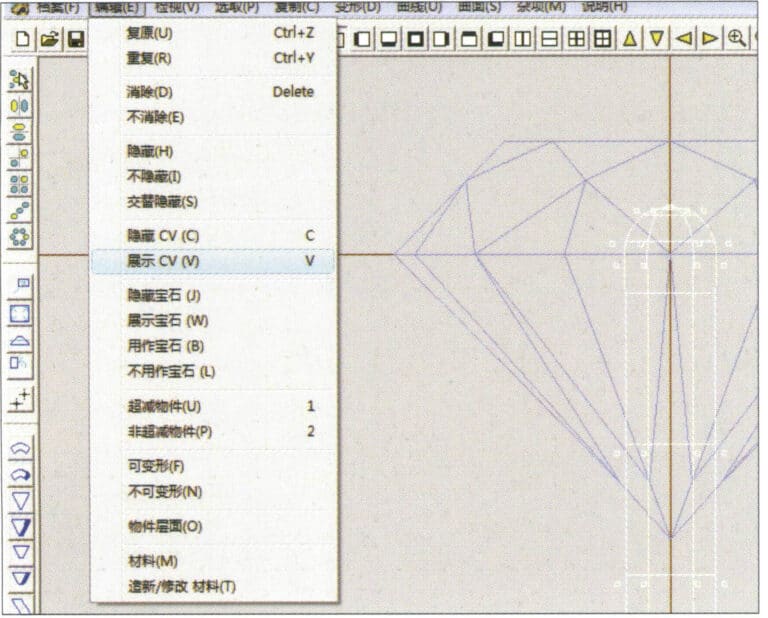
9. Select “Edit” > “Show CV” in the menu bar
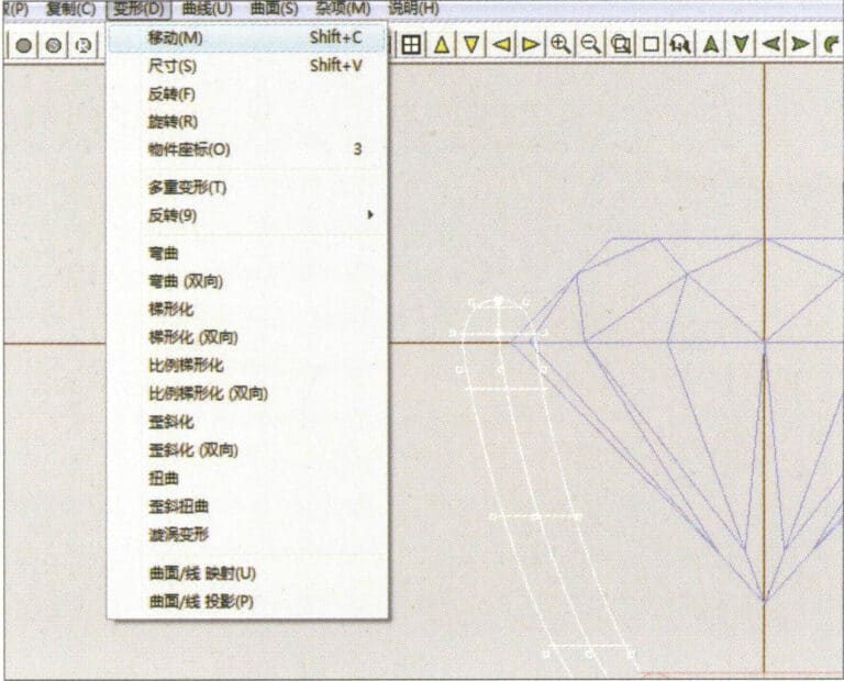
10. Select “Deformation” > “Move” in the menu bar to move the CV
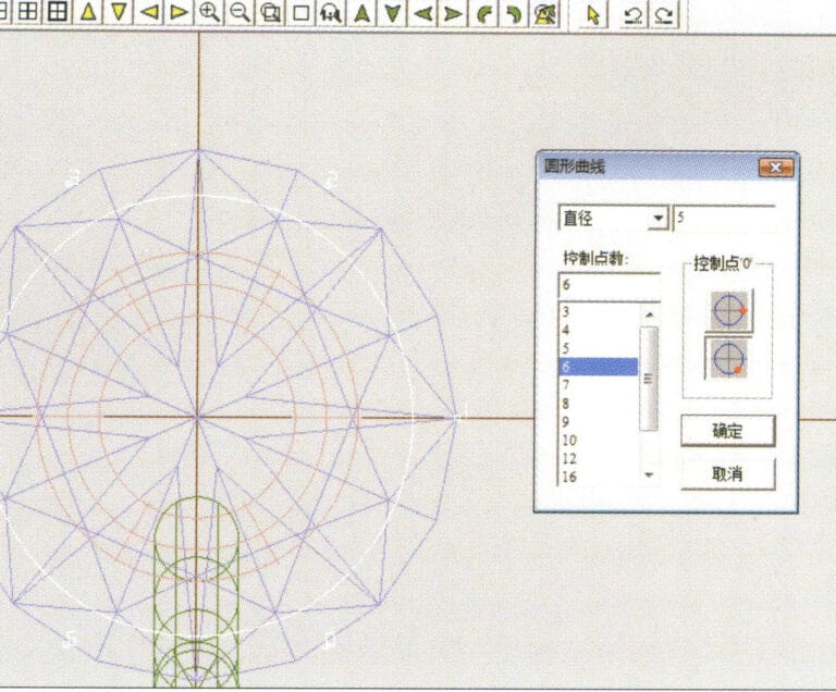
11. Select "Curve" > "Circular Curve" from the menu bar, enter the relevant values in the "Circular Curve" dialog box and confirm
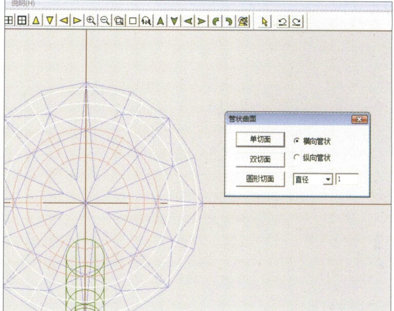
12. Select "Surface" > "Tubular Surface" from the menu bar, enter the relevant values and confirm
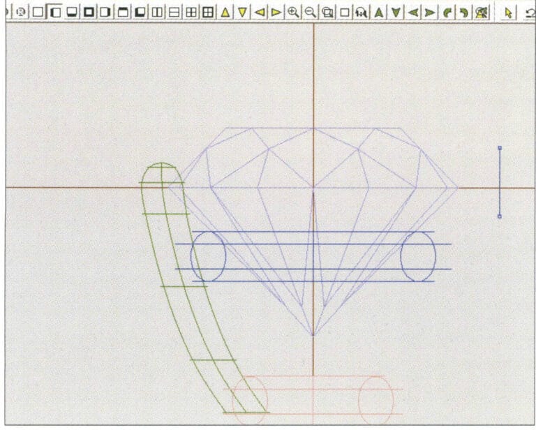
13. Select the menu bar "Edit" > "Move" to move the selected graphic

14. Select the completed claw shape, choose "Copy" > "Circular Copy" from the menu, enter the relevant values in the "Circular Copy" dialog box and confirm
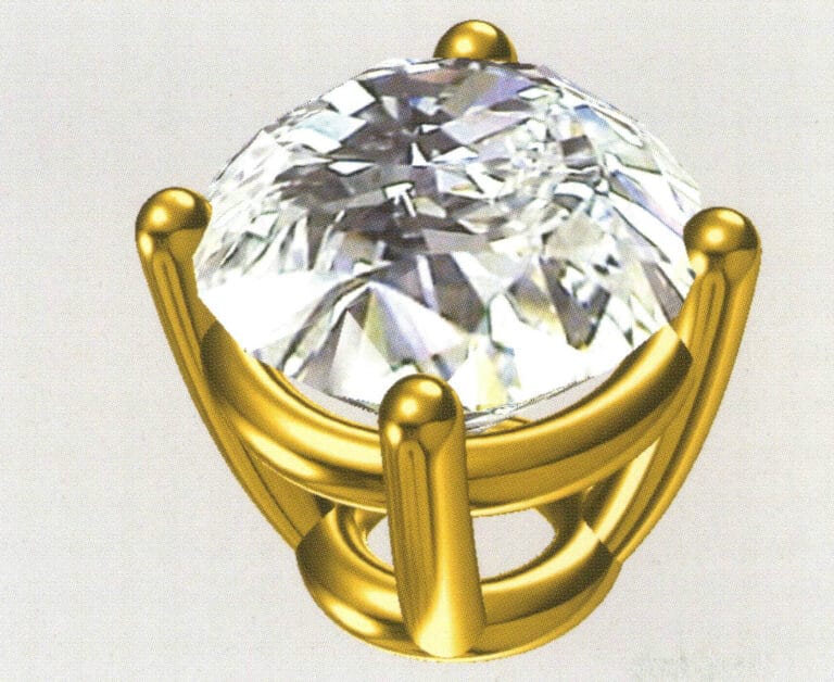
15. Select "View" > "Shadow Map" from the menu bar to inspect the shadow effects
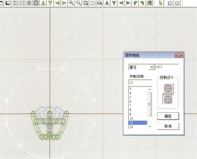
16. Select "Curve" > "Circular Curve" from the menu bar, enter the "Circular Curve" dialog box, and input the relevant values as the inner diameter of the ring shank
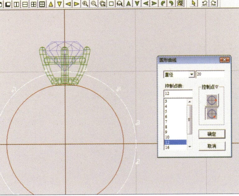
17. Select "Curve" > "Circular Curve" from the menu bar, enter the "Circular Curve" dialog box, and input the relevant values as the outer diameter of the ring shank

18. Select "Curve" > "Circular Curve" from the menu bar, enter the "Circular Curve" dialog box, and input the relevant values as the outer diameter of the engine-turned band
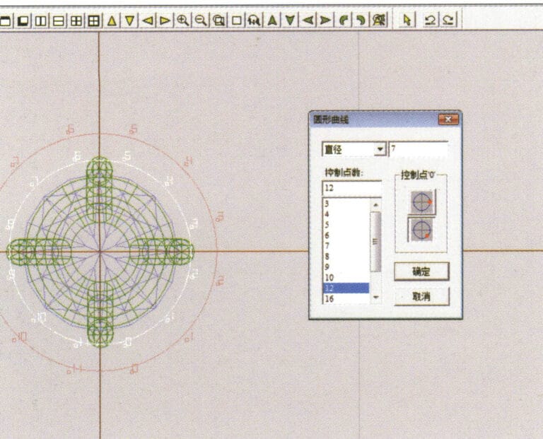
19. Select "Curve" > "Circular Curve" from the menu bar, enter the "Circular Curve" dialog box, and input the relevant values as the inner diameter of the engine-turned band
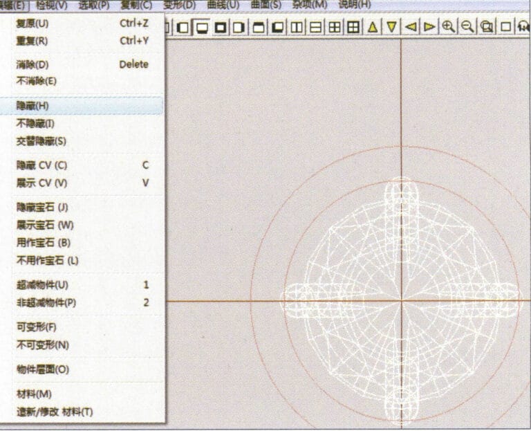
20. Select "Edit" > "Hide" from the menu bar to hide the completed gemstone inlay
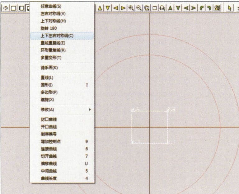
21. Select "Curve" > "Vertical and Horizontal Symmetry Line" from the menu bar
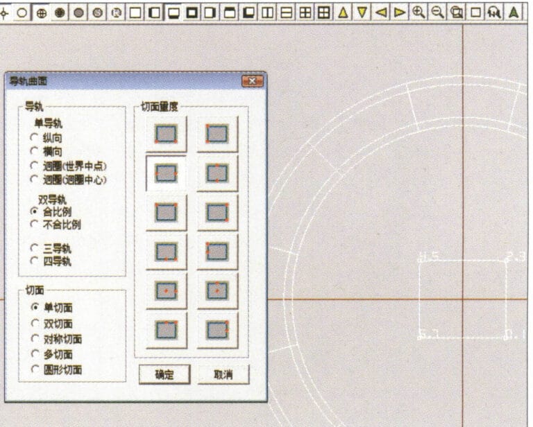
22. Select "Surface" > "Rail Surface" from the menu bar to enter the "Rail Surface" dialog box, select the relevant options and confirm
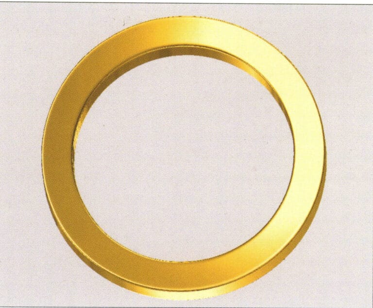
23. Select "View" > "Shadow Map" from the menu bar to inspect the shadow effects
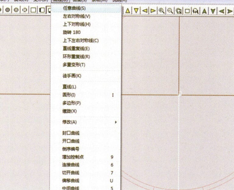
24. Select "Curve" > "Freeform Curve" from the menu bar to draw a guideline

25. Select "Copy" > "Hide Copy" from the menu bar to copy the already drawn auxiliary lines
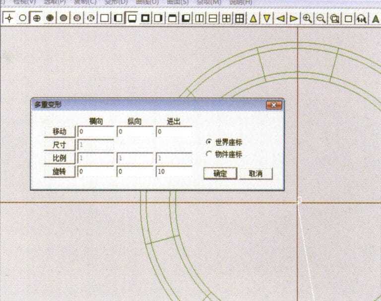
26. Select “Deformation” > “Multiple Deformation” in the menu bar to enter the “Multiple Deformation” dialog box, enter the relevant values and confirm
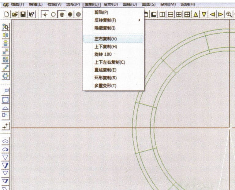
27. Select “Copy” > “Copy Up and Down” in the menu bar to copy the drawn auxiliary lines
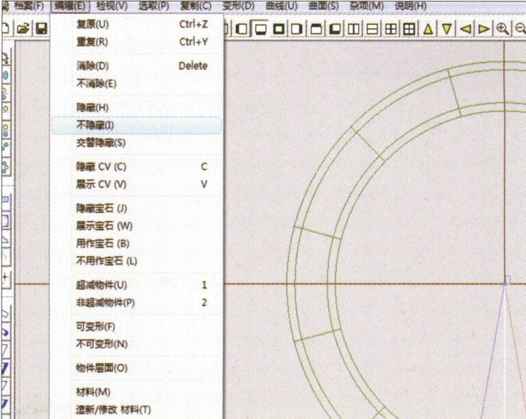
28. Select "Edit" > "Unhide" from the menu to display the hidden curves
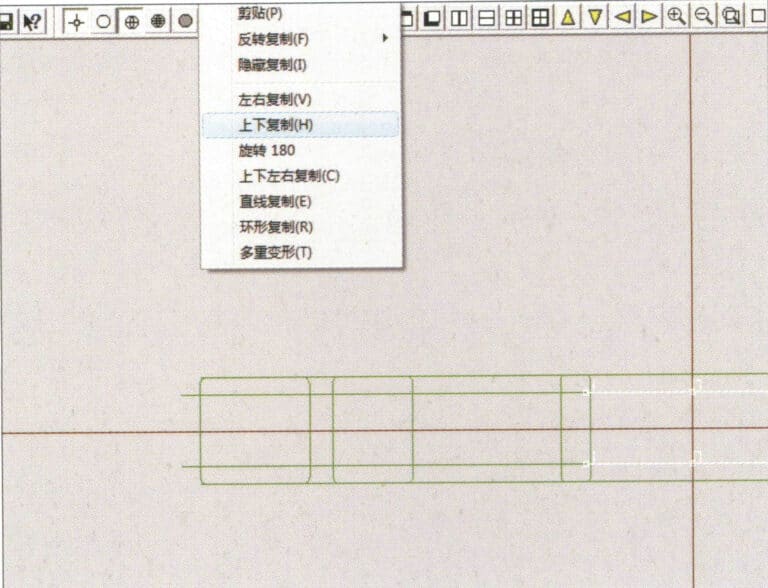
29. Select "Copy" > "Copy Up and Down" from the menu bar to copy the selected curve
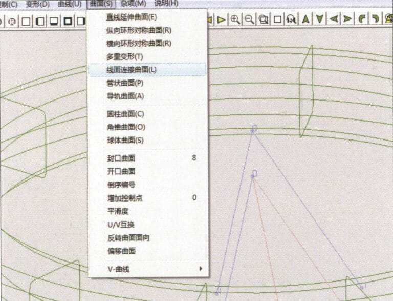
30. Select curves/surfaces in a clockwise direction to create line-surface connections, then select "Surface" > "Cap Surface" from the menu bar
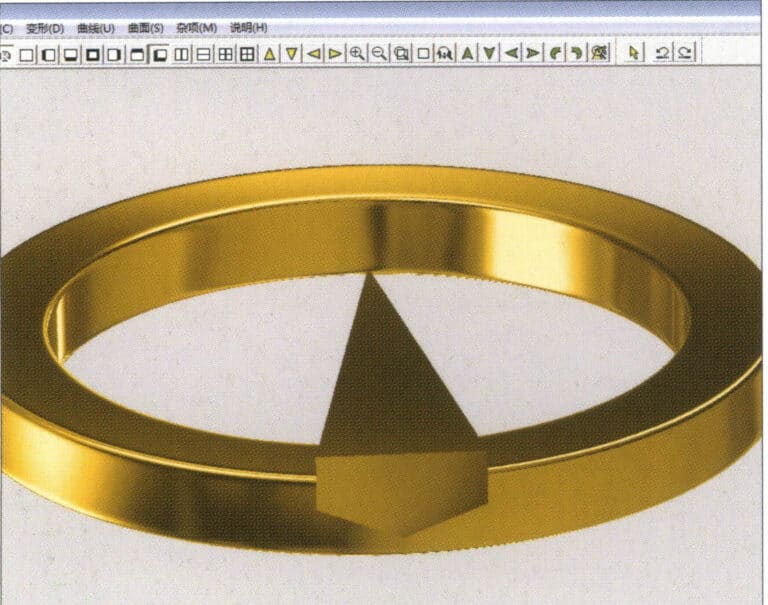
31. Select "View" > "Shadow Map" from the menu bar to inspect the shadow effects
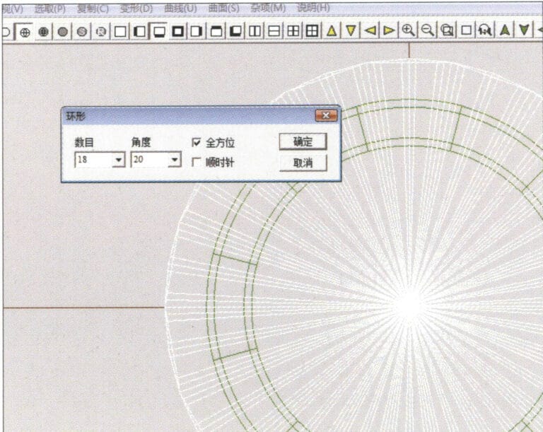
32. Select "Copy" > "Circular Copy" from the menu bar, enter the relevant values and confirm
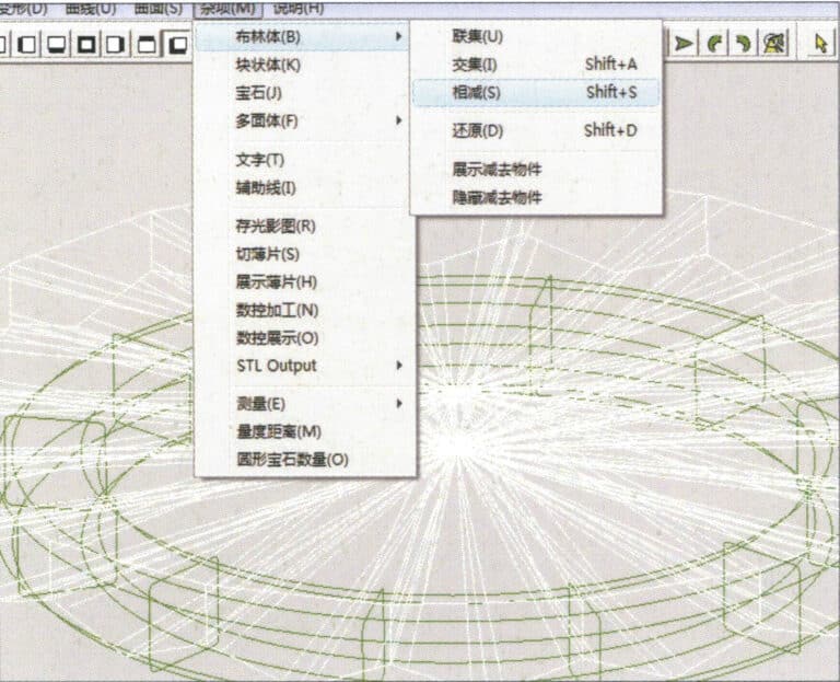
33. Select "Miscellaneous" > "Boolean" > "Subtract" from the menu bar to subtract the selected surface from the already united surface
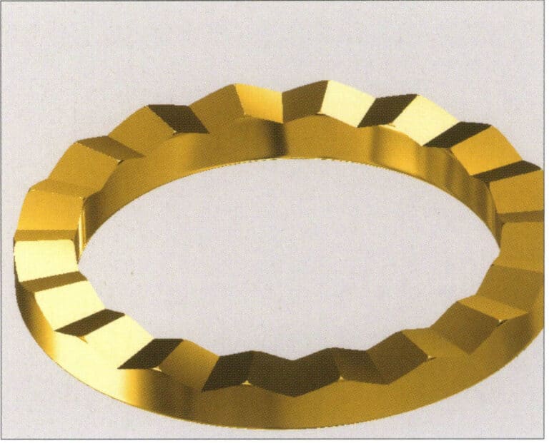
34. Select "View" > "Shadow Map" from the menu bar to inspect the shadow effects
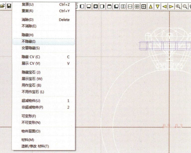
35. Select "Edit" > "Unhide" from the menu bar to display the hidden objects
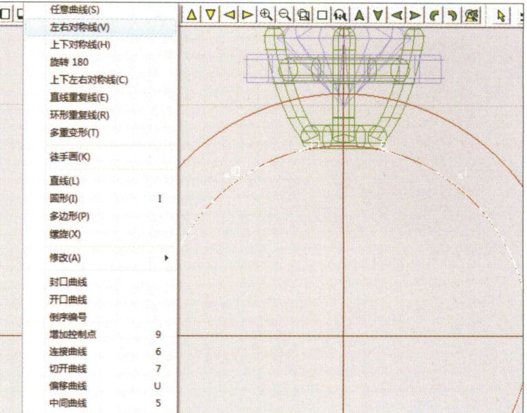
36. Select "Curve" > "Left-Right Symmetry Line" from the menu bar to draw the inner diameter of the ring wall
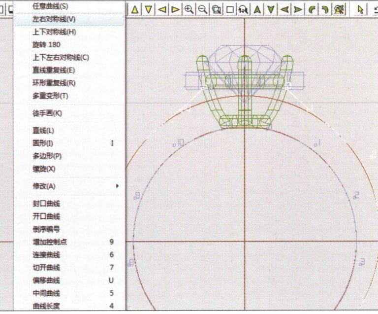
37. Select "Curve" > "Left-Right Symmetry Line" from the menu bar to draw the outer diameter of the ring wall
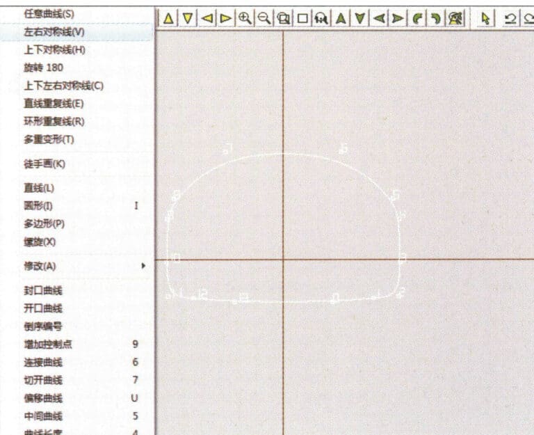
38. Select “Curve” > “Left-Right Symmetry Line” in the menu bar to draw a cutout of the ring shank
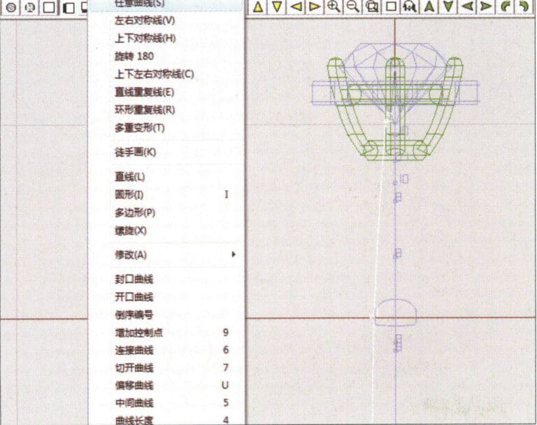
39. Select "Curve" > "Freeform Curve" from the menu bar to draw a guideline
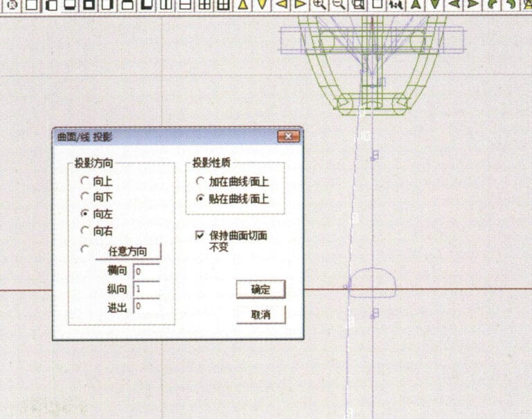
40. Select "Deformation" > "Surface/Line Projection" from the menu bar to enter the "Surface/Line Projection" dialog box, input the relevant values and confirm
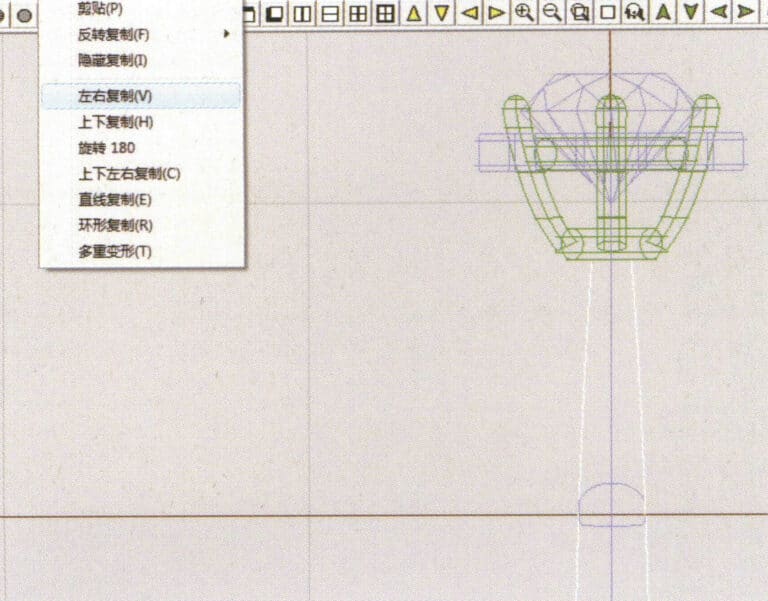
41. Select "Copy" > "Copy Left and Right" from the menu bar to copy the inner diameter of the ring shank
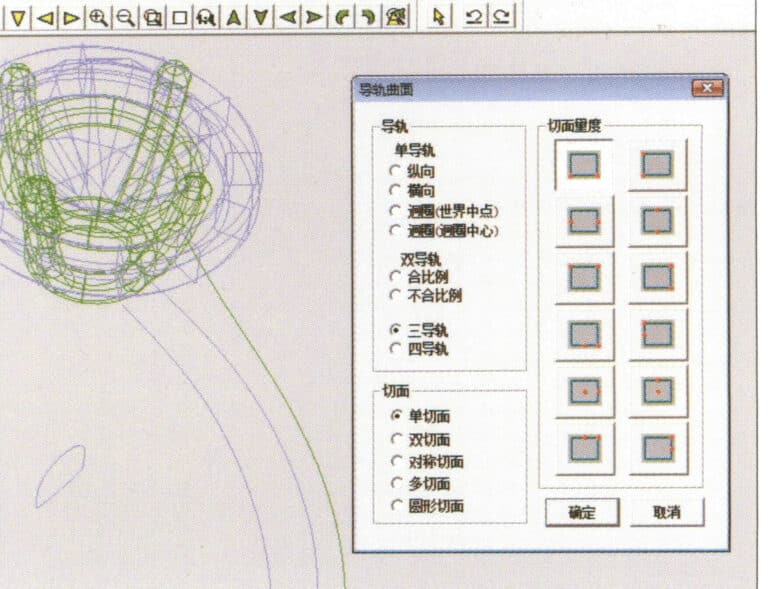
42. Select "Surface" > "Rail Surface" from the menu bar to enter the "Rail Surface" dialog box, select the relevant options and confirm
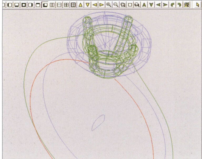
43. Wybierz krzywą jako lewą szynę prowadzącą, a następnie wybierz krzywą jako prawą szynę prowadzącą

44. Wybierz krzywą jako górną szynę prowadzącą
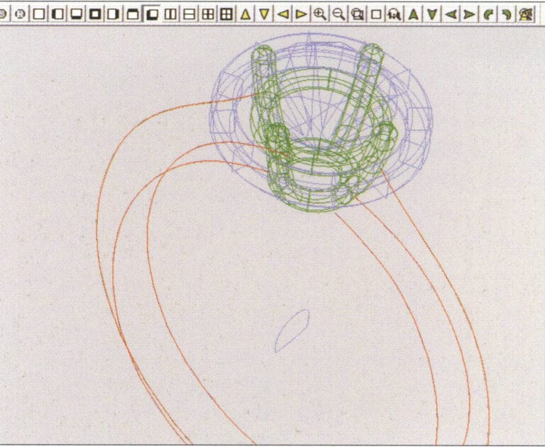
45. Wybierz krzywą jako przekrój powierzchni prowadzącej.
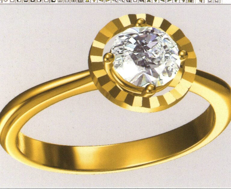
46. Select "View" > "Light and Shadow Map" from the menu bar to examine the light and shadow effects
47. Select "File" > "Save As" from the menu bar to save the file
Copywrite @ Sobling.Jewelry - Producent biżuterii na zamówienie, fabryka biżuterii OEM i ODM
2. Pierścionek z perłą

Etapy produkcji są następujące:
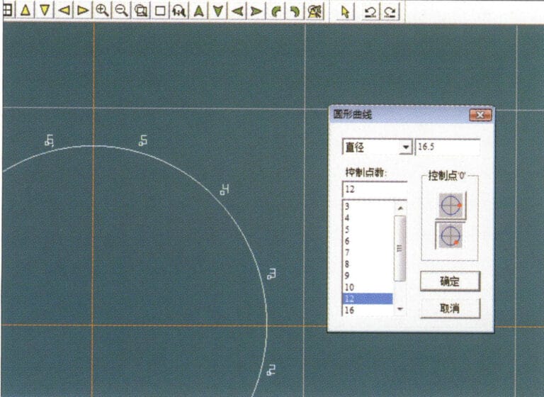
1. Create a new file in JewelCAD, select "Curve" > "Circular Curve" from the menu bar, enter the relevant values in the "Circular Curve" dialog box as the outer curve of the ring, and confirm
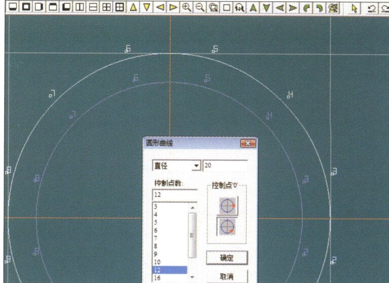
2. Select "Curve" > "Circular Curve" from the menu bar, enter the relevant values in the "Circular Curve" dialog box to set the inner curve of the ring, and confirm
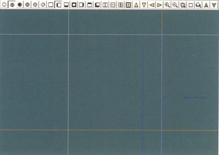
3. Select "Edit" > "Move" from the menu bar to move the selected inner curve of the ring
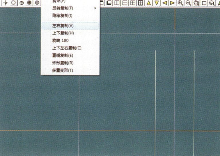
4. Select "Copy" > "Copy Left and Right" from the menu bar to copy the curve of the inner circle of the ring
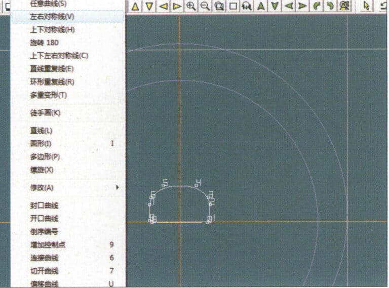
5. Select "Curve" > "Left-Right Symmetry Line" from the menu bar as the cross-section of the ring band
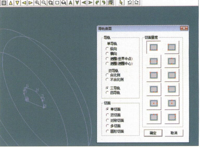
6. Select "Curved Surface" > "Guide Rail Surface" from the menu bar, enter the "Guide Rail Surface" dialog box, select the relevant options and confirm
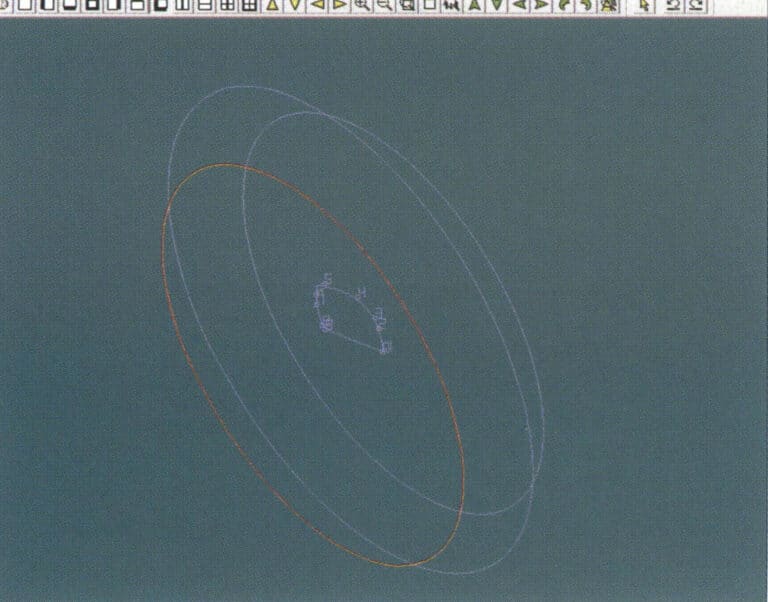
7. Wybierz krzywą jako właściwą szynę prowadzącą
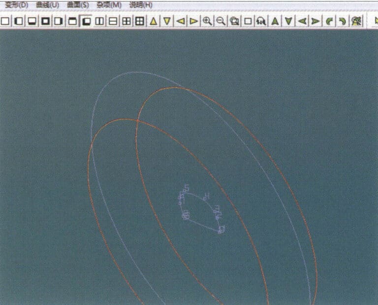
8. Wybierz krzywą jako górną szynę prowadzącą
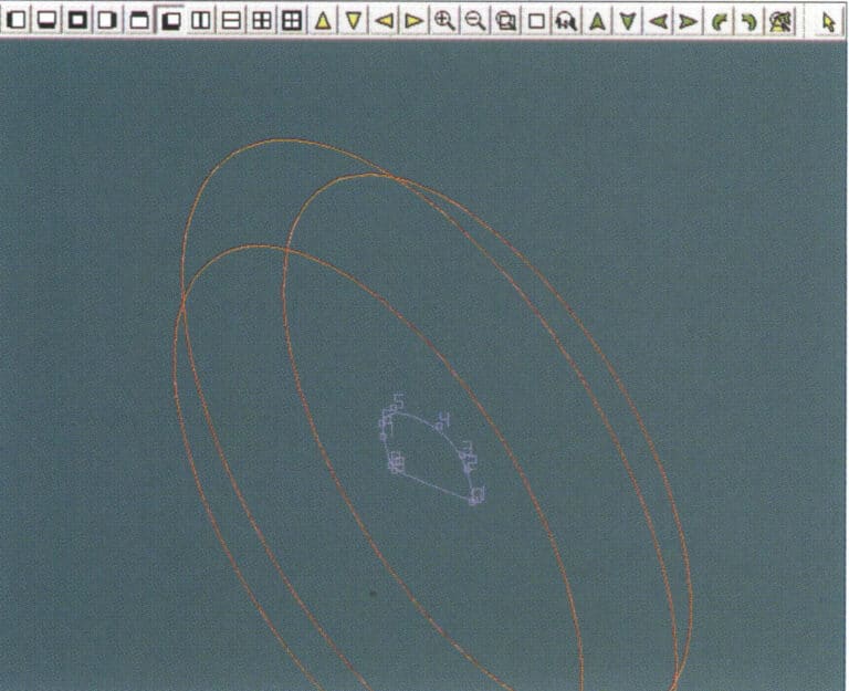
9. Wybierz przekrój poprzeczny pierścienia jako przekrój poprzeczny powierzchni krzywej prowadzącej
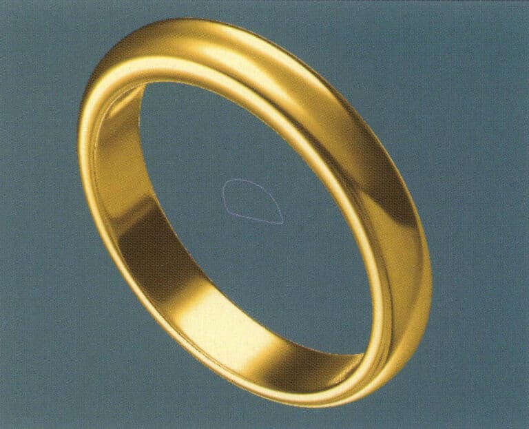
10. Select "View" > "Shadow Map" from the menu bar to inspect the shadow effects
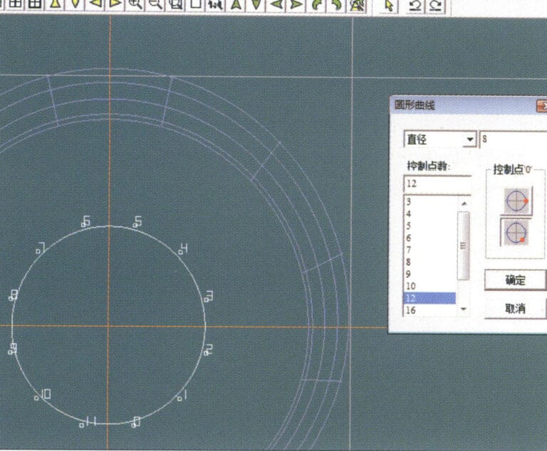
11. Select "Curve" > "Circular Curve" from the menu bar, enter the relevant values in the "Circular Curve" dialog box as auxiliary lines, and confirm
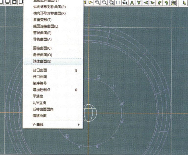
12. Select "Surface" > "Spherical Surface" from the menu bar
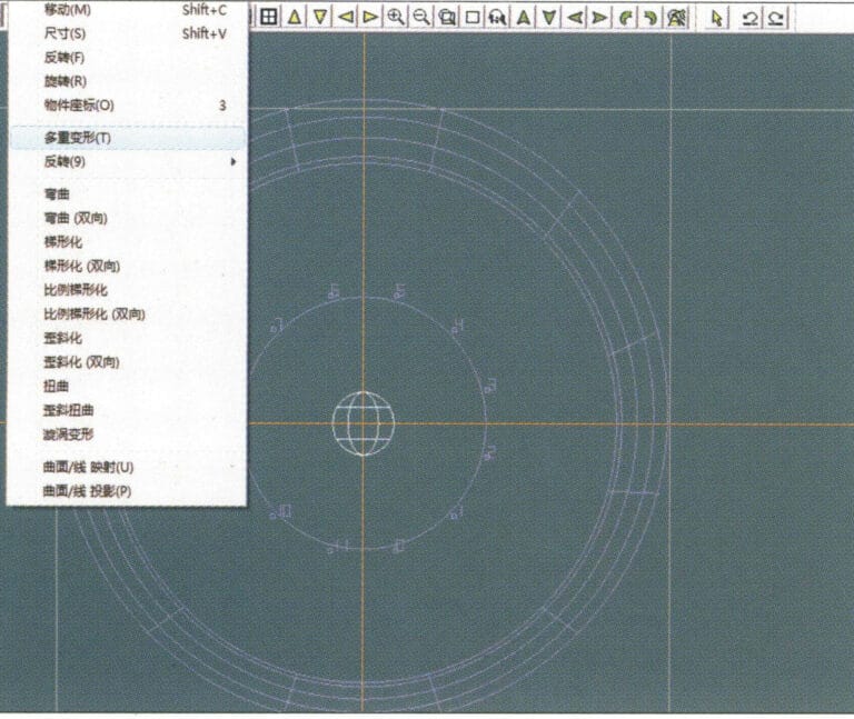
13. Select "Deformation" > "Multiple Deformation" from the menu bar to enlarge the sphere
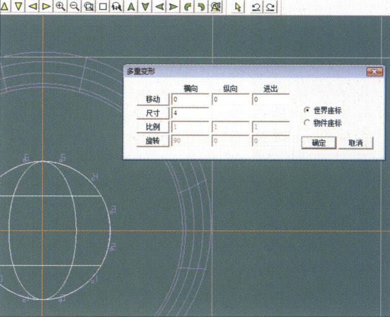
14. Przejdź do okna dialogowego "Deformacja wielokrotna", wprowadź odpowiednie wartości, aby powiększyć kulę do szerokości linii pomocniczych i potwierdź.
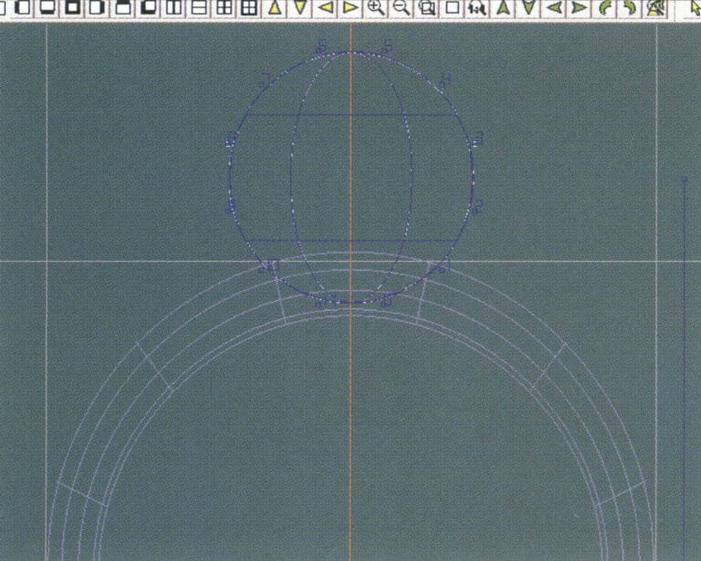
15. Select "Edit" > "Move" from the menu bar to move both the sphere and the auxiliary line simultaneously
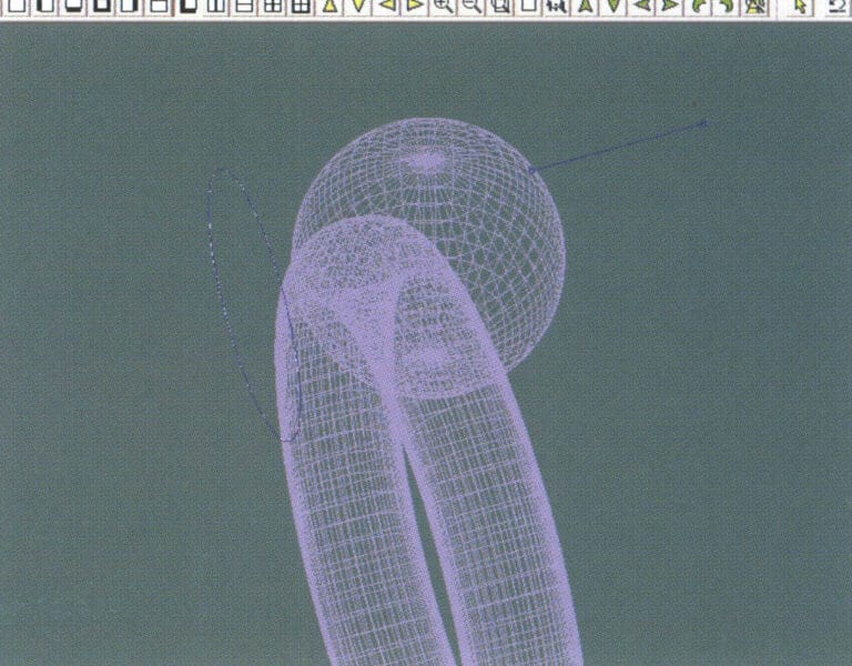
16. Select "Edit" > "Move" from the menu bar to remove the guidelines
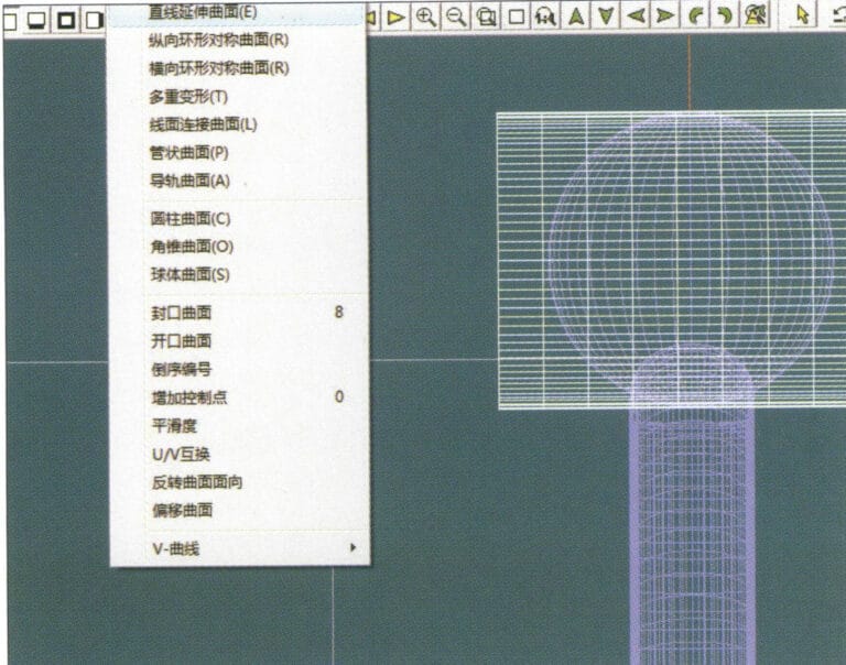
17. Select "Surface" > "Straight Line Extend Surface" from the menu bar to extend the auxiliary line into an auxiliary surface
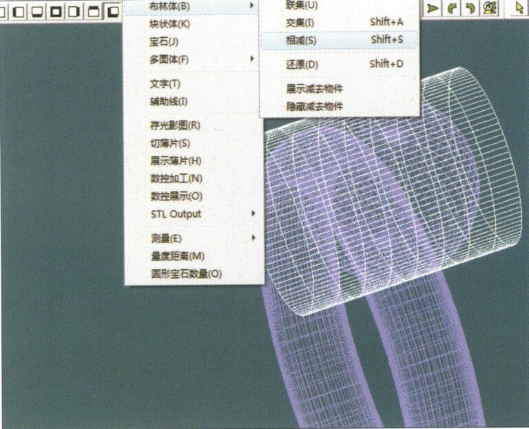
18. Select "Miscellaneous" > "Boolean" > "Subtract" from the menu bar to subtract the corresponding parts of the auxiliary surface ring
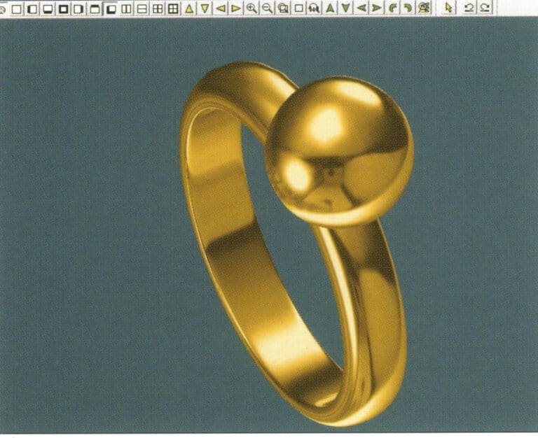
19. Select "View" > "Shadow Map" from the menu bar to inspect the shadow effects
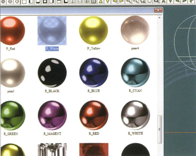
20. Select the sphere, go to the menu bar and choose "Edit" > "Materials", enter the "Materials" dialog box, select the white pearl material and confirm
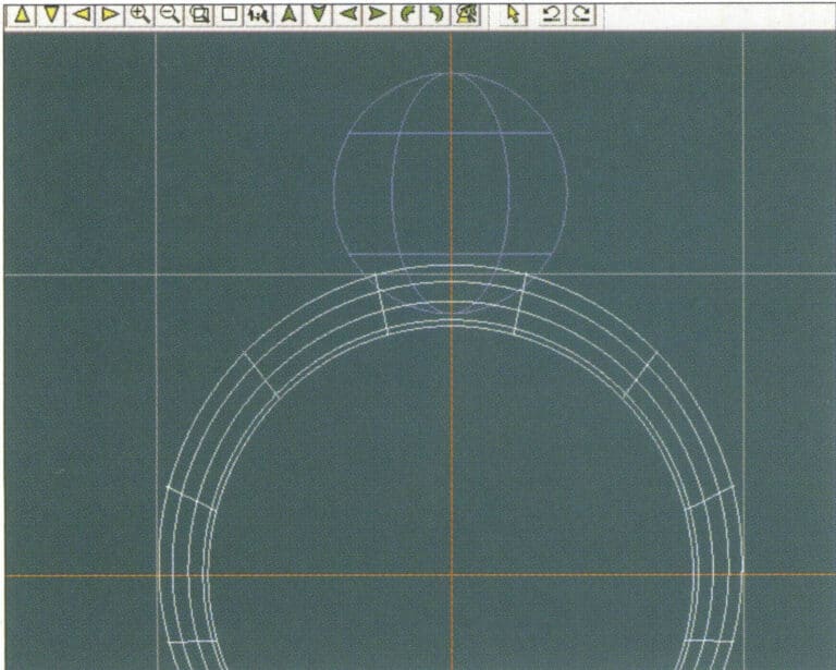
21. Select the ring band, then choose "Edit" > "Materials" from the menu bar
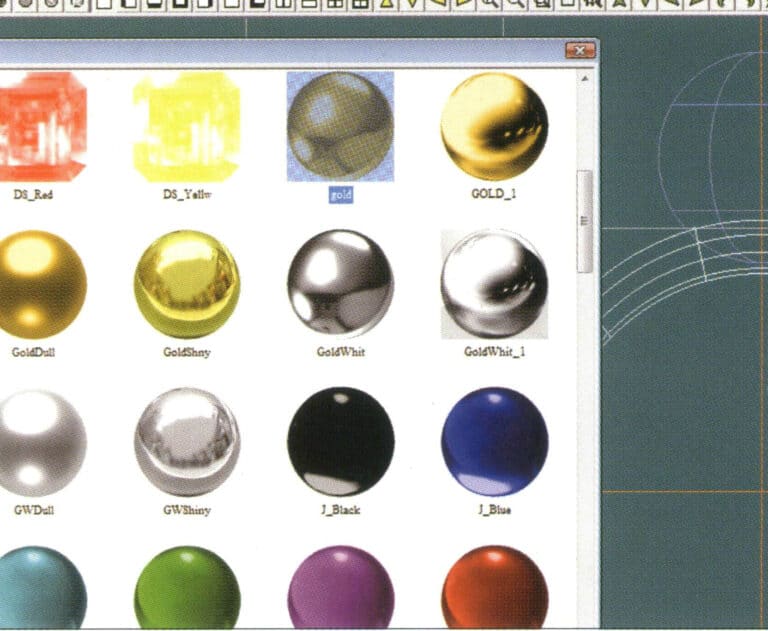
22. Przejdź do okna dialogowego "Materiały", wybierz odpowiedni materiał i potwierdź.
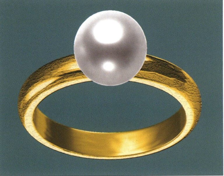
23. Select "View" > "Shadow Map" from the menu bar to examine the light and shadow effects
24. Select "File" > "Save As" from the menu bar to save the file
3. Wisiorek z czarnego złota z diamentowymi akcentami

Etapy produkcji są następujące:
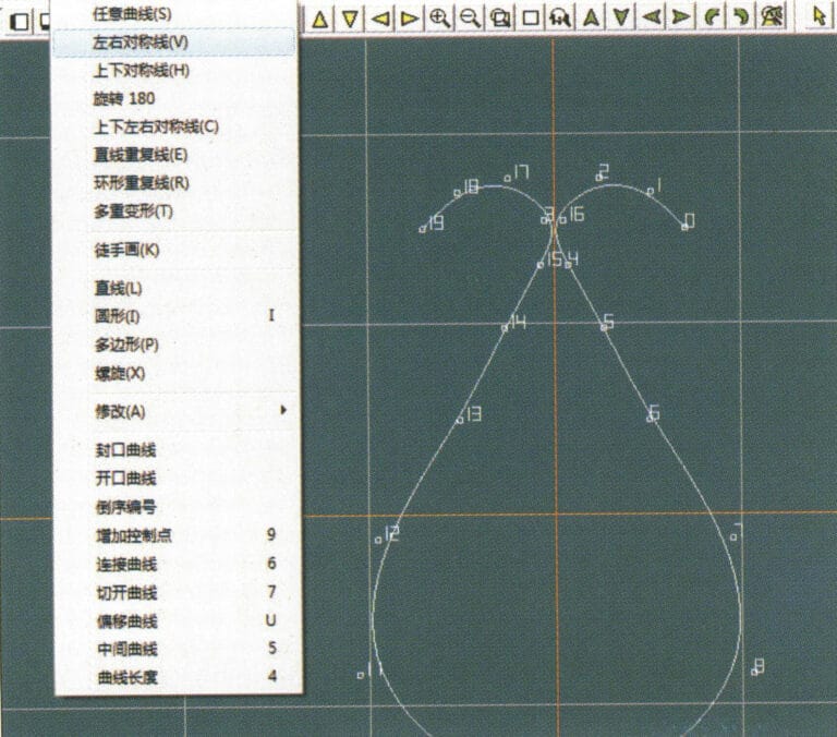
1. Create a new file in JewelCAD, select "Curve" > "Left-Right Symmetrical Line" from the menu bar, and draw the inner contour line of the pendant
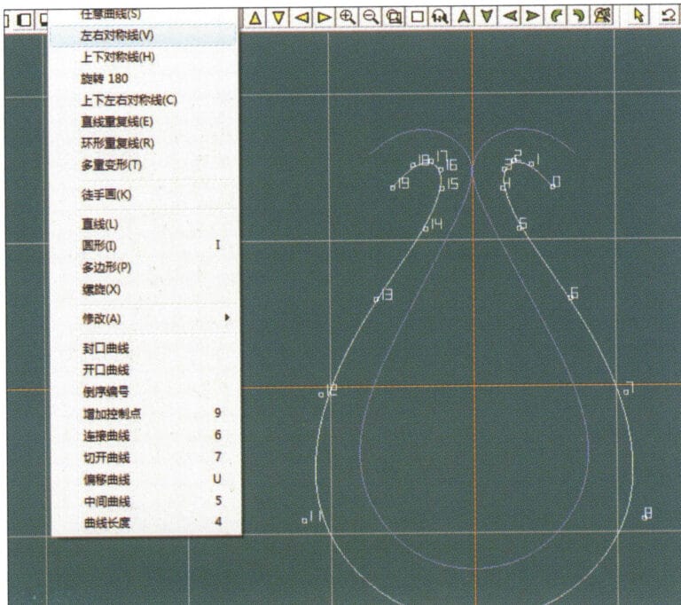
2. Select "Curve" > "Left-Right Symmetrical Line" from the menu bar to draw the outer contour line of the pendant (note that the control points of the inner contour line and the outer contour line should have the same direction and quantity).
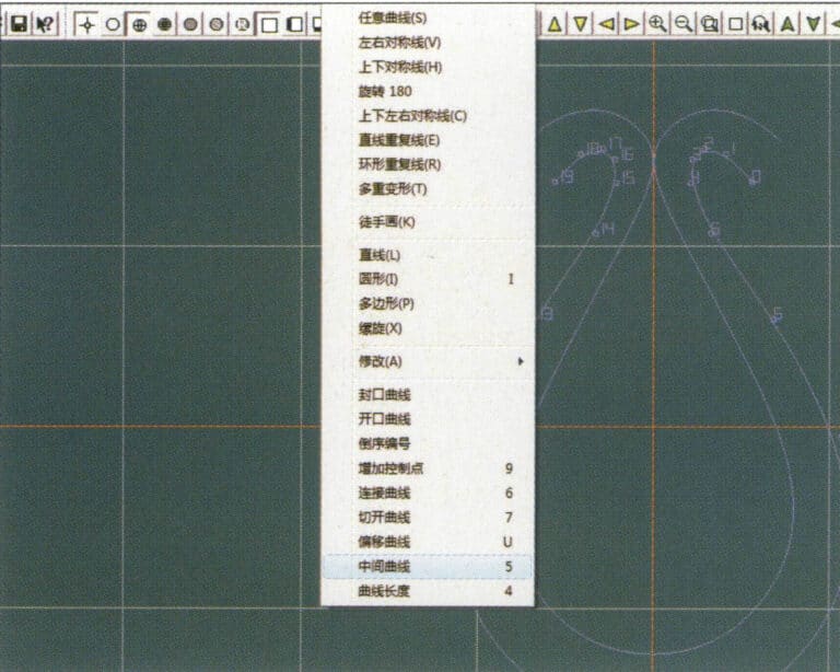
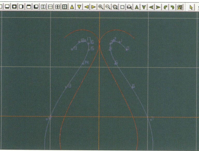
3. Select "Curve" > "Middle Curve" from the menu bar
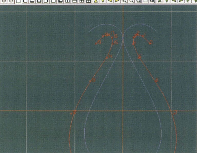
4. Wybierz dwie krzywe, aby utworzyć krzywą środkową. Najpierw wybierz zewnętrzną linię konturu
5. Wybierz dwie krzywe, aby utworzyć środkową krzywą, a następnie wybierz wewnętrzną linię konturu
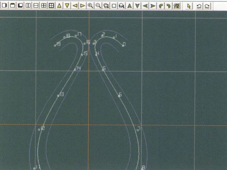
6. Wyświetl już utworzone krzywe pośrednie
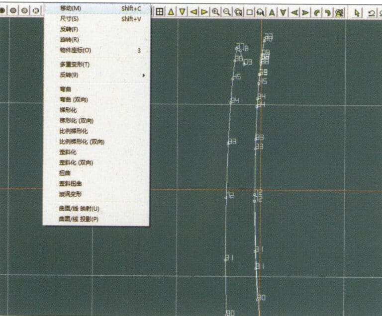
7. Select "Deformation" > "Move" from the menu bar to move the CV and the CV of the contour line
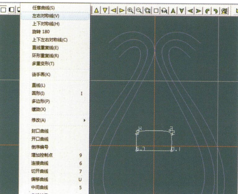
8. Select "Curve" > "Left-Right Symmetry Line" from the menu bar to create a cross-section
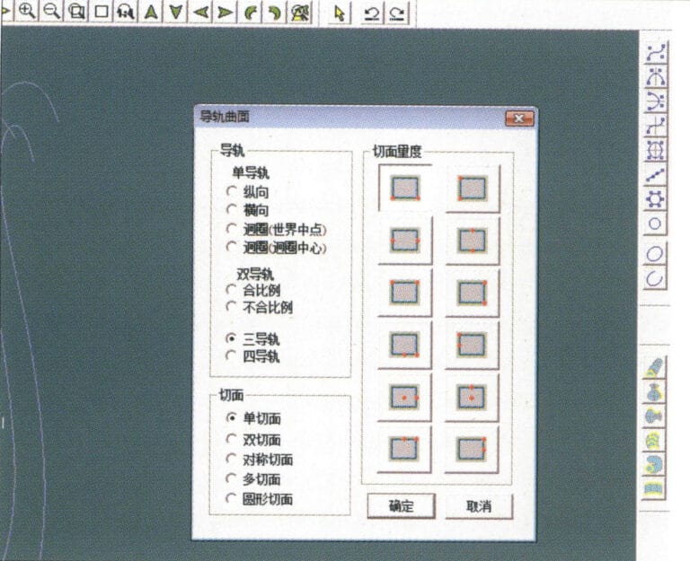
9. Select "Surface" > "Rail Surface" from the menu bar, enter the "Rail Surface" dialog box to select the relevant options, and confirm; select a curve as the left curve, starting from the left curve in a clockwise direction, left-click on the curve as the rail, and then select another curve as the section of the rail surface
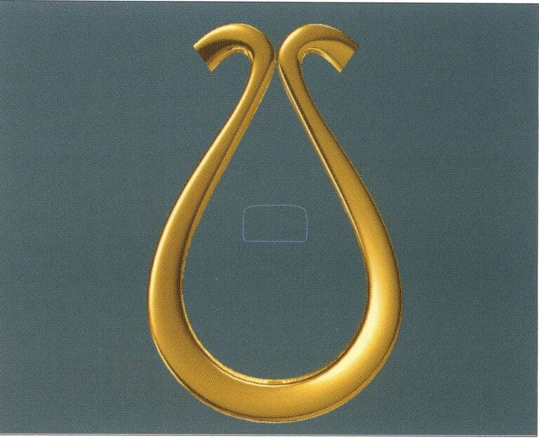
10. Select "View" > "Shadow Map" from the menu bar to inspect the shadow effects
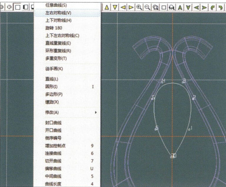
11. Select "Curve" > "Left-Right Symmetry Line" from the menu bar to draw the outer contour line of the seed-shaped toggle
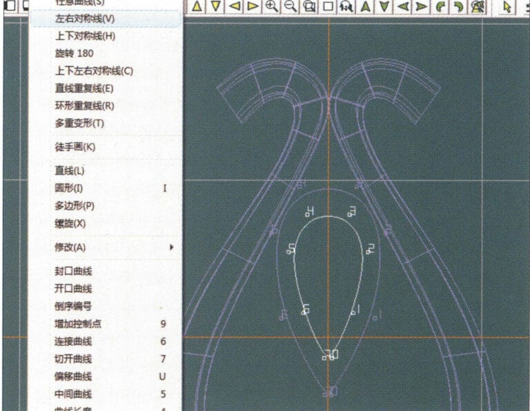
12. Select "Curve" > "Left-Right Symmetry Line" from the menu bar to draw the inner contour line of the seed-shaped toggle
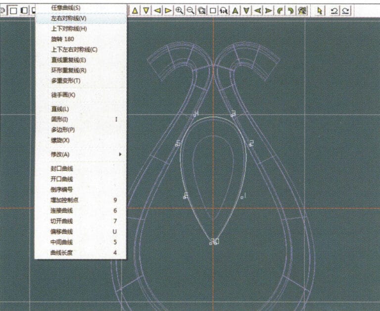
13. Select "Curve" > "Left-Right Symmetry Line" from the menu bar, and draw the lower dark line of the center of the seed-shaped toggle
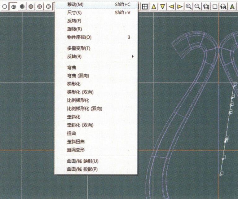
14. Select "Deformation" > "Move" from the menu bar to move the seed-shaped toggle CV
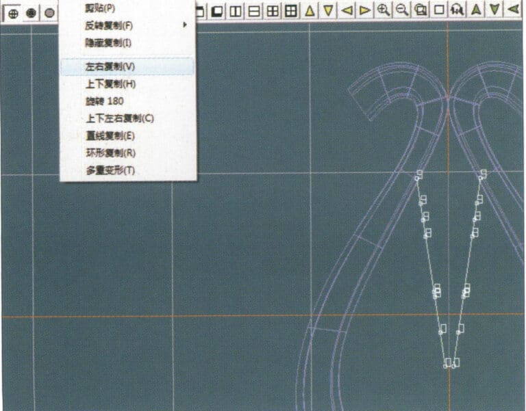
15. Select "Copy" > "Copy Left and Right" from the menu bar to copy the curve of the seed-shaped toggle
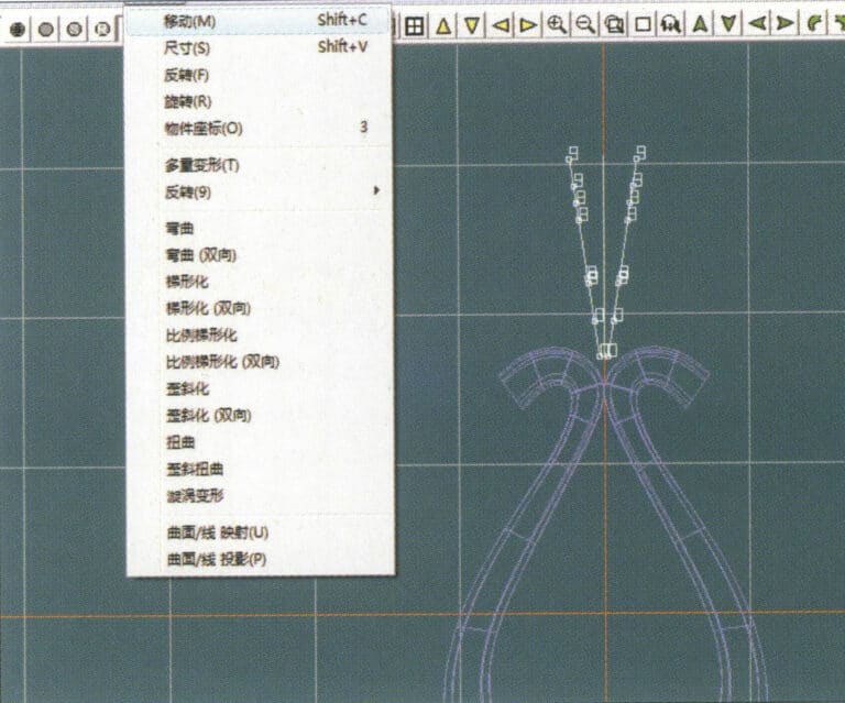
16. Select "Deformation" > "Move" from the menu bar to move the melon seed buckle curve
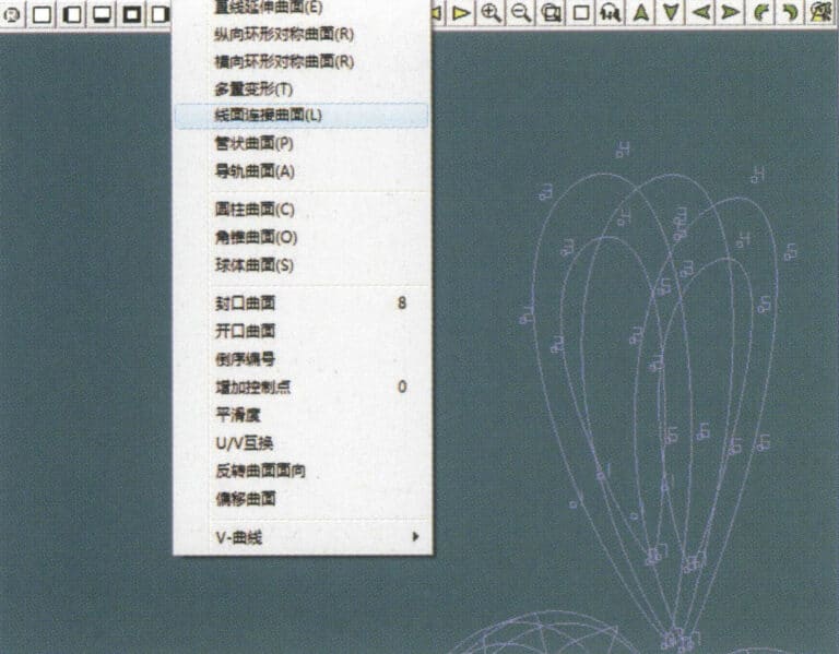
17. Select "Surface" > "Line-Surface Connection Surface" from the menu bar, and select the curve/surface in a clockwise direction to create a line-surface connection surface, then select "Curve" > "Closed Surface" from the menu bar
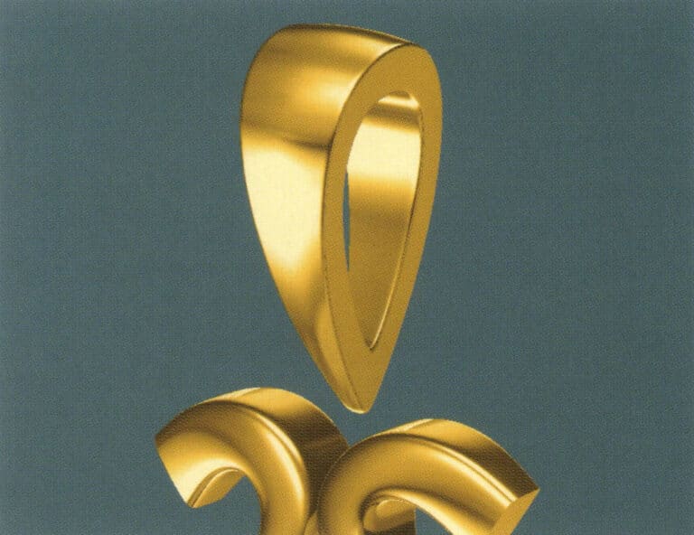
18. Select "View" > "Shadow Map" from the menu bar to examine the shadow effects
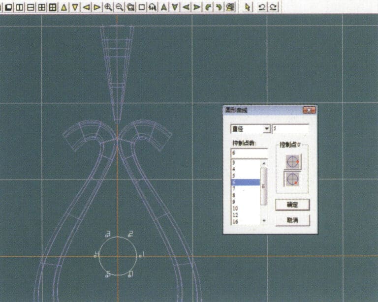
19. Select "Curve" > "Circular Curve" from the menu bar, enter the relevant values and confirm

20. Select "Surface" > "Tubular Surface" from the menu bar
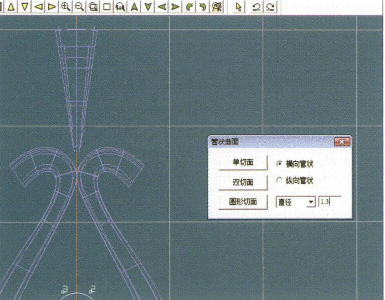
21. Wejdź do okna dialogowego "Tubular Surface", wprowadź odpowiednie wartości, kliknij na okrągły przekrój i potwierdź.
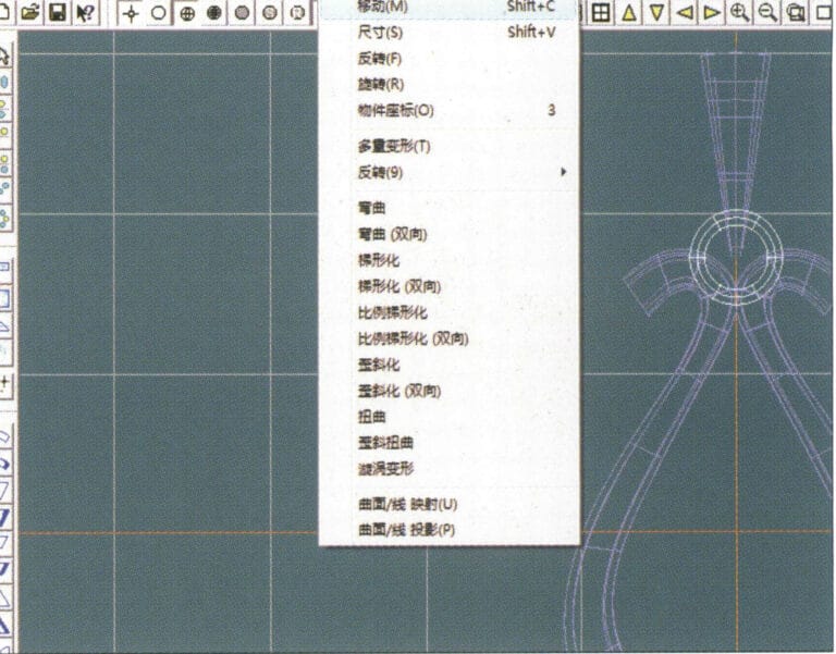
22. Select "Deformation" > "Move" from the menu bar to move the ring buckle

23. Select "File" > "Insert File" from the menu bar
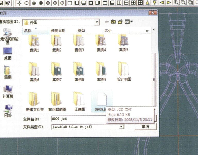
24. Przejdź do okna dialogowego "Wstaw plik", wybierz żądany dokument i potwierdź.
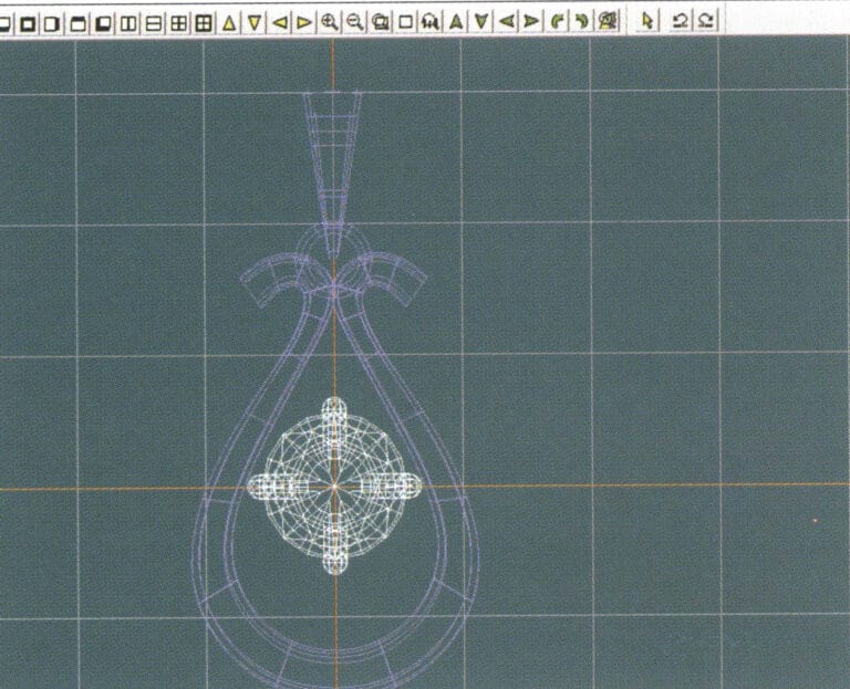
25. Zobacz wstawiony plik - Gemstone
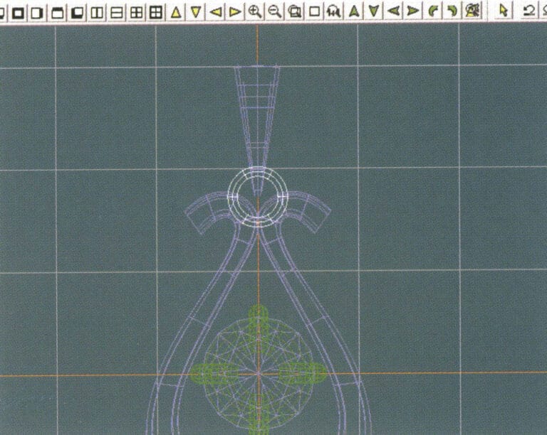
26. Select "Copy" > "Copy Up and Down" from the menu bar to copy the selected toggle
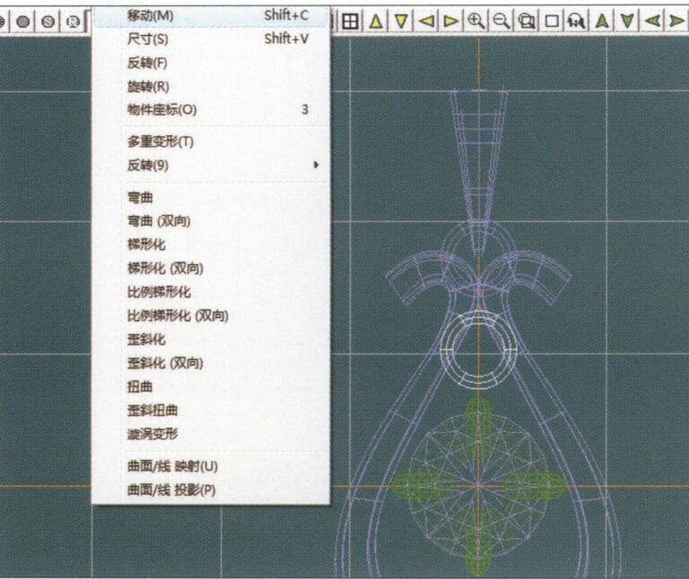
27. Select "Deformation" > "Move" from the menu bar to move the horizontal ring toggle
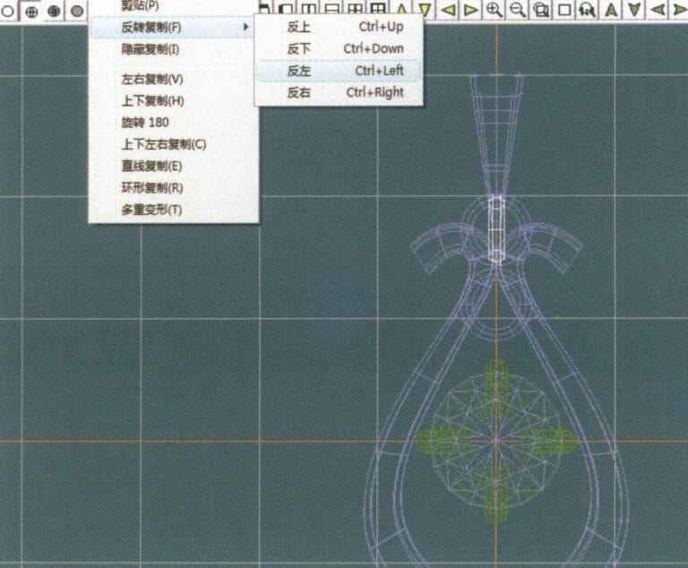
28. Select "Copy" > "Reverse Copy" > "Reverse Left" from the menu bar to create a vertical ring toggle
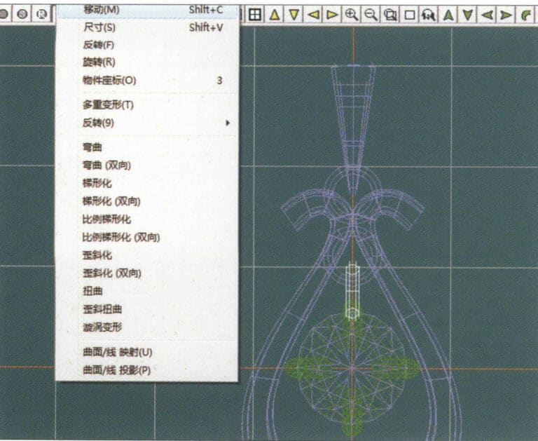
29. Select "Deformation" > "Move" from the menu bar to move the horizontal ring toggle
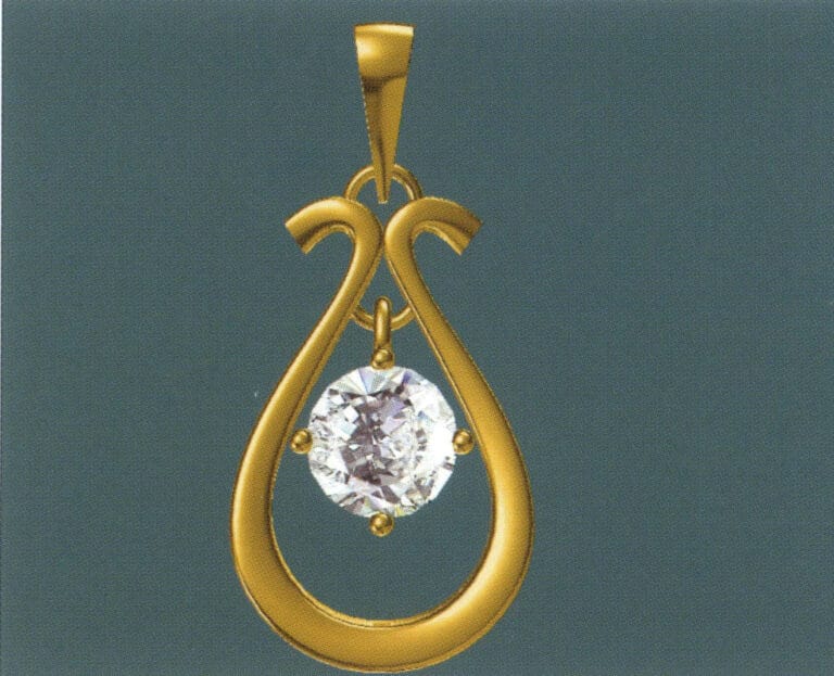
30. Select "View" > "Shadow Map" from the menu bar to examine the light and shadow effects
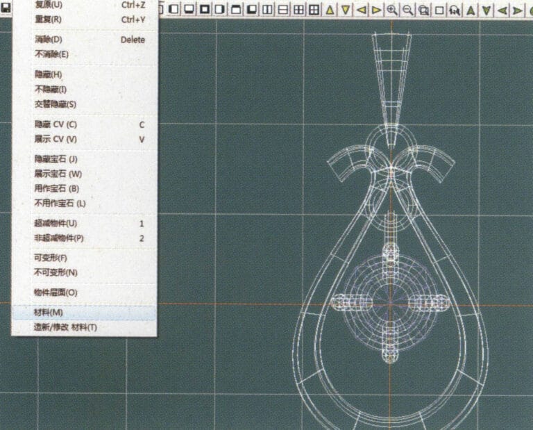
31. Select "Edit" > "Materials" from the menu bar to modify the materials of the selected object
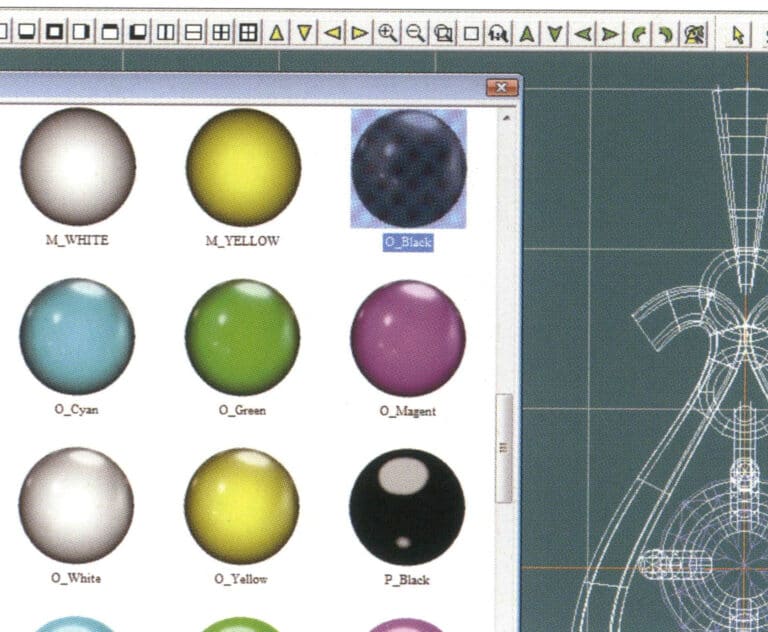
32. Przejdź do okna dialogowego "Materiały", wybierz czarne złoto i potwierdź.
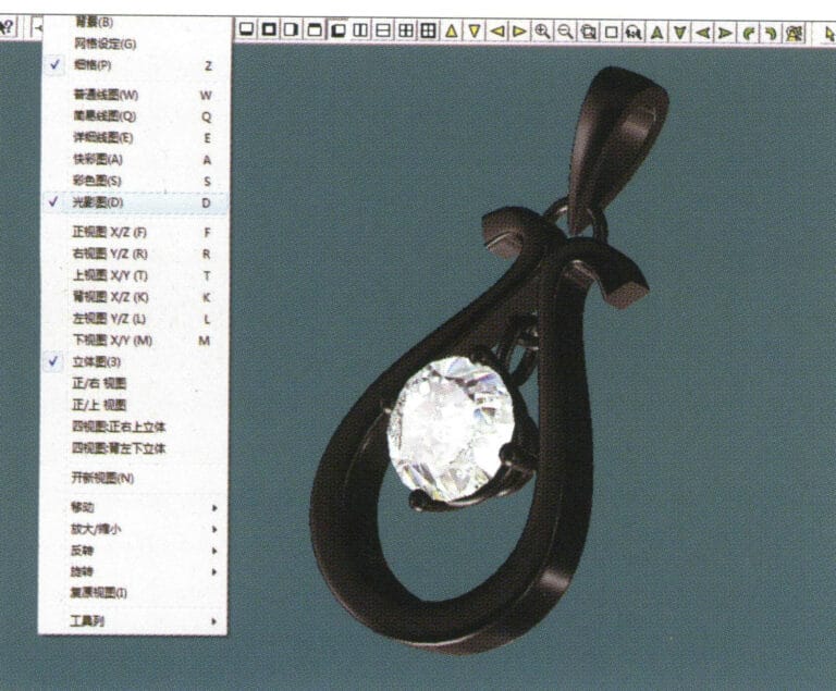
33. Select "View" > "Shadow Map" from the menu bar to inspect the shadow effects
34. Select "File" > "Save As" from the menu bar to save the file
4. Rubinowy wisiorek
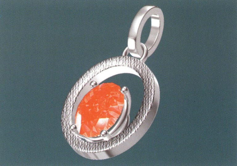
Etapy produkcji są następujące:
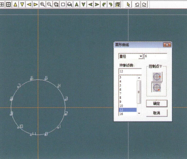
1. Create a new file in JewelCAD, select "Curve" > "Circular Curve" from the menu bar, enter the relevant values in the "Circular Curve" dialog box as the inner auxiliary line, and confirm

2. Select "Curve" > "Circular Curve" from the menu bar, enter the relevant values in the "Circular Curve" dialog box as the external auxiliary line, and confirm
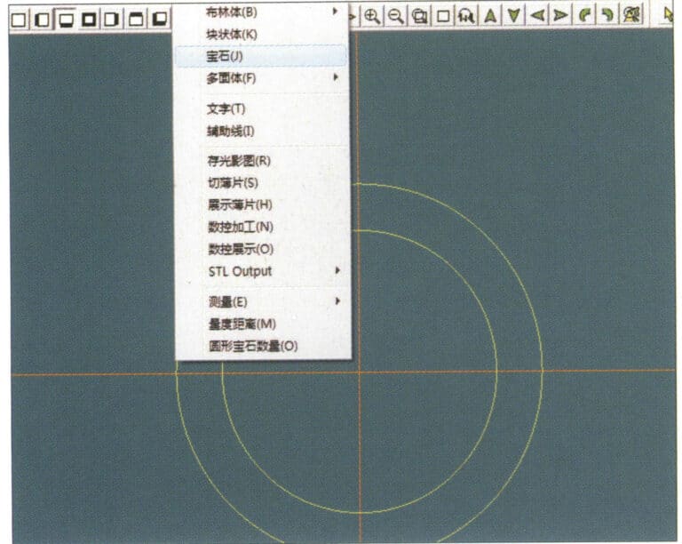
3. Select "Miscellaneous" > "Gemstones" from the menu bar
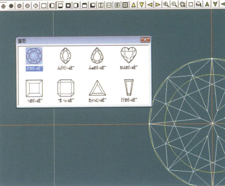
4. Przejdź do okna dialogowego "Gem", wybierz odpowiednie klejnoty i potwierdź.
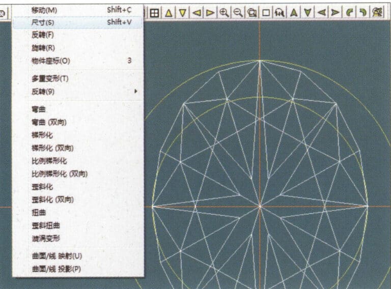
5. Select "Deformation" > "Size" from the menu bar to change the round gemstone into an oval gemstone
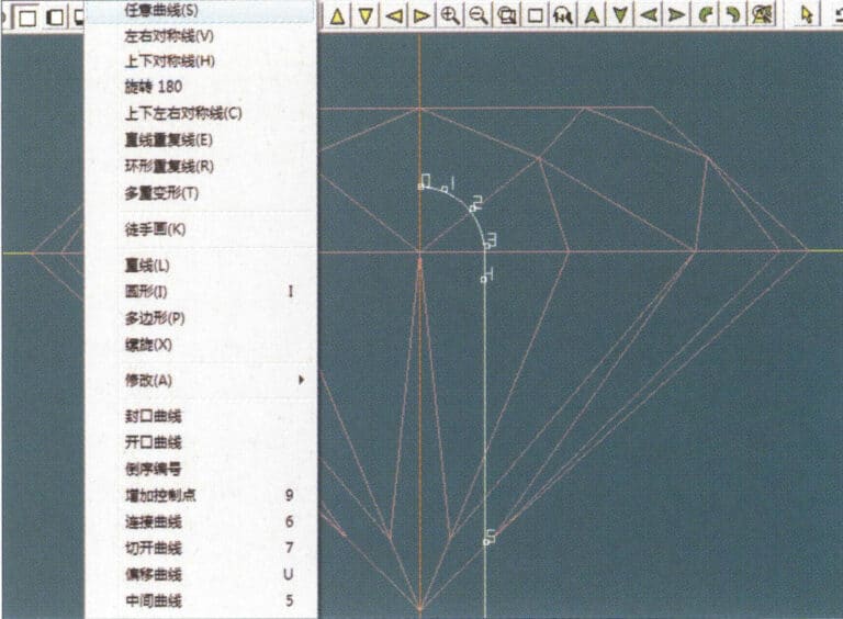
6. Select "Curve" > "Freeform Curve" from the menu bar to draw a claw-shaped guideline
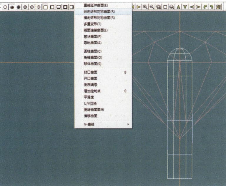
7. Select "Surface" > "Longitudinal Circular Symmetrical Surface" from the menu bar, and draw a claw shape
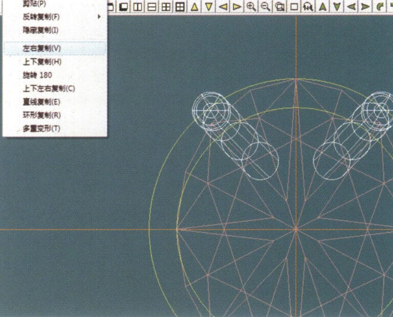
8. Select "Copy" > "Copy Left and Right" from the menu bar to copy the claw shape
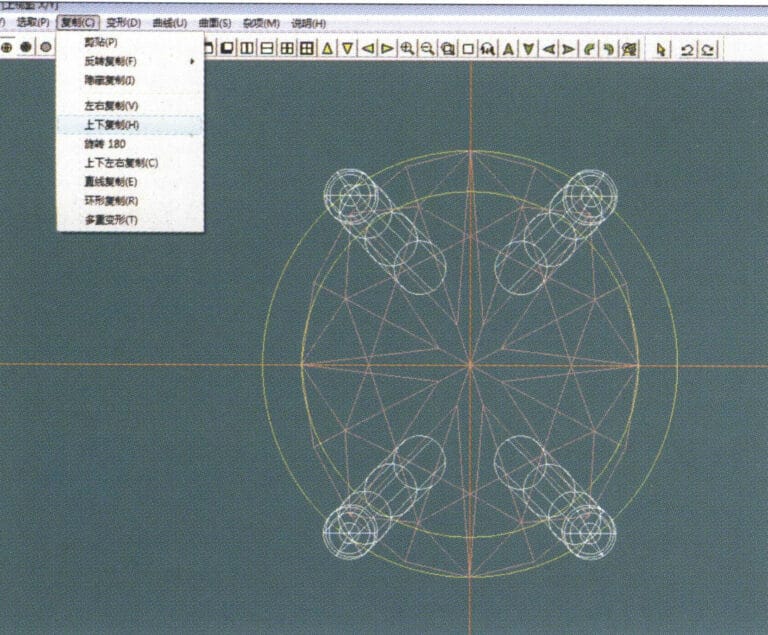
9. Select "Copy" > "Copy Up and Down" from the menu bar to copy the claw shape again
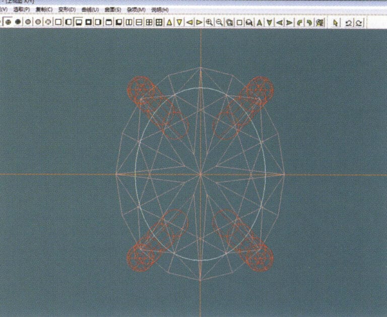
10. Select "Deformation" > "Size" from the menu bar to change the circular guideline to an elliptical guideline
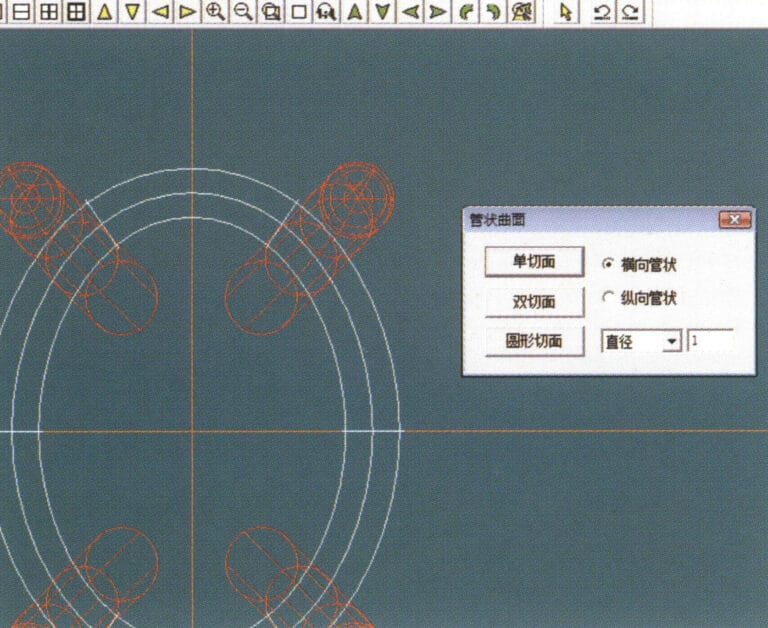
11. Select "Curved Surface" > "Tubular Surface" from the menu bar, enter the relevant values in the "Tubular Surface" dialog box and confirm
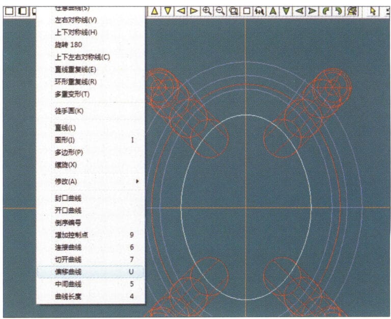
12. Select "Curve" > "Offset Curve" from the menu bar
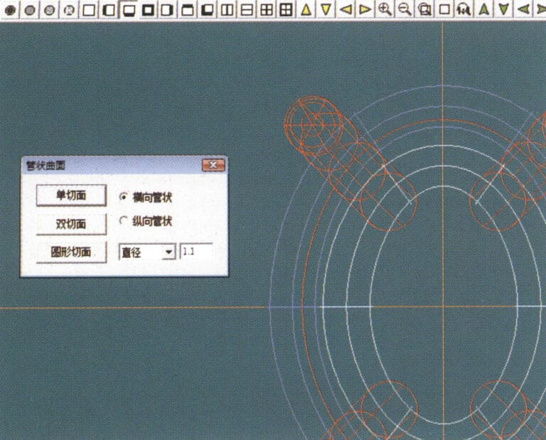
13. Select "Surface" > "Tubular Surface" from the menu bar, enter the relevant values and confirm
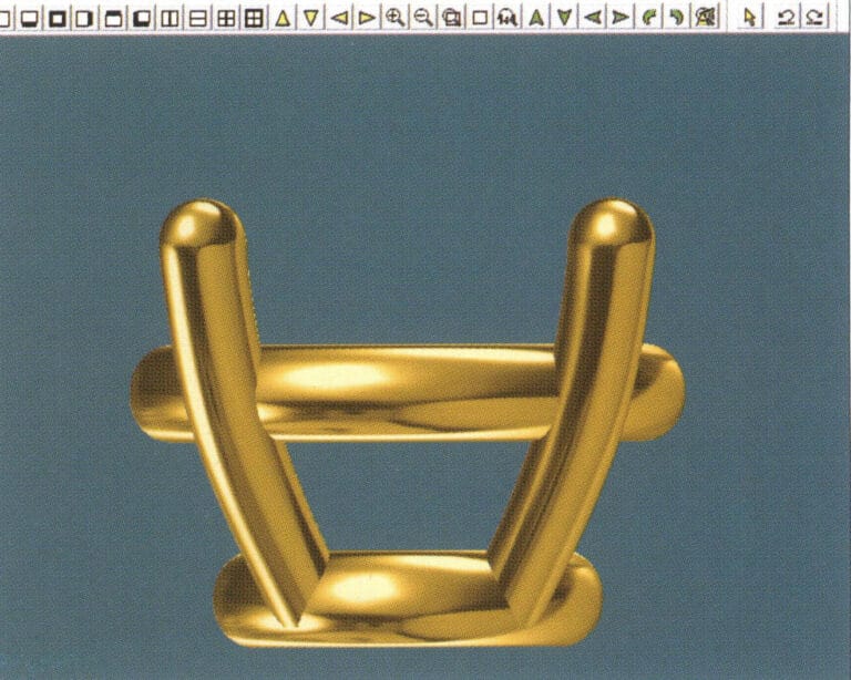
14. Select "View" > "Shadow Map" from the menu bar to examine the shadow effects and inspect the setting
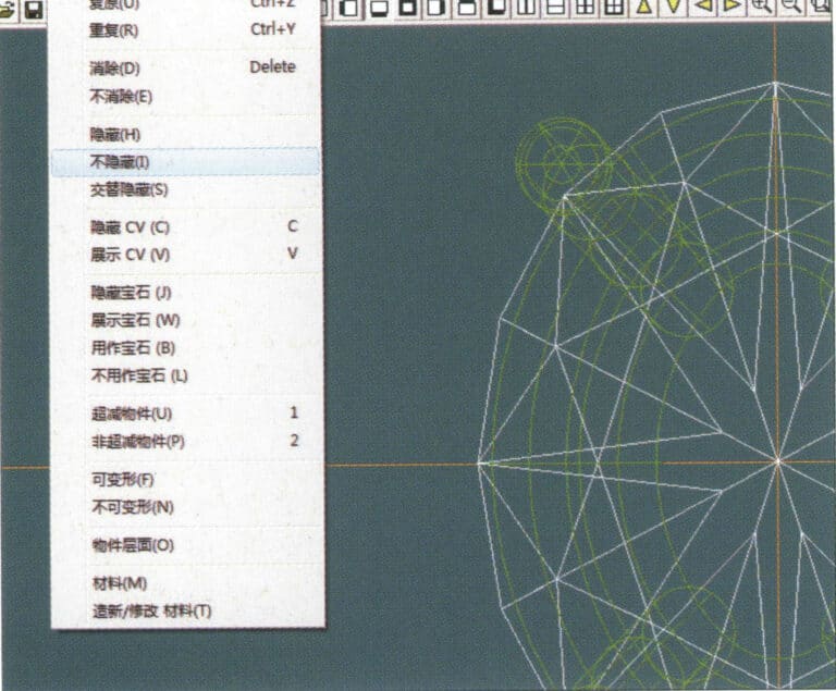
15. Select "Edit" > "Unhide" from the menu bar to display the hidden gems
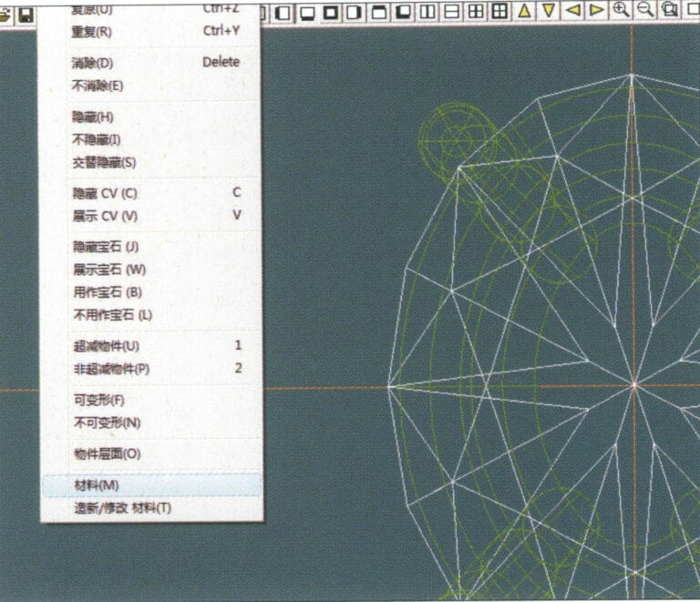
16. Select "Edit" > "Materials" from the menu bar
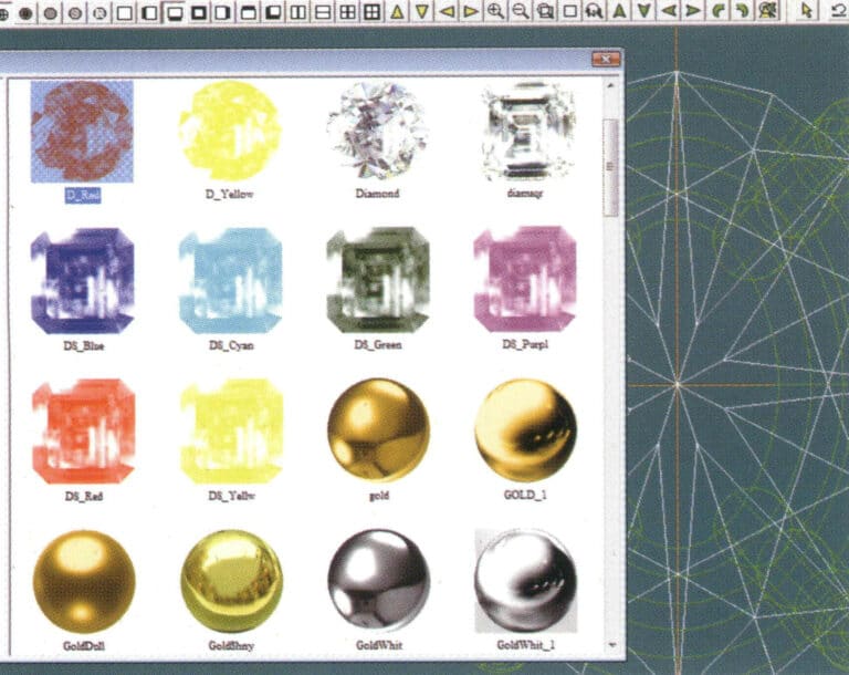
17. Przejdź do okna dialogowego "Materiały", wybierz ruby i potwierdź.
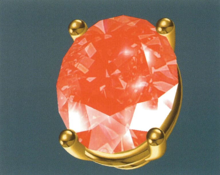
18. Select "View" > "Shadow Map" from the menu bar to examine the shadow effects
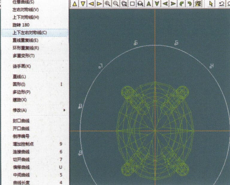
19. Select "Curve" > "Vertical and Horizontal Symmetry Line" from the menu bar as the auxiliary line for the outer circle
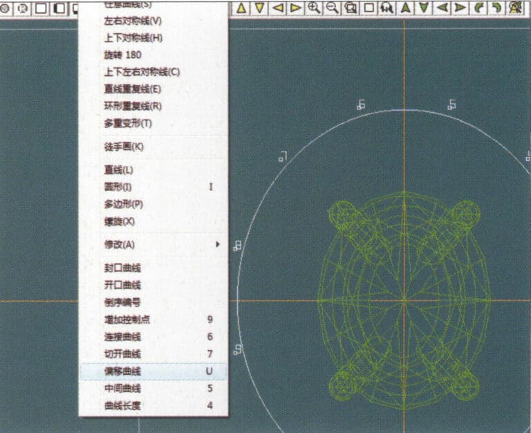
20. Select "Curve" > "Offset Curve" from the menu bar

21. Przejdź do okna dialogowego "Krzywa przesunięcia", wprowadź odpowiednie wartości jako linie pomocnicze dla wewnętrznego okręgu i potwierdź.
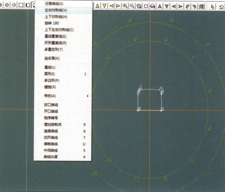
22. Select "Curve" > "Left-Right Symmetrical Line" from the menu bar as the cross-section of the coil
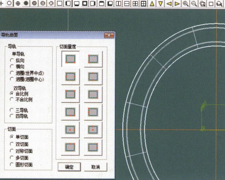
23. Select "Curved Surface" > "Rail Surface" from the menu bar to enter the "Rail Surface" dialog box, select the relevant options and confirm
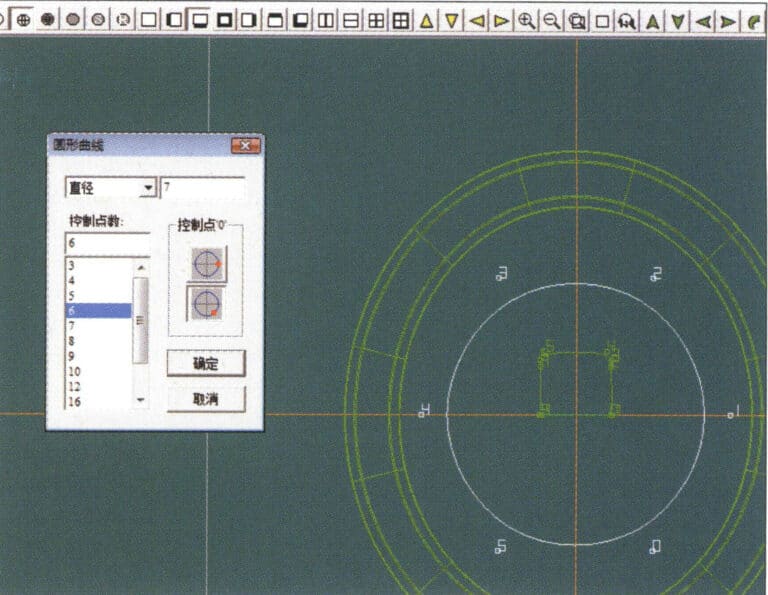
24. Select "Curve" > "Circular Curve" from the menu bar, enter the relevant values in the "Circular Curve" dialog box, and confirm; left-click on one curve as the left guide curve, click on another curve as the right guide rail, and then select the coil cross-section as the cross-section of the guide rail surface; once completed, it serves as the auxiliary line for the outer circle of the chain threading position
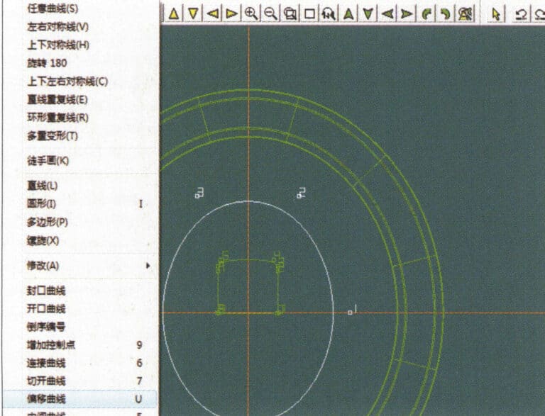
25. After completing the outer auxiliary lines for the chain position, select "Curve" > "Offset Curve" from the menu bar
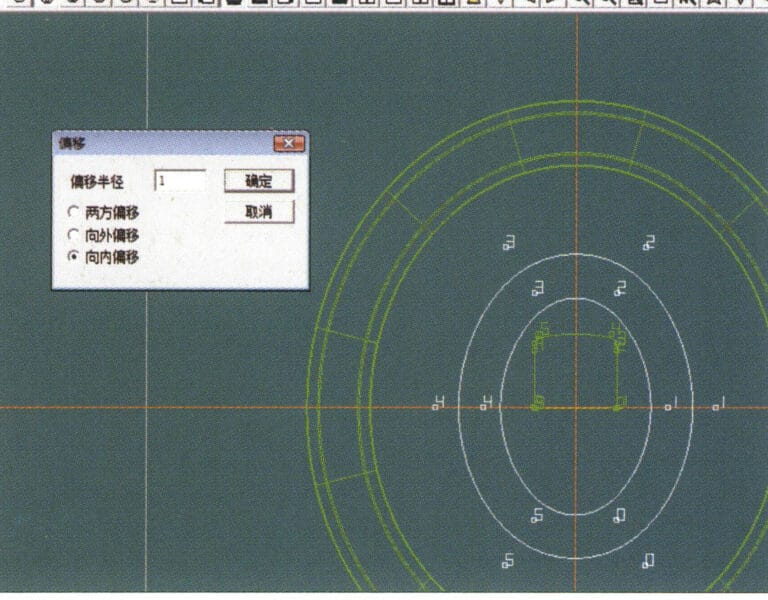
26. Przejdź do okna dialogowego "Offset Curve" (Krzywa przesunięcia), wprowadź odpowiednie wartości i potwierdź.
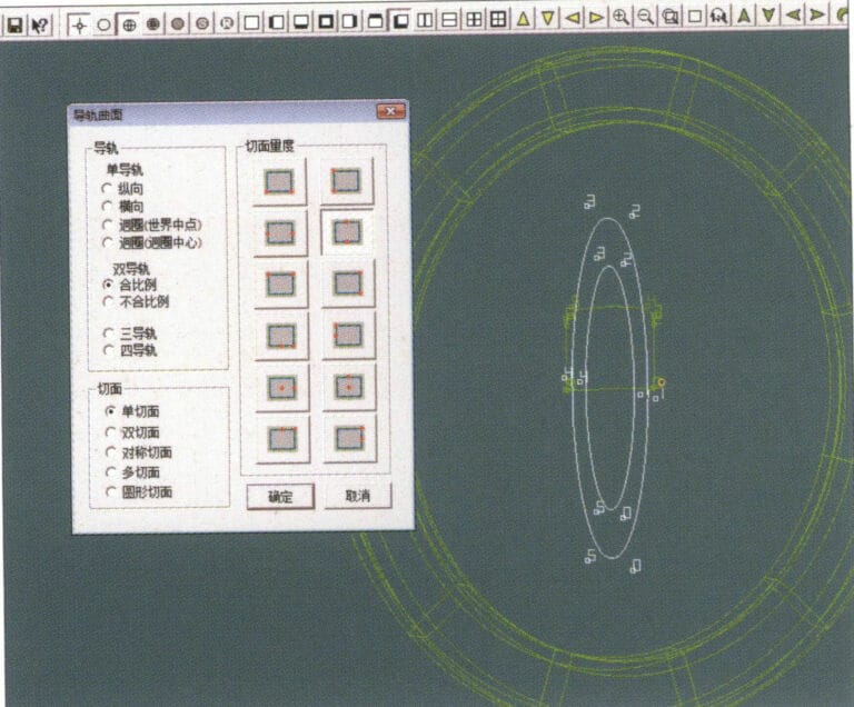
27. Select "Surface" > "Rail Surface" from the menu bar to enter the "Rail Surface" dialog box, select the relevant options and confirm, left-click on a curve to set it as the left rail curve, click on another curve to set it as the right rail, and then select the coil cross-section as the cross-section of the rail surface
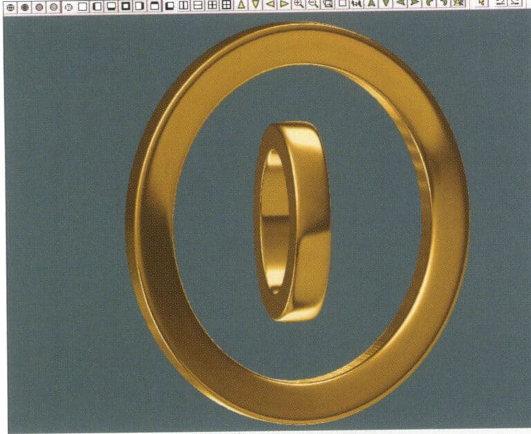
28. Select "View" > "Shadow Map" from the menu bar to inspect the shadow effects
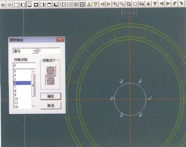
29. Select "Curve" > "Circular Curve" from the menu bar, enter the relevant values and confirm
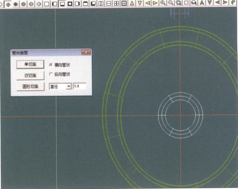
30. Select "Curved Surface" > "Tubular Surface" from the menu bar, enter the relevant values and confirm
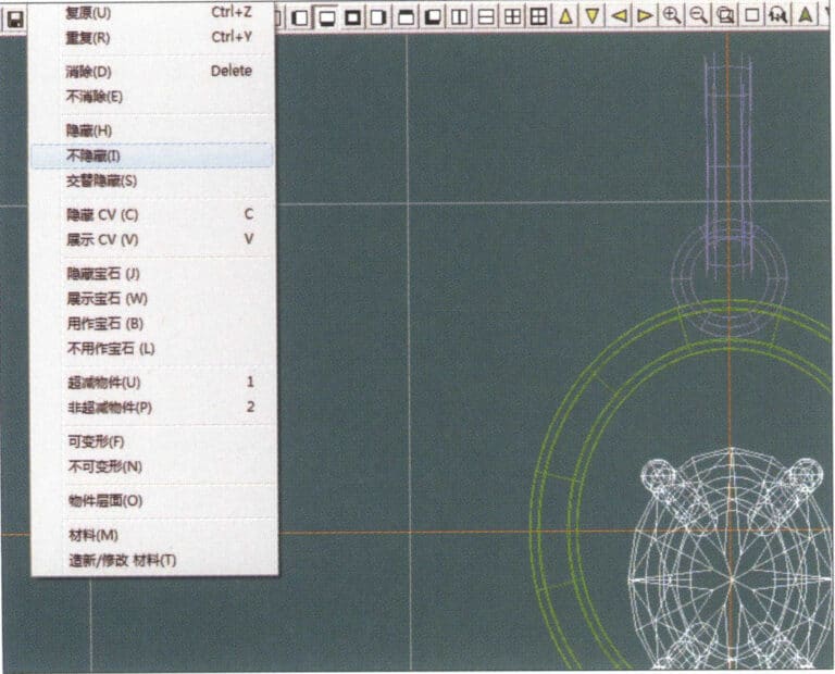
31. Select "Edit" > "Unhide" from the menu bar to display the hidden objects
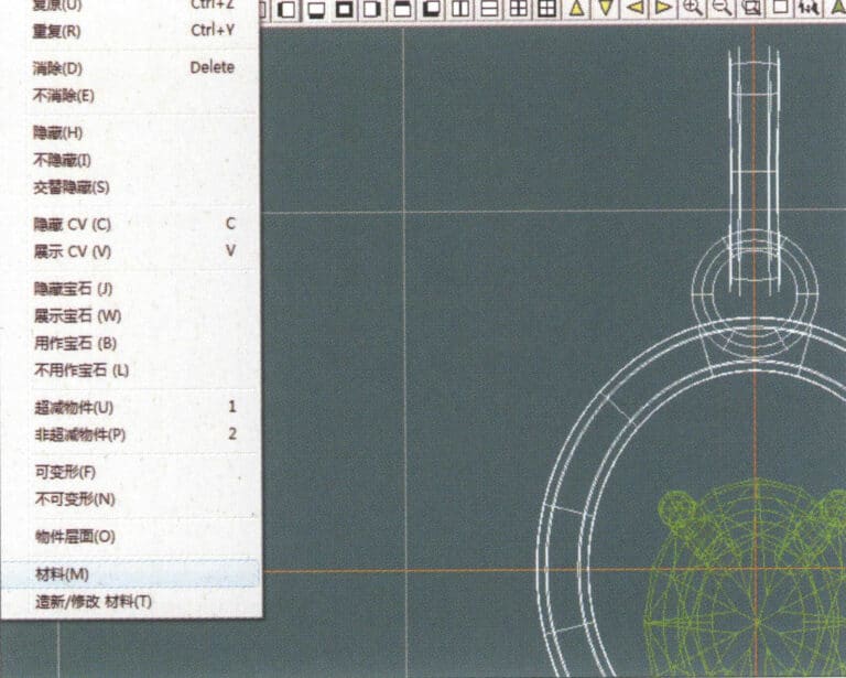
32. Select "Edit" > "Materials" from the menu bar
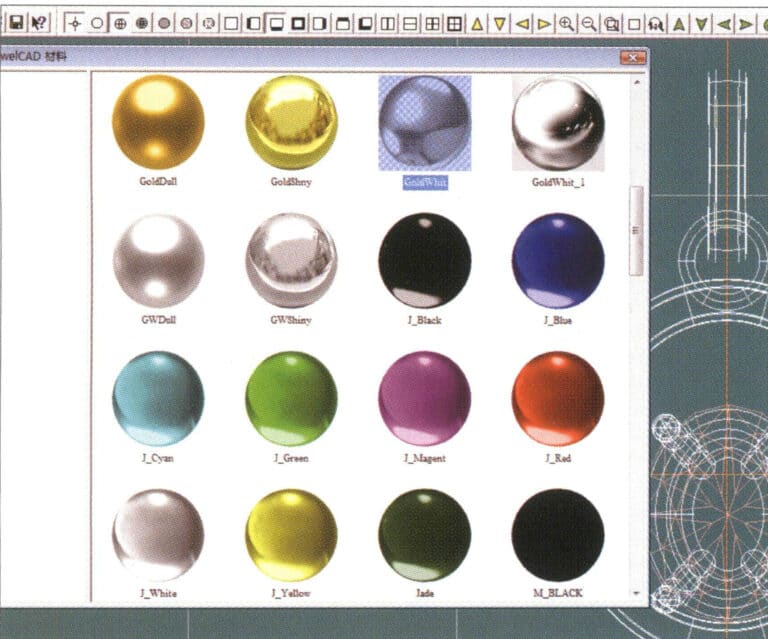
33. Przejdź do okna dialogowego "Materiały", wybierz odpowiednie materiały i potwierdź.
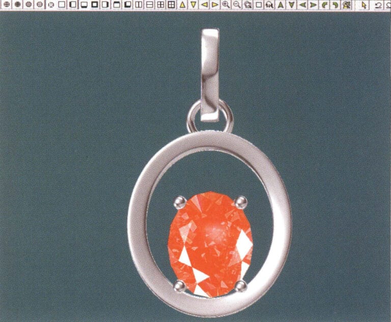
34. Select "View" > "Shadow Map" from the menu bar to inspect the shadow effects
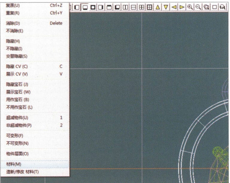
35. Select "Edit" > "Materials" from the menu bar
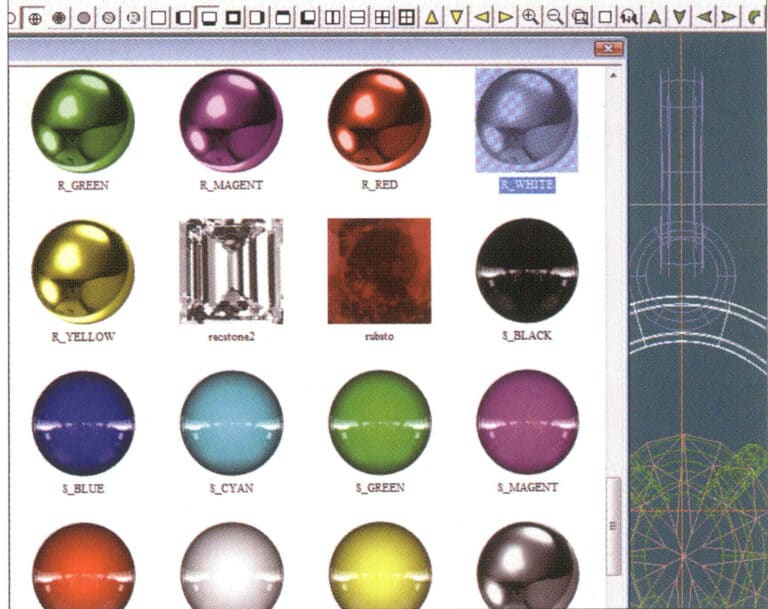
36. Przejdź do okna dialogowego "Materiały", wybierz odpowiednie materiały tekstur i potwierdź.
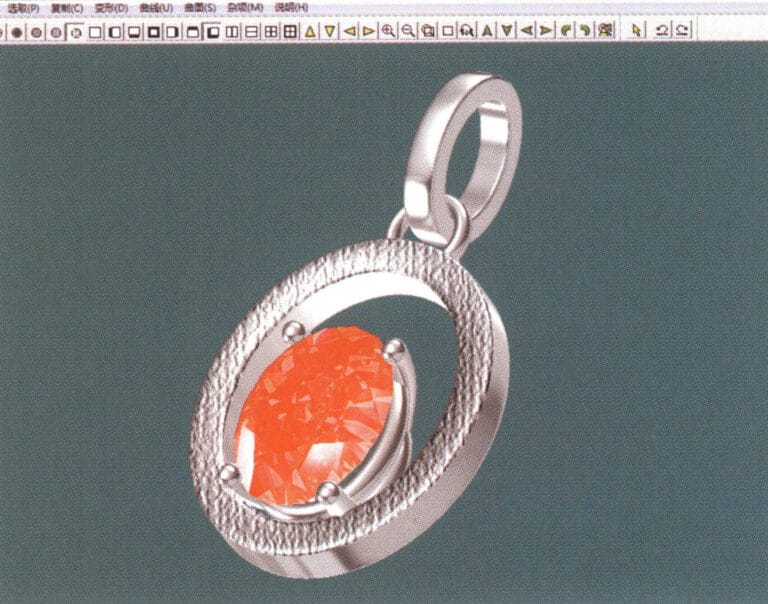
37. Select "View" > "Shadow Map" from the menu bar to inspect the shadow effects
38. Select "File" > "Save As" from the menu bar to save the file


