How to make Jewelry Master Mold ?
Insider's Guide to Jewelry Master Mold Making Techniques and Processes
Giriş:
Mold making is the “source” of the jewelry manufacturing process. All jewelry styles designed by the design department must be made into template by the molding department before they can be mass-produced. The most important aspect of jewelry molding is “faithfulness to the jewelry master mold,” meaning that the production of the jewelry master mold version must strictly adhere to the requirements of the design drawings. To achieve this, the operator must first use three-dimensional thinking to deeply experience and understand the designer’s ideas and themes while also considering the jewelry master mold version’s overall integrity, coordination, aesthetics, operability, and surface quality. The molding quality directly affects subsequent procedures’ processing difficulty and the finished product’s quality.
Currently, the main methods of jewelry molding include handmade silver molds, hand-carved wax molds, and mechanical molding. Handmade silver molds are a traditional craft, and as people continuously pursue perfection, the design patterns are constantly changing, leading to ongoing updates and improvements in the handmade silver mold process. At the same time, with the continuous development of science and technology and the practical needs of enterprises to improve production efficiency and reduce production costs, new molding processes such as hand-carved wax molds and mechanical molding have gradually formed.
Generally, when a jewelry company receives a customer order that requires molding, the technical staff first understands the customer’s requirements and the complexity of the workpiece, production cycle, and quantity based on the order and then determines the corresponding molding process.
İçindekiler
Section Ⅰ Handmade Silver Mold Process
Handmade silver molds refer to creating sharp-edged, clearly defined, and smooth-surfaced originals using silver alloy through sawing, filing, welding, and chiseling methods. From this perspective, manually making silver molds is similar to the manual jewelry production process. However, compared to general manual production, making silver molds requires higher craftsmanship. It requires that the surface, hollow parts, and back of the silver mold be flawless, that the structure of each part is reasonable, and that the dimensions of the gemstone settings are accurate. Some also require pre-processing of the setting areas, such as grooving the inner wall of the bezel for set stones, creating prongs around the holes for prong-set stones, or grooving the inner wall of the channel for channel-set stones. Therefore, making silver molds is the process with the highest craftsmanship requirements in jewelry production, and the quality of the mold’s output entirely depends on the manual skills of the mold maker.
1. Use of Tools
Wind ball, welding gun, ring iron, hand-sized stick, bow saw, saw blades (various models), pit iron, file (large, medium, small), triangular file, square file, sliding file (large, medium, small), scissors, sandpaper, internal caliper, vernier caliper, flex shaft, teeth
burs, ball burs, umbrella burs, drill burs, hair brush, welding tile, line board, tablet press, etc.
2. Process Flow
Unlike manual wax carving and computer wax carving, the manual production of silver Jewelry Master Molds usually involves breaking down a workpiece into several parts, processing each part separately, and then welding the finished components with a welding gun to form a complete silver Jewelry Master Mold. For silver Jewelry Master Molds with more complex structures, methods such as blanking are used, and the general process is as follows.
(1) First, decompose the complex master mold in the jewelry design drawing into several parts and produce each part, such as various settings, floral leaves, floral wires, floral heads, skeletons, etc., in advance for later use.
(2) Prepare a piece of copper plate (or wooden board, aluminum plate, plastic plate), and pile the clay into a hemispherical shape on the copper plate (the diameter of the hemisphere should be equivalent to the ring’s band).
(3) First, press the main stone’s setting into the clay, ensuring the depth is appropriate; it should not be too deep or too shallow. Then, press the side stone’s setting into the clay according to the drawing, arranging them neatly. Press the leaves, flower wires, and framework into the clay according to the drawing, arranging them neatly. Insert the claws of the various settings into the gaps between the various settings and other components, ensuring they are flush with the corresponding settings. Pay attention to the claws’ symmetry; their length should be slightly longer than the dimensions indicated in the drawing (if it is not a claw setting, this step can be omitted).
(4) Roll a piece of 50mm x 50mm x 0.4mm iron sheet into a cylinder, weld it (or secure it with adhesive tape), and insert it into the clay surrounding the arranged components. Slowly pour the prepared plaster slurry along the inner wall of the cylinder, filling it close to the depth of the cylinder. Leave it at room temperature for 2-3 hours, and after the plaster naturally solidifies, turn the plaster cylinder upside down, carefully remove the clay, and gently brush it in the gaps clean with a brush dipped in gasoline.
(5) Air-dry the residual gasoline and weld the exposed back of the jewelry master mold model. While still hot after welding, place the plaster cylinder into cold water to “wash off” the plaster; use a steel needle to pick out the remaining large pieces of plaster, and soak the jewelry master mold model in dilute sulfuric acid for 10 minutes, then rinse it clean and dry it with a hairdryer.
(6) Check the front of the jewelry master mold model for any weak welds, missed welds, or deformation. If any are found, they should be repaired and corrected. Once correct, trim off the excess claws (on both sides).
(7) Weld single, double, or triple sprue lines according to the volume and complexity of the silver model and file the weld seams.
(8) File, sandpaper, and polish the entire silver model until the surface is bright and clean, the patterns are symmetrical, and the lines are smooth, then proceed to the next process for rubber molding and wax injection.
Notes: Placing the model is the most critical step in the silver model production process. The placement of a bad shape directly affects the overall quality of the workpiece. Operators should fully utilize their imagination based on the order drawings, conceive the three-dimensional effect after the bad shape, and continuously adjust the bad shape with their skilled techniques to ensure that the structure of the bad shape is accurate, layered, has a strong three-dimensional sense, and is vivid and realistic.
Section II Hand-Carved Wax Model Process
1. Introduction to the wax materials used for hand carving.
1.1 Properties of Wax Materials
Wax is the basic material for hand-carved wax models. Various types of wax are used in the jewelry industry, but only a few are suitable for carving. Most wax materials are either too brittle or soft, making them difficult to carve using conventional methods. Five aspects are mainly considered to evaluate whether a wax material is suitable for carving: hardness, strength, toughness, uniformity, and melting point.
The wax material used for carving should have sufficient hardness to carve out the details of fine patterns.
Since the thickness of jewelry is generally thin, with some pieces having a thickness of less than 0.3mm, the wax material used for carving must have sufficient strength and toughness so that the thin wax does not deform or break.
The wax material should also have a uniform density, and the wall thickness of the wax must be consistent to ensure that the patterns on the wax model have the same clarity. The method to judge wall thickness is usually simple: hold the wax model up to the light to saw if the color is the same everywhere. When the wall thickness is different, the colors will vary. However, when the density of the wax material is uneven, even if the wall thickness is the same, it may present different colors, which could lead to misjudgment during operation.
For wax patterns directly used in investment casting, the wax material must also easily melt away during the roasting process, have low thermal expansion, and leave minimal residue after roasting.
The industry’s well-known brands of carving wax materials include Ferris, Matt, and Kerr.
1.2 Classification of wax materials
Due to differences in performance and processing characteristics, various categories of wax materials are used for carving, which are usually classified according to hardness, shape, and purpose.
(1) Classification by hardness.
Based on the different hardness of carving wax, it is generally divided into three categories: high hardness wax, medium hardness wax, and soft wax. For ease of distinction, green, purple, and blue represent them. For example, the characteristics of the three types of carving wax are as follows: Ferris brand carving wax.
Green wax: This wax has the highest hardness and the lowest elasticity and softness. Green wax is the most widely used carving wax, capable of carving sharp angles and intricate details in wax models. It can be processed to a thickness of less than 0.2mm, maintaining its shape well without easily deforming, and polished to a smoothness like glass. Due to its lower toughness, green wax is prone to cracking when carving large and thin curved surfaces. The melting temperature of green wax is 230°F(110℃), and when it melts, it immediately turns into liquid rather than slowly becoming liquid after a viscous stage. To create surface textures, green wax can be easily cut and filed using various wax saws, carving knives, wax files, and machine burss.
Purple wax: Purple wax has medium hardness, good elasticity, and softness and is suitable for making wax models with more complex structures. The melting temperature is 225°F(107℃). When purple wax melts, it first becomes viscous before turning into liquid, and its viscosity changes during melting, becoming softer, making it less capable of holding fine patterns.
Blue wax: Blue wax has the lowest hardness and is very soft, which makes it suitable for making general wax models with simple structures, especially for works with circular or curved surfaces. Blue wax is best carved with a knife, as it does not produce wax powder like green wax or flake off like purple wax. Blue wax melts at 220°F(104℃) but does not turn into a flowing liquid; it maintains a certain viscosity. Blue wax is very convenient for copying surface patterns of master models, but it is not suitable for making very fine patterns and is not for processing with a flex shaft.
(2) Classification by shape and use.
In terms of shape, there are block, sheet, tube, strip, and line wax materials; to facilitate production use, save processing time, and reduce wax material loss, there are also various pre-shaped wax materials or wax accessories available for selection, such as ring wax, bracelet wax, inlay wax, claw wax, and other auxiliary shaping waxes. The shapes, characteristics, and uses of various wax materials are shown in Table 2-1.
Table 2-1 Commonly used wax materials for manual carving
| Balmumu Malzeme Kategorisi | Şekil | Özellikler | Uygulama Aralığı |
|---|---|---|---|
| Sert Balmumu (Balmumu Tuğlaları, Balmumu Levhaları, vb.) |

|
Yüksek sertlik, mükemmel işleme performansı, oyma için çok uygun | Takı, süs eşyaları ve el sanatları oymacılığı için balmumu modeller |
| Yumuşak balmumu |

|
Düşük sertlik, bükülmesi ve deforme olması kolay, serbestçe şekillendirilebilir | Bitki yaprakları, sarmaşıklar ve böcek kanadı dokuları gibi çizgi tasarımlarına sahip biyomimetik aksesuarlar |
| Halka balmumu |

|
Halkalar için tasarım, işlem süresinden tasarruf sağlayan hem katı hem de içi boş tiplerle saf yuvarlak ve "U" şekilli platformları içerir. | Erkek ve kadın yüzükleri yapımı |
| Bilezik balmumu |

|
Yuvarlak, oval ve kare bilezikler yapmak için kullanılabilir, işlem süresinden tasarruf sağlar | Bilezik yapımı |
| Kakma mumu |

|
Shape and size standards, good strength, not easy to break | Standard gemstone inlay |
| Pençe mumu |

|
Has good elasticity, can be bent, not easy to break | Claw setting and linear shape |
2. Common Tools for Hand-Carved Wax
Compass, caliper, triangle ruler, bow saw, specialized wax saw blade, small lathe, chuck, triangular burs (homemade), flat chisel, scalpel, round file (large, medium, small), flat file (large, medium, small), electric soldering iron, bamboo leaf file, flex shaft, drill burs, ball burs, teeth burs, umbrella burs, large polishing burs, wave burs, hair brush, sandpaper, rings size planer, internal caliper, etc.
3. Basic Process of Hand-Carved Wax
The basic process of making a hand-carved wax mold is as follows.
Review the Material List → Carve out rough blanks → Forming fine details → hollow out caged back → Open the setting position → Modified Wax Model
3.1 Review the material list
Review the material list when the production staff receives the order, they must first understand the customer’s requirements based on the order, such as size, the size of the gemstones, and the specified wax weight. Therefore, it is essential to understand the specific meanings of the following terms.
(1) Ring size. The inner diameter of the ring, usually measured in US and Hong Kong sizes, needs to be measured with a ring sizer.
(2) Bandwidth. Refers to the width of the ring at its lowest point.
(3) Shank thickness. Refers to the thickness of the ring at its lowest point.
(4) Edge height. Refers to the vertical height of the edge of the ring’s head.
(5) Side height. Refers to the total height from the side of the setting mounts, which needs to be measured with a caliper.
(6) Thickness of the smooth part. Refers to the thickness of the area around the setting mounts without inlaid stones. Measured with an internal caliper, usually taken as 0.6-0.7mm unless the customer has special requirements.
(7) Thickness of the prong position. Refers to the thickness of the position where the stones are inlaid, which needs to be measured with an internal caliper. If the customer has not provided requirements, it can be taken as 1 ~ 1.2mm.
(8) Thickness of the stone inlaid edge. Refers to the thickness around the stone inlaid position of the setting mounts, which can be taken as 1.1-1.3mm.
For the location of the above terms, saw Figure 2-1.

(9) Size of the gemstone. Refers to the dimensions of the gemstone. Some orders come with stones attached, and the setting can be made based on the actual size; if the order does not include stones, the size range of the gemstone must be determined according to the code.
(10) Wax weight. This refers to the quality of the wax product after hand-carving it, which can control the quality of the silver mold and the workpiece.
Under normal circumstances, the ratio of wax to metal is as follows:
wax : silver = 1 : 10;
wax : pure gold = 1 : 20;
wax : 18KY = 1 : 15;
wax : 18KW = 1 : 15.5;
wax : 14KW = 1 : 14.5;
wax : 14KY = 1 : 14;
wax : 10KW = 1 : 10.5;
wax : 10KY= 1:10
(KY refers to yellow gold alloy, KW refers to white gold alloy, such as 14 KY refers to 14 K yellow gold alloy, 18 KW refers to 18 K white gold alloy).
Select a suitable wax material for the workpiece based on the above dimensions. The overall size of the wax material must be larger than the overall size of the workpiece. For regular workpieces, the overall size can be measured directly from the drawing using calipers or a compass, slightly enlarging it based on the simplicity and shape of the drawing, then marking the line on the wax material, and cutting along the marked line with the appropriate tools. Different wax materials have different cutting methods: when cutting hard wax bricks, a wood saw or metal saw can be used; for small hard wax profiles, a bow saw equipped with wax saw blades can be used; when cutting soft wax, due to its soft texture and high stickiness, it is easy to stick to the saw blade when using a saw blade, so using a knife blade for cutting is more convenient.
The precautions are as follows.
(1) When cutting hard wax, if the cutting speed is too fast, the heat will not dissipate in time, causing the wax shavings to stick together and also to the saw blade, making cutting difficult and even breaking the saw blade. Therefore, pay attention to the force and speed when cutting, and do not solely pursue speed.
(2) It is very easy to deform When cutting soft wax due to its low hardness. Therefore, placing the soft wax on a flat support when cutting is best. It is better to finish cutting the wax material before making the patterns for soft wax with patterns. Additionally, the tools used should be sharp, and the angle between the blade and the surface of the wax piece should be minimized to prevent tearing or wrinkling of the wax material during the cutting process.
(3) Since there will be a certain amount of consumption of the wax material during actual processing, and to account for casting shrinkage, it is necessary to leave enough allowance when cutting, generally around 15% of the finished product. Additionally, note that when rings, pendants, and earrings are paired, the sizes of the setting mounts differ; generally, the ring and pendant are 0.3mm larger than the earrings.
3.2 Carve out rough blanks
Use a compass and triangle to draw the main lines on the material, including the inner and outer contours. Use a thick saw blade to sew off the excess parts along the drawn lines, install the turning burs on the flex shaft for preliminary processing, and create a rough outline. Then switch to a tooth burs to smooth out the deep marks and burrs left by the blade Finally, use a file to remove the marks the tooth burs leaves, making the surface smooth.
If, during the processing, the wax acciteethly shows signs of missing edges or corners, use an electric soldering iron dipped in wax to fill in the gaps. When adding wax, please pay attention to the temperature of the soldering iron, as it should not stay in the same position for too long.
3.3 Forming fine details
Based on the rough blank, further refine the rough blank to make the entire wax model more delicate, more beautiful, and more in line with the design requirements, forming fine details.
First, a compass takes the dimensions of each part of the wax model and draws some auxiliary lines. Then, according to the auxiliary lines, use the turning burs to remove the excess wax and the tooth burs to smooth out the rough marks left by the previous process. Depending on the wax model, you can also directly use the flat parts of different-sized files to smooth the surface or outer edge of the wax model. Use various spatulas to flatten any corners or protruding parts on the wax model, and refine with a scalpel. Use various smooth files to smooth the overall wax model. The bamboo leaf file has the finest texture, so it is used as the final step, resulting in a better effect for the wax model after this process.
When making, be aware that the wax model should be larger than its drawing by about 3%, reserved for the loss during the mold and shrinkage during casting.
3.4 Hollow out caged back
The purpose of hollow out caged back is to reduce the weight of the workpiece. Install the ball burs and wheel burs on the flex shaft, and use the ball burs to remove excess wax material from the bottom of the setting mounts or the inner circle of the ring shank. Generally, the thickness of the base for the prong setting is 1.1mm; for the polished metal and bezel setting, it is 0.7mm; for the full bezel setting and channel setting, it is 1.6mm. Then, use a teeth burs, drill burs, knife, etc., to trim the frame at the bottom of the wax model. During the cut caged back process, frequently use internal calipers to measure the dimensions at the polished metal position (referring to the smooth surface areas of the metal jewelry blank excluding the setting edge, floral decorations, ring shank, etc.), prong setting position, channel setting position, etc., to prevent deviations.
3.5 Open the setting position
According to the size and dimensions of the gemstone, open the stone setting position according to the setting method. For channel setting and full bezel setting, select the appropriate drill burs based on the shape and size of the gemstone, drill holes at the designated stone positions, and then use a teeth burs, small file, knife, etc., for trimming. A teeth burs can also be used to open the stone position directly.
3.6 Modified Wax Model
The modified wax model is an adjustment of some details that arise in the wax carving process to make the produced wax model more in line with the order’s requirements (workpiece). When modifying the wax model, the following points should be noted.
(1) Quality of the wax sample. The wax weight is adjusted according to the requirements of the order for the quality of the jewelry product, since the quality of the metal used can be determined by calculating the ratio of the wax to the mass of the various metals. The method of controlling the quality of the wax samples is mainly to increase or decrease the wax weight by modifying the wax base.
(2) Dimensions of each part. All dimensions must be consistent with the data in the order’s drawings; if there are no dimensions, common dimensions can be used to determine them.
(3) The relationship between quality and size needs to be coordinated.
4. The hand-carving wax process of typical jewelry
4.1 The wax carving process of solid gold rings
Solid gold rings mainly use shallow relief craftsmanship, and the main process flow is as follows.
(1) According to the specifications and dimensions of the pattern, measure the dimensions with a caliper, draw lines, and use a hacksaw to cut the required wax block (Figure 2-2).
(2) Place the sawn wax block on a file to smooth it out, creating three right-angled faces, where the front view and top view are at right angles, the front view and side view (left or right) are at right angles, and the top view and side view are at right angles (Figure 2-3).

Figure 2-2 Sawing Wax

Figure 2-3 Wax Block
(3) After the three right-angled faces are polished, use a caliper to draw the center vertical line (including the top and back) and the horizontal line of the ring base height along the right angle edge (Figure 2-4).
(4) Use a compass with the horizontal line of the ring base and the center vertical focal point as the starting point, and with the radius of a hand inch at the point on the vertical line as the center, draw the arc line of the hand inch (including the back, Figure 2-5).

Figure 2-4 draw baseline.

Figure 2-5 Drawing Processing Line
(5) Drill a small hole on the inner side of the arc, pass the saw blade through, and use a coping saw to cut out a hand-sized hole along the inner line of the arc (Figure 2-6).
(6) Use a wax machine burs to trim the inner circular edge, then use a Wax Ring Stick Reamer Tube Sizer to scrape out the hand-sized scale reading, making both sides the same size (Figure 2-7).

Figure 2-6 Saw hand hole

Figure 2-7 Rotating scraping hand hole
(7) Use a flex shaft burs to shape the ring’s outer form, use a file to make the left and right edges symmetrical, and smooth the bottom edge (Figure 2-8).
(8) Use calipers to draw the centerline on the side, set the width of the ring base and bottom edge, and sew the two side edges with a sewing machine burs. If the men’s ring has double-slanted straight edges, place it on a file to grind it into a diagonal, symmetrical shape. Be careful to maintain the overall shape of the ring and use a small wax file to correct it, ensuring all four sides are neat and symmetrical.
(9) Use a chuck needle to draw the pattern (letters, shapes, or designs) on the ring base (ring face), and use a diagonal knife or medium-sized knife to carve the inner border line, engrave the letters, and outline the outer border line (Figure 2-9). Use a side knife to hollow out the gaps between the frame and letter edges (shape edges), then use a flat-bottom knife to finish the bottom.

Figure 2-8 Shape repair

Figure 2-9 Carved Pattern
(10) Observe the ring face from a distance, use a knife to correct the characters and shapes, and refine them carefully, making the wax piece’s layers clear, the image lively and vivid, with smooth curves and thin, rounded lines.
(11) After confirming the overall accuracy of the ring, use a burs to hollow out the wax from the inner bottom to the ring base (Figure 2-10). Leave a 1mm wall edge, with the remaining thickness 0.5 ~ 0.8mm, ensuring the wall thickness is uniform, avoiding being too thin and causing perforation or too thick and increasing weight.
(12) Use a carving knife to scrape off surface scratches, then use 400#-600 #sandpaper for coarse grinding, and then 800# ~ 1200# sandpaper for fine grinding (Figure 2-11).
(13) Wipe the waxed parts with caustic soda or White Gas.

Figure 2-10 Hollowing Out

Figure 2-11 Sandpaper Polishing
4.2 K Gold Pendant Wax Carving Process
Pendants often use a semi-circular carving technique, which is a combination of round carving and relief carving. The main process flow is as follows.
(1) Cut a piece of wax suitable in size and thickness compared to the design (slightly larger than the dimensions reserved in the drawing) and smooth it out to copy the front of the design.
(2) Copy the pattern onto the wax surface.
(3) Use a bow saw to follow the contour line and saw the shape.
(4) Carve the outline with a knife or use a sewing machine burs to stitch the outline, and use a file to refine the shape.
(5) A flex shaft burs or flat knife is used to scrape out the height levels according to the thickness requirements.
(6) Use a knife to carve out the rough shape of the main and secondary patterns (Figure 2-12).
(7) Observe the overall shape of the wax model, make adjustments to the local areas, and then refine it into a fine blank (Figure 2-13).

Figure 2-12 Rough carving shape

Figure 2-13 Trimming the rough blank
(8) Narrow the bottom edge line of the body (Figure 2-14).
(9) Hollow out the bottom, leaving a thickness of 1mm to ensure uniform thickness throughout.
(10) Use a scalpel to create a layer (pattern) at the “side edge” position and create a flat window (Figure 2-15) where there is no pattern.
(11) Use a carving knife to scrape off surface scratches, then use 400#-600# sandpaper for coarse sanding, and finally, use 800#-1200 #sandpaper for fine sanding.
(12) Wipe the waxed parts with caustic soda or White Gas.

Figure 2-14 repairs the "grabbing edge

Figure 2-15 opens the layer
4.3 Wax carving process for necklaces
The necklace mainly uses hollow carving techniques, belonging to single-sided shallow carving, using emptiness to highlight the clarity of the pattern (design) outline. The main process is as follows.
(1) Use a wax sheet of thickness 15 ~ 20mm to saw out the main shape.
(2) Divide the left and right extension connecting pieces into sections and saw them in order of size.
(3) The latter half of the chain can choose the smallest section and be copied using casting methods.
(4) Handle each piece individually After dividing the chain into the required number of pieces.
(5) Drill a small hole in the space of the pattern (design) and use a fine saw to cut along the decorative edge.
(6) Carve layers from the highest point of the main body to the lowest in an arc shape.
(7) The main body is primarily engraved with circular lines, with the lines suspended at the edges, creating a three dimensional effect.
(8) The necklace is continuous, with the main height gradually smooth.
(9) Use a carving knife to scrape off surface scratches, then use 400#-600# sandpaper for coarse sanding, followed by 800#-1200# sandpaper for fine sanding.
(10) Wipe the waxed parts with caustic soda or White Gas.
Hand-carved Wax Model Video
Section III Mechanical Jewelry Master Mold-Making Process
In recent years, the jewelry processing industry has increasingly emphasized introducing high-tech technologies. For example, CNC processing and rapid prototyping have enabled jewelry processing to achieve mechanization, no longer relying solely on manual operations. Moreover, the jewelry master mold versions of the processed jewelry have advantages such as high symmetry, precise dimensions, lower costs, and time savings.
The mechanical Jewelry Master Mold-making process can be divided into two types based on the method of implementation: stacking type and decremental type, which correspond to rapid prototyping technology and machine carving of the jewelry master mold version of the technology.
1. Principles of Rapid Prototyping Technology
Rapid Prototyping (RP) technology is a high-tech innovation developed in the 1990s. Since the first commercial molding machine was introduced in 1988, RP technology has been rapidly promoted and applied in the new product development activities of manufacturing enterprises in developed countries, significantly shortening the R&D cycle of new products, ensuring the time-to-market for new products and increasing the success rate of new product development, thereby effectively enhancing the competitiveness of products in the market and the ability of enterprises to respond quickly to market changes. This revolutionary new technology has also received great attention and focus from jewelry processing companies and has quickly been applied and promoted in the industry.
1.1 Hızlı Prototipleme Teknolojisinin Prensipleri
Rapid Prototyping technology is a new manufacturing technology developed based on computer-aided design, computer-aided manufacturing, computer numerical control, laser technology, and new materials. It is based on the principles of discretization and stacking, where the CAD model of the part is discretized in a certain way into processable discrete surfaces, lines, and points, and then physical or chemical means are used to stack these discrete surfaces, line segments, and points to form the overall shape of the part. The specific method involves slicing the three-dimensional CAD model of the part into layers after format conversion, obtaining the two-dimensional contour shapes of each layer’s cross-section. According to these contour shapes, a laser beam selectively solidifies layers of liquid photosensitive resin, cuts layers of paper or metal sheets, or sinters layers of powder materials, as well as selectively sprays layers of adhesive or thermoplastic materials using a jet source, forming the planar contour shapes of each cross-section, and gradually stacking them into a three-dimensional part. Rapid Prototyping technology differs from traditional “subtractive” processing methods, which remove excess material from a larger workpiece to achieve the desired part shape. Instead, it adopts a new “additive” processing method, where a layer of “thin sheet rough” is first made using points and lines, and then multiple layers of thin sheet rough are gradually stacked to form complex-shaped parts. The basic principle of Rapid Prototyping technology is to decompose complex three-dimensional processing into the stacking of simple two-dimensional processing. Hence, it is also called “layered manufacturing.”
1.2 Advantages of Rapid Prototyping Technology
In the traditional product sample development process, designers first need to form a three-dimensional image of the user’s requirements in their minds and then convert it into two-dimensional engineering drawings, which must later be converted into three-dimensional samples or models by the processors. When modifications to the product are needed, this three-dimensional to two-dimensional conversion process must be repeated multiple times. Therefore, the traditional product sample design and development process adopts a step-by-step approach, often taking a long time and extending the product development cycle.
Rapid prototyping technology integrates the concept of concurrent engineering, solving the problem of quickly and intuitively analyzing and verifying products in engineering design. This allows for the direct generation of three-dimensional solid models without the need for any intermediate engineering drawings or steps. Thus, it has the following obvious advantages.
(1) Significantly shortens the development cycle of new products and reduces the time to market.
(2) Lowers the research and development costs of new products.
(3) Increases the first-time success rate of new product launches.
(4) Supports the implementation of synchronous (concurrent) engineering.
(5) Support technological innovation and improve product appearance design.
2. Main methods of rapid prototyping technology
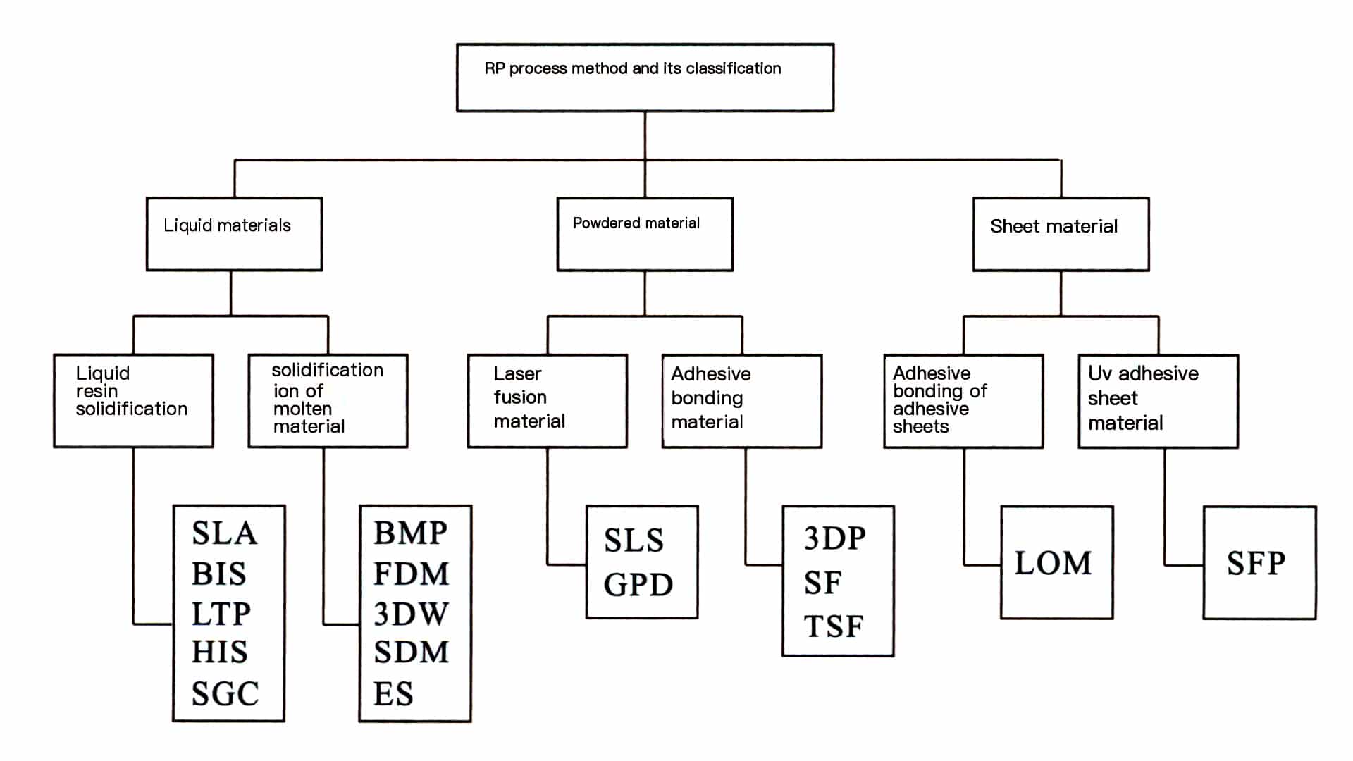
Since the first commercial SLA rapid prototyping machine was launched by 3D Systems in the United States in 1988, there have been more than a dozen different forming systems (Figure 2-16). Typical methods include SLA, SLS, LOM, and FDM.
2.1 Laser curing forming (SLA)
This molding method uses photosensitive resin as the raw material. Under computer control, a UV laser scans the surface of the liquid photosensitive resin point by point according to the cross-sectional data of each layer of the part, causing the resin to become a thin layer in the scanned area to undergo a photopolymerization reaction and solidify, forming a thin layer of the part; after one layer is cured, the workbench descends, and a new layer of liquid resin is applied on the previously cured resin surface for the next layer of scanning and curing. The newly cured layer firmly adheres to the previous layer, which is repeated until the entire part prototype is completed. The principle of the SLA method is shown in Figure 2¬17.

The characteristics of the SLA method are high precision, good surface quality, and a material utilization rate of nearly 100%, capable of producing parts with particularly complex shapes (such as hollow parts) and fine details (such as jewelry, crafts, etc.). The drawbacks are that the equipment is relatively expensive, and the lifespan of the laser tube is limited; the types of materials available are limited, and they must be photosensitive resin, which also pollutes the environment; support structures must be designed to ensure that each structural part of the prototype can be reliably positioned during the molding process.
2.2 Selective laser sintering (SLS)
This technology is very similar to SLA, using a laser beam to scan each layer of material, but the laser in SLS is a CO2 laser, and the molding with the material being powdered. During production, the powder is preheated to just below. The laser beam controls the melting point temperature to heat the powder, bringing it to the sintering temperature, thus solidifying it and bonding it with the previous layer. Currently, the materials used for sintering mainly include standard casting wax, standard engineering thermoplastics, etc. The principle of the SLS method is shown in Figure 2-18.

The advantage of the SLS method is that it does not require support, as the powder is compacted. The disadvantages are that the machines are relatively expensive, the surface of the produced parts is rough, post-processing is more troublesome, and the density of the formed parts could be better. The total forming time is similar to that of SLA.
2.3 Laser Laminated Object Manufacturing (LOM)
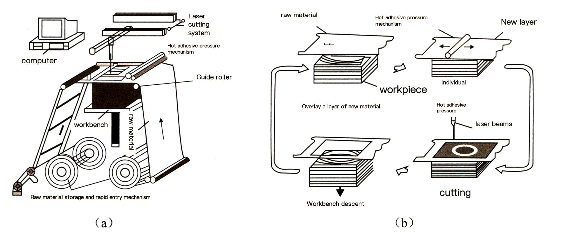
The LOM forming method cuts thin materials (such as paper and metal foil) based on the layered geometric information of the parts, sequentially bonding the obtained layers into a three-dimensional entity. A laser with a certain power is generally used for cutting; first, a layer of thin material is laid down, then the laser cuts out the profile of this layer under computer control, and the non-part portions are cut into fragments of a certain shape for removal. After completing this layer, another layer of thin material is laid down, and a heated roller is used to press and cure the adhesive, bonding the newly laid layer to the already-formed shape before cutting. This technology significantly increases the forming speed of the model due to the short laser cutting time required for each layer, making it suitable for manufacturing large-sized models, mainly used for the rapid manufacturing of new product prototypes, models, or wooden molds for casting. The principle of the LOM method is shown in Figure 2-19.
The advantages of the LOM method are fast forming speed, no need for support structures, and ease of use. The disadvantages are that the prototype is prone to moisture absorption and must be painted or undergo other post-processing immediately; it cannot build complex shapes and structures for fine prototypes.
2.4 Fused Deposition Modeling (FDM)
The melting accumulation forming method uses a melting stacking approach to fill the semi-molten model material according to a certain movement pattern. The key to FDM technology lies in the melting stacking of the forming material. The nozzle of the FDM equipment moves under computer control to stack parts as required, and the forming material is extruded from the nozzle in a semi-molten state. By accurately controlling the melting temperature of the forming material and the working environment temperature, the semi-molten forming material extruded from the nozzle begins solidifying the moment it leaves the nozzle. The nozzle fills thin layers of cross-sections with a certain thickness and then stacks the three-dimensional entity of the forming parts in the height direction. The forming principle is shown in Figure 2-20.

Models made using FDM technology are very close to the actual materials in terms of performance and appearance, thus having unique advantages in manufacturing conceptual models and verifying product functions with an increasingly broad range of applications.
Copywrite @ Sobling.Jewelry - Özel takı üreticisi, OEM ve ODM takı fabrikası
3. Main rapid prototyping technologies used in the jewelry industry
In the jewelry manufacturing industry, rapid prototyping technologies mainly include SLA and FDM methods. Among them, a typical representative of the SLA method is the MEIKO computer-aided design machine developed by the Japanese company MEIKO, and the Envision TEC Prefactory rapid prototyping machine launched by the German company Envision TEC is also based on a similar principle. A typical representative of the FDM method is the series of wax printers produced by the American company Solidscape.
3.1 MEIKO Computer-Aided Design Machine
The jewelry-specific computer-aided design machine developed by MEIKO has a certain history and high usage rate in the jewelry processing industry. This model uses photosensitive resin as the model material, utilizing ultraviolet lasers to cure the resin, forming prototypes through layer-by-layer scanning and stacking. The company has launched the latest MEIKO LCV-700 model (Figure 2-21).

The MEIKO machine has the following advantages.
(1) Accepts data from 3D CAD designs (JSD, DXF, STL formats), interprets NC data produced by CAM software, uses low-power lasers for scanning, and stacks layers after resin curing to quickly and accurately create 3D physical objects.
(2) Uses high-sensitivity, specialized resin for fine modeling, with low viscosity, no pollution, and minimal shrinkage.
(3) Resin prototypes can be directly used to create rubber molds.
(4) Fully computer-controlled, capable of producing multiple different models simultaneously. Shapes that are difficult to complete manually can be accomplished, greatly reducing the defects that may arise during manual prototyping and ensuring that the model matches the design data consistently.
(5) Precision can reach 0.01mm, with high stability and easy typesetting and operation.
(6) The compact equipment can be placed in a typical office.
The operating procedures for the MEIKO first edition machine are as follows.
(1) Preparatory work before starting.
- Convert the 3D CAD design data into NC data and securely connect the CNC cable of the prototyping machine to the serial port of the computer.
- Check if the resin level in the resin container is at the minimum scale line; if not, add resin to the middle reference line, clean up any dripping resin, and close the processing chamber door tightly.
(2) Start.
- Set the main switch of the printer to the ON position, connect the power, and the LCD of the printer will show a prompt.
- Open the laser power door at the bottom right and connect the laser power; at this time, the laser needs to prepare for a while, approximately 15 ~ 20 min. When the LCD prompts “the laser active,” preparation is complete.
- Press the origin reset button on the printer’s control panel; the resin platform and laser head will return to the origin. When the LCD prompts “Start forming,” the printer enters working status.
(3) Processing operation.
- Transfer the CNC data to the printer via the computer, first creating the resin support.
- The UV laser scans the surface of the liquid photosensitive resin point by point according to the cross-sectional data of each
- layer of the workpiece, curing the thin resin layer in the scanned area.
- After one layer is cured, the workbench descends, and a new layer of liquid resin is applied to the previously cured resin surface for the next layer of scanning and curing.
- Repeat this process until the entire prototype of the workpiece is completed. Note that the processing chamber door must not be opened during the operation; otherwise, the processing will be interrupted and cannot continue.
- When the processing is complete, the printer’s buzzer will sound three beeps to indicate the end of processing; press the origin reset button.
- Once the laser head and platform have returned to the origin, open the processing chamber door to pull out the platform, place it on a prepared soft cloth pad, and close it to prevent light from entering.
- Gently scrape off the cured resin mold with a flat spatula, carefully not to scratch the platform. This operation should not be performed while the platform is installed to avoid damaging the printer’s precision.
- Clean the cured resin on the platform thoroughly; if too much is adhered to, use alcohol to clean it and secure the platform on the platform rack.
- Use tweezers to pick up the scraped resin mold and place it in a beaker filled with alcohol for rinsing, being careful not to exceed the rinsing time.
- Place the rinsed resin mold under a UV lamp for 1-2h secondary curing. For larger products, flip them over to ensure more even exposure. After the resin model is fully cured, check the model quality; any defects should be repaired before pressing the rubber mold.
(4) Shutdown.
- Confirm that the laser head and platform have returned to the origin; otherwise, press the origin re-scan button.
- Confirm that the processing chamber door is closed and locked.
- Turn off the laser and main switch power supply.
- Set the main switch off the Jewelry Master Mold-making machine to the OFF position, cut off the power supply, and turn off the uninterruptible power supply switch.
3.2 Germany Envision TEC Perfactory rapid prototyping machine
In 2004, the German company Envision TEC launched the Envision TEC Perfactory rapid prototyping machine (Figure 2¬22). This model uses DLP digital image projection technology, and the projection system employs the most advanced DMD chip, which contains 1.3 million regularly arranged interleaved micro-mirrors, each the size of a 1/5 hair strand. Each micro¬mirror will adjust according to the image and is controlled by individual micromotors to adjust the angle, emitting light to project the image. The system converts the cross-sectional profile information of the three-dimensional model into a bitmap image, which is projected onto the resin through a DMD chip, causing it to cure and form. During the forming process, different resin materials can be selected; red resin has a higher hardness and is suitable for molds; yellow resin has a relatively low melting point, suitable for direct casting (molding).

The Envision TEC Perfactory rapid prototyping machine has many outstanding advantages.
(1) Fast forming speed and high efficiency. It utilizes projection principles for forming, so the forming speed does not change regardless of the size of the workpiece. Compared to other rapid prototyping machines, this model requires the shortest working time, which is especially evident during mass production. For example, producing ten prototypes of women’s rings can be done simultaneously in 3/i.
(2) High model accuracy and good surface finish. The X/Y resolution reaches 35 um, with a minimum layer thickness of 25 um.
(3) Low cost of use: it does not use lasers for curing and forming but instead uses very cheap bulbs for illumination. The entire system also has no injection parts, thus avoiding the common issues of clogging or damage to the laser tube found in other forming systems, reducing maintenance costs and saving time.
(4) The model can replicate wax molds using a pressure mold or directly cast into shape.
(5) The machine is compact, has low environmental requirements, is suitable for general office environments, is non-toxic, and has low power consumption.
3.3 American Solidscape series wax printers
Among the rapid prototyping machines used in the jewelry processing industry, the series of wax printers produced by Solidscape in the United States, based on the FDM method, has significant practicality and commercial value. The early model was the Model Maker II, and with various improvements made specifically for the jewelry industry, the latest models introduced are the T66 Benchtop II and T612 Benchtop II (Figure 2-23). The improved T series excels in speed and quality have significantly improved compared to the past.

(1) The basic structure of the T66 wax printer.
The T66 rapid prototyping machine can be divided into two main parts: software and hardware. The software part mainly comprises Quick Slice, which the operator specifies regarding the layered data, slicing the three-dimensional computer model as needed. After processing, it generates the device’s driving files based on the given material and path parameters, which drive the hardware system through the interface. The device’s hardware mainly consists of three major systems: (1) The three-coordinate numerical control system comprises a working platform system that moves along the z coordinate and a nozzle system in the x-y directions. (2) The material supply system for the forming materials is composed of two data-driven systems that control the model material and support material, respectively, driving the materials according to the data parameters determined during software processing, forming filling layers at a certain flow rate and speed. (3) The temperature control system, which controls the melting temperature of the materials and the working environment temperature, usually keeps the temperature of the forming materials about i℃ higher than the solidification temperature and the working environment temperature at 16-27℃.
(2) Characteristics of the T66 wax injection machine’s forming process.
The prototypes made with T66 use jewelry wax as the material, which can be directly used for lost-wax casting. The prototypes produced generally have good surface smoothness and high dimensional accuracy. No support is needed, as the Model works software that comes with the T66 automatically calculates the position of the supports, creating them during the forming process. The supports wrap around the model, and once the forming is complete, the molten wax dissolves the supports, resulting in a jewelry wax model. Therefore, in terms of material performance and appearance, it is very close to the actual product. It has unique advantages in manufacturing conceptual models and verifying product functions, broadening its application range. However, the machine also has areas that need improvement, such as production speed being relatively slower compared to SLA methods, the nozzle being prone to clogging and damage, and high maintenance costs.
(3) The process of the T66 wax spraying machine handling the jewelry master mold jewelry.
- Use jewelry CAD design software to create a three-dimensional graphic of the jewelry.
- Convert the graphic file into an STL file format that can be processed by rapid prototyping software.
- The rapid prototyping data processing software layers the model (slicing out the cross¬sectional shapes on each contour line). (4) Process each cross-section to identify the areas and shapes that need support and form the supports.
- Fill each cross-section with appropriate parameters to create a thin layer of a certain thickness under the nozzle’s movement.
- Transfer the processed device driving data to the wax spraying machine to begin rapid prototyping processing. The wax spraying machine uses jewelry-specific wax as the model material, typically using two types of wax: one is red wax, which has a lower melting point and is used for outer supports; the other is green wax, which has a higher melting point and is used to form the model. Each time the nozzle scans, it deposits a layer of wax, and then the adjacent scraper moves over to level the top surface of the model, ensuring each layer’s height is consistent. The smaller the thickness of each layer, the higher the surface precision, but it takes longer, reducing efficiency; the larger the thickness of each layer, the faster the speed, but steps may appear on the surface, affecting precision and surface smoothness.
- Once the entire model is processed, remove the wax piece and place it in a heating chamber to bake, with the temperature above the melting point of red wax but below that of green wax, causing the red wax to melt while the green wax remains unchanged. The model with melted red wax is then cleaned in a special cleaning solution to remove any residual red wax, and after blowing dry, a complete green wax piece is obtained, which can be directly used for investment casting.
4. CNC Carving Original Process
The CNC carving process involves using machine equipment to carve materials and removing unnecessary parts to obtain the jewelry master mold jewelry. This process mainly uses small CNC engraving machines, which can process resin, plastic, and wax materials and directly process metal materials. It is skilled in processing irregular structures and can create complex three-dimensional profiles and textures. The CNC engraving machines used for jewelry forming are small, with typical models including Beijing Jingdiao Carver300, France’s Gabar IS200, and Japan’s Roland Jwx-10 jewelry engraving machine. Engraving machines typically recognize various CAD software data formats, such as common Solidworks, Teehgem, ArtCam, JCAD3, or Jewel CAD. However, due to the special nature of the tools used in jewelry cutting and forming engraving, there are quite small angle and feed rate controls, and using Type3 software can achieve better processing accuracy.
4.1 CNC Carving Original Process
According to the different structural designs of various ornaments, mechanical engraving can be divided into two types: flat engraving and rotary engraving.
(1) Flat engraving.
Flat engraving refers to engraving on one side of the wax material, generally used to carve relief-style ornaments, such as pendants, brooches, and other flat accessories in jewelry. Taking the Roland Jwx-10 jewelry engraving machine as an example, the steps are as follows:
- Create a jewelry model in 3D modeling software and save it in DXF or STL file format.
- Fix the wax material on the engraving machine’s engraving table, turn on the engraving machine, and set the tool origin.
- Open the engraving software, select “File-Mechanical Selection,” turn off the rotary axis in the options, and import the model file into the engraving software.
- Surface processing, mainly to smooth the surface of the wax material; if the surface has already been smoothed, this process can be skipped.
- Rough processing refers to using a large tool to carve out the wax material’s blank. Generally, jewelry is relatively small, and a 0.5mm pointed tool can be used for rough processing.
- Finishing is the step to complete the ornament, generally using a tool of 0.2mm.
- Remove the engraved wax piece from the engraving table and refine it into a finished product.
The main processes of flat engraving are shown in Figure 2-24.

(a) Modeling

(b) Calculate the cutting path

(c) Engraving

(d) Rough blank
Figure 2-24 Main process of flat carving
It should be noted that due to the mechanical iron-cutting processing method used by the wax carving machine, some areas cannot be carved successfully in one go and need manual adjustment. During the carving process, to ensure that the wax mold has sufficient mechanical strength, extra wax needs to be left on the wax mold as support. After the carving is completed, the supporting wax must be manually removed, and the supporting areas must be appropriately adjusted. When carving a ring, the bottom area cannot be carved, and after the wax mold is completed, manual work is required to hollow out the bottom.
(2) Rotational carving.
Rotational carving generally refers to the carving of rings, achieving circular carving under the drive of a rotating axis. The steps are as follows:
- Create a model of the jewelry in 3D modeling software and save it in DXF or STL file format.
- Fix the wax material on the rotating axis, turn on the carving machine, and use the automatic tool setting function to set the origin position.
- Open the carving software, select “File-Mechanical Selection,” open the rotating axis in the options, and import the model file into the carving software.
- Surface processing, rough processing, fine processing, and adjustment are consistent with flat carving.
The main process of rotary engraving is shown in Figure 2-25.

(a) Output file

(b) Engraving

(c) Finishing

(d) Trimming
Figure 2-25 Main process of rotary engraving
4.2 Advantages and disadvantages of machine-carved originals
(1) Advantages.
Jewelry original carving machines are automated mechanical devices, and machine-carved originals have significant advantages over hand carving in terms of work efficiency, precision, and model modification. This is mainly reflected in the following aspects:
- High processing efficiency. Under the same working hours and with equally skilled operation, the number of products processed by the engraving machine is unattainable by manual labor. At the same time, the engraving machine can operate unattended, saving human resources and reducing costs.
- Good precision. Generally speaking, jewelry carving is very fine and has regular shapes. Manual carving has a larger error margin and lower precision, whereas mechanical carving can achieve precision up to 0.1mm, which is beyond human capability. Especially in carving geometric shapes and text, the engraving machine’s advantages are very obvious. In jewelry processing, engraving machines can lead to less waste and more precise quality after forming.
- Convenient model modification.
Mechanical carving allows for model preview on a computer; if there are deviations, they can be modified promptly. For size adjustments, only parameter modifications on the computer are needed. In contrast, modifying manual carvings is much more troublesome and lacks sufficient precision.
(2) Disadvantages.
The disadvantages of mechanical original carving are mainly reflected in the following aspects:
- The wax carving process is a shaping technique that can perform both additive and subtractive sculpture. However, the mechanical wax carving Jewelry Master Mold can only be used for carving. It cannot accumulate in three-dimensional space, meaning that the carving machine can only perform subtractive sculpture on materials and cannot perform additive sculpture. This weakens the expressive power of mechanical wax carving and also consumes more materials.
- The shape of the mechanical original is generally quite rigid and lacks flexibility. Handcrafted originals do not produce very standard squares or circles, but the work has a sense of simplicity. Mechanical carving makes all planes and curved surfaces close to digital standards, resulting in a stiff feel.
- Carving machines are only suitable for regular and simple jewelry shapes.
Due to the combined software and hardware limitations, it is difficult for carving machines to independently complete jewelry with large three-dimensional spatial transformations and rich textures. Generally, the carving machine first carves out the rough shape, then the details are completed manually.
Mechanical Carving Block Video
Section IV Post-Processing of the jewelry master mold
After the jewelry master mold is completed, corresponding post-processing must be carried out based on the material of the jewelry master mold, the method of copying the mold, the product structure, etc., before it can be used for production.
1. Post-Processing of Wax (Resin Molds)
For wax and resin Molds, if high-temperature vulcanized rubber is used for molding, it must first be cast into a silver Jewelry Master Mold; if room-temperature vulcanized rubber is used, it can be used directly for mold replication.
Since the wax (resin) mold has some structures that cannot be directly made, they must be added after casting the silver mold.
1.1 Recasting the silver mold
After the wax (resin) mold is qualified, it should be sent to the mold department to be cast into a silver mold (silver casting). The reason for choosing silver as the material for the mold is mainly because silver is relatively inexpensive, and its performance is quite stable. At the same time, gold is too expensive, and copper will oxidize and turn black during the molding process, affecting the quality of the rubber mold.
1.2 Polish and sanding the jewelry master mold
Adjust the surface of the silver mold cast from the carved wax and complete some processes that cannot be finished by hand-carved wax molding, mainly including the following steps.
(1) Cut casting sprue.
Observe and determine the position of the sprue, use cutting pliers to cut the sprue along the workpiece, and use a file to smooth the area where the sprue was cut.
(2) Shaping.
Shaping aims to embellish the silver Jewelry Master Mold after cutting the sprue, making its appearance more even and smooth. Pay attention to the following issues:
- Observe whether the workpiece has any deformation; if there is deformation, use burs-nose or flat-nose pliers to correct it. Use an iron flat plate and a rubber hammer to straighten the silver Jewelry Master Mold if necessary. The ring can be placed on a ring mandrel, and while tapping the top of the mandrel with a hammer, press down on the ring with your hand and check for gaps between the two. If there are gaps, gently tap the gap area with the wooden handle of the hammer and continuously adjust.
- Check for sand hole; if there are any, use a welding gun to fill the holes and file the weld area smoothly. Also, check for burrs and sharp edges; if present, install a burs on a flex shaft and gently polish the burrs and sharp edges that cannot be filed with a regular file.
- Use a smooth file to refine the areas that have been filed, then use fine sandpaper to polish the remaining marks, and use a round sanding disc to further smooth the grooves and depressions. Start with coarser 400-grit sandpaper, then use finer 800-grit sandpaper.
- Use sandpaper to sand along the shape of the workpiece, and finally, install suitable tools like 1200 grit sandpaper sticks and sanding discs on the flex shaft to achieve a flat, smooth, and shiny finish on the entire workpiece.
Important considerations during shaping:
- The repaired ring must be checked with a ring mandrel to ensure it meets the required size. If it is too large, cut off the excess part of the shank and then weld it; if it is too small, cut off the shank and add silver solder or a silver piece at the cut location.
- When filing with a flat or smooth file, ensure that flat surfaces are kept flat, straight, and true and that curved surfaces are filed with a curved motion, applying even pressure while filing.
- Choose the appropriate file based on the inner curvature of the ring.
(3) Welding the setting mounts.
The materials for welding the setting mounts, such as silver wire and silver tubes, are generally produced through machining. The method for welding the setting is:
- Saw a circle of a certain height from one end of the tube according to the design requirements, and use a file and sandpaper to smooth and polish the cut silver ring.
- Use cutting pliers to cut the silver wire into small strips as required, and file the cut ends smoothly with a file.
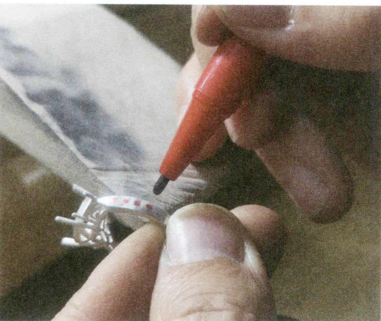
- Use an oil pen to mark the stone setting position on the tube ring, then use a bow saw or round file to create shallow grooves on the tube ring, or use a flat file to flatten one end of the silver wire.
- Cut the welding pieces into small particles, ignite a torch, hold the cut wire with tweezers, heat it until red, dip it in a small amount of borax, and use the welding gun to melt the cut silver welding particles into a small bead. Use the silver wire coated with borax to pick it up, and add a small amount of flux powder, placing it in the shallow groove. Aim the welding gun flame at the connection point between the wire and the ring until it brightens red. The welding piece will melt into a liquid state under the action of the flux powder, borax, and high temperature, tightly welding the silver wire to the ring.
- Cut off any excess height according to the required height of the prongs. Adjust the distance between the prongs to match the size and dimensions of the stone.
- Boil the finished setting in alum water to clean it, then use a cup burs to round the prongs.
When welding the setting, the following issues must be noted:
- The spacing between the claws should be evenly distributed, and the claws should be firm and stable.
- During welding, the amount of solder should be manageable; too much solder will affect the overall shape of the workpiece, making subsequent processes difficult to handle, while too little will result in a weak weld.
- The thickness of the claws should be determined based on the size and dimensions of the stone; for example, a 2mm four-claw setting generally uses a 0.7mm silver wire for the claws; a 3mm four-claw setting generally uses a 0.8mm silver wire for the claws.
(4) Making the clasp tongue and clasp box for the chain.
For chain-type jewelry, it is necessary to make a clasp tongue and a clasp box, which should be adjusted for smooth opening and closing. Three concepts are explained here: clasp tongue, clasp box, and safe latch. All three are colloquial terms in the industry, where the clasp tongue refers to the metal spring piece used in box-type safe latch resembling a duck’s tongue; the clasp box refers to the box used for the clasp tongue; the safe latch refers to the clasp that secures the clasp box and tongue at the side of the clasp to prevent them from becoming detached (Figure 2-26).

Make the clasp tongue:
Select a silver sheet of a certain width, generally with a thickness of 0.5mm, fold it, then remove the burrs and sand holes from various parts of the silver sheet, and polish it to a shine before welding it onto the silver piece.
Make the clasp box:
At the other end of the silver Jewelry Master Mold, create a box shape with a silver sheet, then use a bow saw to open a recess as required, welding a stop piece at each end of the opening. Use a teeth burs to clean the burrs and sharp edges inside the box; use a small flat file and a small square file to smooth the opening.
Ayarlama:
This refers to adjusting the fit between the clasp tongue and the clasp box to ensure smooth operation. The basic process is:
- Insert the clasp tongue into the clasp box, taking an appropriate position at the center of the tongue.
- Form two silver pieces into a “T” shape and weld them together as required to create a button.
- Weld this button at the designated center position to form a pressable clasp tongue.
- Place the clasp tongue back into the clasp box for adjustment, allowing it to move freely in and out. However, it is important to note that the clasp tongue cannot be pulled out when the button is not pressed.
(5) The specific operational process for making hoop earrings.
For hook earrings it is necessary to create a tube (referring to the tube used for inserting the pin) and ear pins. The manufacturing process is as follows.
Making the tube:
Polish the cast earrings to achieve a smooth finish. Use a saw to cut the earrings at the designated location; use a small round file to create two semicircles on the cutting edges. Select a silver tube that meets the specifications and cut it into three sections. Use a file, sandpaper, etc., to remove the saw marks from the tube and weld it at the corresponding positions. Choose a silver wire that matches the hole position of the silver tube and insert it into the tube hole to serve as the movable part of the earring. Use a file and sandpaper to smooth and polish this part.
Making ear pins:
Use a saw to cut the other end of the earring and remove the excess part; Use a press machine to compress a silver sheet to the required thickness, then sew out two pieces with a saw and use a file to shape the sawed silver pieces into two semicircles that meet the size requirements; Use a welding gun to weld the filed semicircles onto the two cutting surfaces of the ear pin position, and weld a silver wire of the required size at the center of the semicircle at one end of the earring to serve as the ear pin; Depending on the size of the ear pin, create a hole of the appropriate specification on the semicircle at the other end using a drill and ball burs, and repair the hole with a teeth burs and diamond burs.
Issues to pay attention to when making ear pins: The distance between the two ends when the ear pin is inserted into the hole should be between 5mm. The hinge position should have a certain degree of flexibility, neither loose nor tight. The welding points of the ear pin position should not show any crooked or slanted phenomena.
2. Post-processing of the silver Jewelry Master Mold
2.1 Setting the stone position
After the shape, size, and quality of the silver Jewelry Master Mold are qualified, for jewelry set with gemstones, it is necessary to determine the stone position (Figure 2-27) and set the stone position (Figure 2-28) on the silver Jewelry Master Mold, and check the alignment of the gemstone with the set mounts. If they do not align, adjustments must be made to the setting mounts of the silver Jewelry Master Mold until the stone mounts meets the requirements.

Şekil 2-27 Standart Taş Konumu

Figure 2-28 Calibration Stone Position
2.2 Sprue (i.e., casting line)
The sprue is designed to leave a channel for the flow of molten metal during the casting process. In jewelry casting, the correct setting of the sprue is a fundamental condition for ensuring casting quality. Many defects in lost-wax casting are directly or indirectly caused by improper sprue settings, such as insufficient filling, shrinkage, and air holes, which are common defects.
In jewelry casting, since no riser is set to compensate for the shrinkage of the workpiece, the sprue serves as both a channel for the molten metal to fill the mold and must also undertake the task of compensating for the shrinkage of the solidifying molten metal in the mold. Therefore, the setting of the sprue must follow some basic principles.
The inlet sprue mouth should be circular to reduce surface area and lower cooling speed. The sprue must allow the molten metal to flow easily into the mold cavity and serve as a sufficient reservoir for the volume shrinkage caused by the solidification of the casting. The sprue should solidify later than the casting to avoid the formation of shrinkage cavities.
(1) Position of the sprue. The sprue should connect to the thickest part of the casting. While satisfying the requirements for filling and compensating for shrinkage, it should be placed in a position that minimally affects the surface finish.
(2) The number of sprue. The number of sprue varies, including single, double, and multiple. The quantity of sprue depends on the size of the workpiece and is directly related to its structure. For small workpieces with a certain order of wall thickness, a single sprue is generally used; for medium workpieces with dispersed main wall thickness points, double or even multiple sprue are often used, such as in typical medium-sized rings and large bracelets, to ensure complete filling and good shrinkage compensation. For branch sprue, it is important to ensure that the cross-sectional area of the main sprue is sufficient to provide enough molten metal to the secondary branch sprue.
(3) The shape of the sprue. For the same volume, the surface area of a cylindrical shape is smaller than that of a square shape, which can reduce the cooling rate and extend the solidification time of the sprue, making it easier for the molten metal to flow into the mold cavity. Additionally, circular sprue facilitate the smooth flow of the molten metal.
(4) The size of the sprue.The sprue must ensure that the mold cavity is filled and can serve as a sufficient metal pool to compensate for the volume shrinkage that occurs during the solidification of the casting. Therefore, the diameter of the sprue should not be less than the thickness of the workpiece, and the length of the sprue should be appropriate to ensure that the sprue solidifies later than the casting, avoiding the formation of shrinkage cavities and porosity.
(5) The connection method of the sprue to the workpiece. The sprue should connect to the workpiece with rounded corners, allowing the molten metal to fill smoothly and reducing the erosion of the mold wall. It is important to avoid necking at the connection point of the sprue, as this can cause blockage and affect the filling process of the molten metal.