En omfattande guide till smycken och produktionsteknik i kopparlegeringar
Bemästra smycken i kopparlegering: Tekniker, material och trender
Inledning:
Den här artikeln dyker ner i den fascinerande världen av smycken i kopparlegeringar och dess produktionsmetoder. Den är indelad i fyra huvudavsnitt:
1. Översikt: Lär dig om kopparns historia, egenskaper och dess roll i smyckestillverkning. Kopparlegeringar som mässing, brons och kupronickel framhävs för sin mångsidighet och skönhet.
2. Ren koppar och legeringar med hög kopparhalt: Upptäck de olika typerna av ren koppar, såsom syrefri koppar och mikrolegerad koppar, och hur de används i smycken för sin hållbarhet och unika färger.
3. Kopparlegeringar: Utforska populära legeringar som mässing (koppar-zink), brons (koppar-tenn) och kupronickel (koppar-nickel), som alla erbjuder distinkta färger, korrosionsbeständighet och bearbetbarhet för att tillverka fantastiska verk.
4. Produktionstekniker: Få insikter i avancerade metoder som gjutning med förlorat vax, stämpling och elektroformning, tillsammans med ytbehandlingar som förgyllning och polering för att skapa högkvalitativa, iögonfallande smycken.

healing armband i röd koppar
Innehållsförteckning
Avsnitt I Översikt
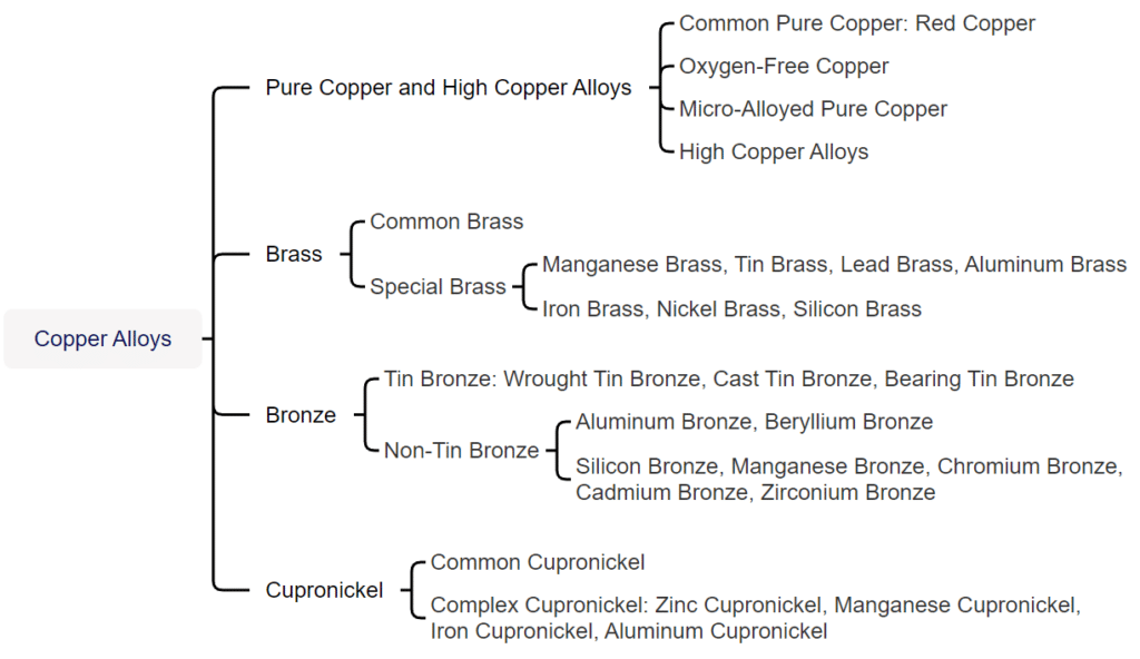
Koppar och kopparlegeringar kan delas in i två huvudkategorier baserat på produktionsprocessen: bearbetning och gjutning. Alla legeringar med prefixet Z i sin beteckning tillhör gjutlegeringar. Däremot klassificeras beteckningarna för bearbetad koppar och kopparlegeringar i Kina traditionellt i fyra kategorier: lila, gul, grön och vit. Bland dessa levereras lila kopparlegeringar alla i bearbetad form. Prefixet T representerar koden för lila koppar. Den första bokstaven H i pinyin för gul representerar gul koppar. På liknande sätt representerar Q brons, B representerar kupronickel, och de efterföljande kemiska elementsymbolerna och siffrorna representerar den nominella viktprocenten av de tillsatta elementen.
Koppar och kopparlegeringar kan delas in i två kategorier baserat på funktion: allmänt ändamål och specialändamål. Kopparlegeringar som används till smycken tillhör en typ av speciell kopparlegering med specifika krav på färgton, korrosionsbeständighet, gjutprestanda, bearbetningsprestanda, svetsprestanda och färgprestanda. De huvudsakliga koppar- och kopparlegeringarna som används i smyckestillverkning inkluderar ren koppar och legeringar med hög kopparhalt, tennbrons, mässing, zinkkopparnickel, imiterade guld-kopparlegeringar och imiterade silver-kopparlegeringar.
Avsnitt II Ren koppar och högkopparlegeringar
1. Ren popper och dess egenskaper
Ren koppar kan delas in i flera kategorier baserat på kemisk sammansättning: vanlig ren koppar, syrefri ren koppar och mikrolegerad ren koppar.
(1) Vanlig ren koppar
Vanlig ren koppar har en kopparmassfraktion på minst 99,7%, med mycket lite föroreningsinnehåll och har ett purpurrött utseende. Därför kallas den även purpurröd koppar. De huvudsakliga kvaliteterna av vanlig ren koppar är T1, T2 och T3. Enligt GB/T 5231-2001 visas den vanligt förekommande kemiska sammansättningen av vanlig ren koppar i tabell 2-1.
Tabell 2-1 Vanlig kemisk sammansättning av vanlig ren koppar (kvalitetsfraktionsenhet: %)
| Betyg | Cu+Ag | P | Bi | Sb | Som | Fe | Ni | Pb | Sn | S | Zn | O | Summan av föroreningar |
| Inte mindre än | Inte mer än | ||||||||||||
| T1 | 99. 95 | 0.001 | 0.001 | 0.002 | 0.002 | 0.005 | 0.002 | 0.003 | 0.002 | 0.005 | 0.005 | 0.02 | 0.05 |
| T2 | 99. 90 | - | 0.001 | 0.002 | 0.002 | 0.005 | - | 0.005 | - | 0.005 | - | - | 0.1 |
| T3 | 99. 70 | - | 0.002 | - | - | - | - | 0.01 | - | - | - | - | 0.3 |
| (Liu Ping, 2007; Wang Biwen, 2007; Tian Rongzhang och Wang Shitang, 2002; Nationella tekniska kommittén för standardisering av icke-järnmetaller, 2012) | |||||||||||||
Tabell 2-2 Fysikaliska egenskaper hos vanlig ren koppar
| Föreställningsnamn | Numeriskt värde | Föreställningsnamn | Numeriskt värde |
|---|---|---|---|
| Gittertyp | Ansiktscentrerad kubisk | Elektronisk konfiguration | Är2 2 sekunder2 2P6 3 sekunder2 3P6 3d10 4s1 |
| Atomvikt | 63.54 | Resistivitet | 0,016 73 Ω·m |
| Atomradie | 0,157 nm | Värmeledningsförmåga (273–373 K) | 399 W/(m² • K) |
| Jonisk radie | 0,073 nm | Temperaturkoefficient för resistans | 0,003 93/℃ |
| Densitet | 8. 92 g/cm²3 | Magnetisk susceptibilitet | -0,86 x 10⁻³/kg |
| Smältpunkt | 1083,4 ℃ | Specifik värmekapacitet | 0,39X10³J/(kg •℃) |
| Kokpunkt | 2 567 ℃ | Linjär expansionskoefficient | 17. 6X10⁻⁶/℃ |
| (Liu Ping, 2007; Wang Biwen, 2007; Tian Rongzhang och Wang Shitang, 2002; Nationella tekniska kommittén för standardisering av icke-järnmetaller, 2012) | |||
Koppar är en relativt inaktiv tungmetall med god korrosionsbeständighet. Den är stabil i torr luft vid rumstemperatur och kan producera svart kopparoxid vid upphettning. Röd koppar(I)oxid bildas om den kalcineras ytterligare vid höga temperaturer. Efter att ha placerats i fuktig luft under en längre tid bildas långsamt ett lager av ärg (basiskt kopparkarbonat) på kopparns yta. Ärg kan förhindra ytterligare korrosion av metallen; dess sammansättning är variabel och den är löslig i salpetersyra och varm koncentrerad svavelsyra, något löslig i saltsyra och korroderar lätt av alkalier. I den elektrokemiska (metallaktivitetsserien) rankas koppar efter väte, så den kan inte ersätta väte från utspädda syror. Koppar kan dock långsamt lösas upp i luften i dessa utspädda syror. Koppar kan reagera med uppvärmd koncentrerad saltsyra och är lättlöslig i salpetersyra och oxiderande syror som varm koncentrerad svavelsyra. Koppar kan också reagera med järnklorid. Inom smyckesindustrin används ofta järnkloridlösning för att etsa koppar för att skapa olika dekorativa texturer och mönster.
De mekaniska egenskaperna hos vanlig ren koppar är nära relaterade till dess tillstånd, vilket visas i tabell 2-3.
Tabell 2-3 Mekaniska egenskaper hos vanlig ren koppar i olika tillstånd
| Prestanda | Bearbetning av koppar | Returkoppar | Gjutning av koppar |
|---|---|---|---|
| Elastisk gräns/ MPa | 280 ~ 300 | 20 ~ 50 | - |
| Sträckgräns / MPa | 340 ~ 350 | 50 ~ 70 | - |
| Draghållfasthet/ MPa | 370 ~ 420 | 220 ~ 240 | 170 |
| Förlängningshastighet / % | 4 ~ 6 | 45 ~ 50 | - |
| Krympningshastighet/ % | 35 ~ 45 | 65 ~ 75 | - |
| Brinellhårdhet / HB | 1 100 ~ 1 300 | 350 ~ 450 | 400 |
| Skjuvhållfasthet/ MPa | 210 | 150 | - |
| Slagseghet/J·cm-2 | - | 16 ~ 18 | - |
| Tryckhållfasthet / MPa | - | - | 1570 |
| Upprörande förhållande/ % | - | - | 65 |
| (Liu Ping, 2007; Wang Biwen, 2007; Tian Rongzhang och Wang Shitang, 2002; Nationella tekniska kommittén för standardisering av icke-järnmetaller, 2012) | |||
(2) Syrefri ren koppar
Syrefri ren koppar är ren koppar med betydligt reducerad syrehalt som uppnåtts genom olika raffineringsmetoder. Enligt GB/T5231 delas syrefri koppar in i flera kvaliteter: noll, ett och två kvaliteter av syrefri koppar, med motsvarande koppar- och syrehalt som visas i tabell 2-4. Syrefri koppar uppvisar inte väteförsprödning och har hög elektrisk ledningsförmåga, god bearbetnings-, svets-, korrosionsbeständighet och lågtemperaturprestanda. Syrefri koppar föredras generellt vid framställning av tillsatsmaterial av guld- och silverlegeringar för att minska föroreningar i fogen.
Tabell 2-4 Krav för syrehalt i syrefri koppar
| Betyg | Kod | Koppar + silver ≥ | Syre≯ |
|---|---|---|---|
| Nr 0 syrefri koppar | TU0 | 99. 99 | 0. 0005 |
| Nr 1 syrefri koppar | 99. 97 | 0.002 | |
| Nr 2 syrefri koppar | TU2 | 99. 95 | 0.003 |
| (Nationella tekniska kommittén för standardisering av icke-järnmetaller, 2012) | |||
(3) Mikrolegerad ren koppar
Mikrolegerad ren koppar använder legeringsämnen som krom, zirkonium, silver, aluminium, fosfor, svavel och antimon, vilket effektivt kan förbättra prestandan hos ren koppar när det tillsätts i spårmängder. Mikrolegerad ren koppar har flera kvaliteter, såsom TUAg0.06, TUAg0.05, TUAg0.08, TUAg0.1, TUAg0.2, TUAg0.3, TUA10.12, TUZr0.15, TAg0.15, TAg0.1-0.01, TP3, TP4, TTe0.3, TTe0.5-0.008, TTe0.5-0.02, TZr0.15, etc. Med zirkoniummikrolegerad ren koppar som exempel visar tabell 2-5 dess mekaniska egenskaper, vilka är avsevärt förbättrade jämfört med vanlig ren koppar, och mjukningstemperaturen har nått 500 ℃.
Tabell 2-5 Mekaniska egenskaper hos zirkonium – mikrolegerad ren koppar QZr0,2
| Materialtillstånd | Draghållfasthet/MPa | Sträckgräns/MPa | Sträckningshastighet/% | Vickers-hårdhet/HV | Elasticitetsmodul/GPa |
|---|---|---|---|---|---|
| Släckt vid 980 ℃, åldrad vid 500 ℃ i 1 timme | 260 | 134 | 19. 0 | 83 | - |
| 900 ℃ släckning, 500 ℃ åldring 1 timme | 230 | 160 | 40. 0 | - | - |
| 900C uppvärmning 30 minuter kylning, kallbearbetning 90% | 450 | 385 | 3.0 | 137 | 136 |
| 980℃ uppvärmning 1 timme, 90% kallbearbetning, 400℃ åldring 1 timme | 492 | 428 | 10.0 | 150 | 133 |
| 900℃ kylning, kallbearbetning 90%, 400℃ åldring 1 timme | 470 | 430 | 10.0 | 140 | |
| (Liu Ping, 2007; Wang, B., 2007; Tian, RZ och Wang, ST, 2002; Nationella tekniska kommittén för standardisering av icke-järnmetaller, 2012) | |||||
2. Hög kopparlegering
Högkopparlegeringar, även kända som låglegerad koppar, avser kopparlegeringar som innehåller ett eller flera spårlegeringsämnen för att uppnå vissa speciella egenskaper. Kopparhalten är 99,3%~96% och kan inte klassificeras i någon kopparlegeringsgrupp för bearbetade produkter. För gjutna produkter bör kopparhalten vara större än 94%, vilket kan tillsättas för att erhålla vissa egenskaper.
Fastlösningsförstärkning och utskiljningsförstärkning är viktiga förstärkningsmetoder för kopparlegeringar. Vanliga legeringselement inkluderar Cr, Zr, Ti, Si, Mg, Te, etc. Deras löslighet i koppar minskar kraftigt med minskande temperatur. Dessa element utskiljs i fast tillstånd som rena ämnen eller metallföreningar, vilket resulterar i fastlösningsförstärkning och utskiljningsförstärkning. Det amerikanska gjuteriets höga kopparlegeringskvaliteter inkluderar C81300~C19600 och de bearbetade höga kopparlegeringskvaliteterna från C16200 till C19600. I den nyligen reviderade GB/T5231-2012 "Grades and Chemical Composition of Processed Copper and Copper Alloys" listar Kina höga kopparlegeringskvaliteter som TTi3.0 – 0.2, TNi2.4 – 0.6 – 0.5, TPb1.0, TCr1 – 0.18, TCr0.3 – 0.3, TCr0.5 – 0.1, TCr0.7, TCr0.8, TCr1 – 0.15.
3. Processprestanda för ren koppar och legeringar med hög kopparhalt
(1) Smältprocessen
Ren koppar och legeringar med hög kopparhalt absorberar väte och syre under gjutningsprocessen, vilket leder till porositet och oxidationsinneslutningar som påverkar gjutgodsets ytkvalitet. Halten av väte och syre är nära relaterad till materialets temperatur. Tabell 2-6 visar vätelösligheten i koppar vid olika temperaturer.
Tabell 2-6 Löslighet av väte i koppar vid 0,1 MPa (Nie Xiaowu, 2006)
| Temperatur /℃ | 400 | 500 | 600 | 700 | 800 | 900 | 1000 | 1100 | 1200 | 1300 | 1400 | 1500 |
|---|---|---|---|---|---|---|---|---|---|---|---|---|
| Löslighet /cm3 • (100 g koppar)-1 | 0.06 | 0.16 | 0. 3 | 0.49 | 0. 72 | 1.08 | 1.58 | 6.3 | 8. 1 | 10.9 | 11.8 | 13.6 |
Syre löses inte upp i koppar och bildar spröda föreningar med hög smältpunkt, Cu2O med koppar. När syrehaltig koppar kondenserar, utfälls syre som ett eutektikum (Cu+Cu2O), fördelat längs korngränserna. Den eutektiska temperaturen är mycket hög (1066 ℃) och påverkar inte den termiska deformationsprestanda, men den är hård och spröd, vilket gör kalldeformation svår och leder till "kallsprödhet" i metallen. När syrehaltig koppar glödgas i en vätgas- eller reducerande atmosfär sker "vätgasförsprödning". Kärnan i "vätgasförsprödning" är att under glödgning penetrerar vätgas eller den reducerande atmosfären lätt kopparen och reagerar med syret i CuO för att bilda vattenånga eller CO2Därför måste tydliga processspecifikationer upprättas och implementeras under smältning.
Ren koppar kan smältas med hjälp av en reflektionsugn eller induktionsugn med kärna. Under smältning i en reflektionsugn kan täta göt erhållas genom raffineringsprocesser med järn- eller kopparformar för gjutning, och halvkontinuerlig eller kontinuerlig gjutning kan också utföras med hjälp av en hållugn. Följande processflöde kan användas för induktionssmältningsprocessen.
① Förvärm först degeln till en mörkröd färg, tillsätt sedan ett lager torrt träkol eller täckmedel (63% borax + 37% krossat glas) med en tjocklek av cirka 30~50 cm i botten av degeln, följt av hörnrester, spillblock och stavmaterial, och slutligen tillsätt ren koppar.
② De tillsatta legeringselementen kan förvärmas på ugnsplattformen, och det är strängt förbjudet att tillsätta kalla material till den smälta metallen. Laddningen bör omröras ofta under hela smältprocessen för att förhindra bryggbildning.
③ Efter att legeringen har smält helt genom uppvärmning, när temperaturen når 1200~1250 ℃, tillsätt fosforkoppar-deoxideringsmedel, vilket motsvarar 0,3%~0,4% av den smälta legeringens vikt. Fosfor reagerar med koppar(I)oxid enligt följande:
5Cu2O + 2P = P2O5 + 10 Cu
Cu2O + P2O5 = 2CuPO3
Den genererade gasen P2O5 Utsläpp från legeringen och kopparfosfat kan flyta på ytan, vilket möjliggör borttagning av slagg för att uppnå syftet med deoxidation. Dessutom krävs kontinuerlig omrörning under deoxidationsprocessen.
④ Slutligen avlägsnas slaggen och legeringsvätskans hälltemperatur är vanligtvis 1150 ℃ ~ 1230 ℃.
(2) Processeringsteknik
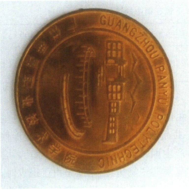
Ren koppar och högkopparlegeringar har utmärkta kall- och varmbearbetningsegenskaper. De kan bearbetas med traditionella trycktekniker, såsom sträckning, valsning, djupdragning, bockning, precisionspressning och spinning. Figur 2-2 är ett exempel på ett präglat smyckesämne av rent koppar. Under varmbearbetning bör värmemediet kontrolleras till 380~650 ℃. Glödgningstemperaturen på 800~900 ℃ kan väljas mellan för vanlig ren kopparbearbetning, varmbearbetningstemperaturen på 360 ℃ kan väljas, och den typiska mjukningstemperaturen är cirka. För högkopparlegeringar har mjukningstemperaturen ett större samband med dess kemiska sammansättning, såsom Cr- och Zr-legeringar med högkopparlegering (Cr0,25-0,65, Zr0,08-0,20), och dess mjukningstemperatur kan nå 550 ℃. Vid svetsning är ren koppar och högkopparlegeringar enkla för tennsvetsning och lödning, gasskyddad bågsvetsning, blixtsvetsning, elektronstrålesvetsning och gassvetsning.
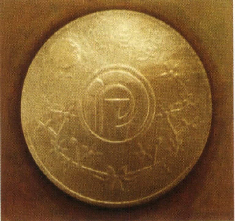
Figur 2-3 Kopparelektrod för stansning av smyckesformar
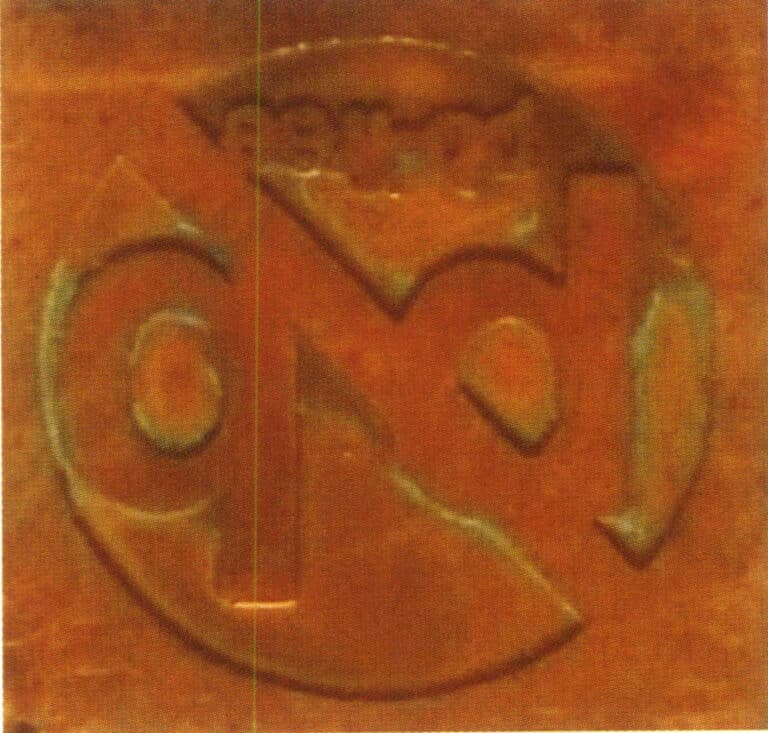
Figur 2-4 Smycken av ren koppar tillverkade med etsningsprocessen
Avsnitt III Kopparlegeringar
På grund av ren koppars dåliga mekaniska egenskaper och gjutegenskaper är de flesta kopparmaterial som används för populära smycken kopparlegeringar. Det finns många kategorier av kopparlegeringar, och för närvarande finns det inga specifika tekniska standarder för kopparlegeringar som används i smycken, både nationellt och internationellt. Industriella kopparlegeringskvaliteter används vanligtvis, och tillämpningen är ganska kaotisk, vilket påverkar produktkvaliteten. Därför behöver kopparlegeringar för smycken ytterligare standardisering. Kopparlegeringar för smycken är inte helt desamma som industriella kopparlegeringar och har unika krav.
(1) Legeringen måste uppfylla användningskraven för smycken. Den bör ha vissa mekaniska egenskaper, uppfylla hårdhetskraven, ha god korrosionsbeständighet, inte ha tendens till spänningskorrosion och ha vissa färger etc.
(2) Legeringen bör uppfylla olika processkrav, inklusive: ① God gjutprestanda. Kopparlegeringen bör ha god fluiditet och minimal krympning vid stelning vid tillverkning av ornament med hjälp av förlorad vaxgjutning. ② Svetsprestanda. Den bör inte lätt orsaka sprickor, oxidation, gasabsorption och färgskillnader under svetsning. ③ Bearbetbarhet. Hårdheten bör vara måttlig; om den är för hög kommer verktygsslitaget att bli betydande, och det blir svårt att uppnå en hög ytljushet om den är för låg. ④ Ytbehandlingsprestanda. De flesta kopparornament kräver ytbehandling, vilket bör underlätta färgning och korrosionsskydd med god färgkvalitet.
Kopparlegeringar som används till smycken inkluderar huvudsakligen flera typer, såsom mässing, kopparnickel och brons.
1. Mässing
1.1 Typer av mässing
Mässingens sammansättning kan delas in i två huvudkategorier: enkel mässing och specialmässing.
(1) Enkel mässing
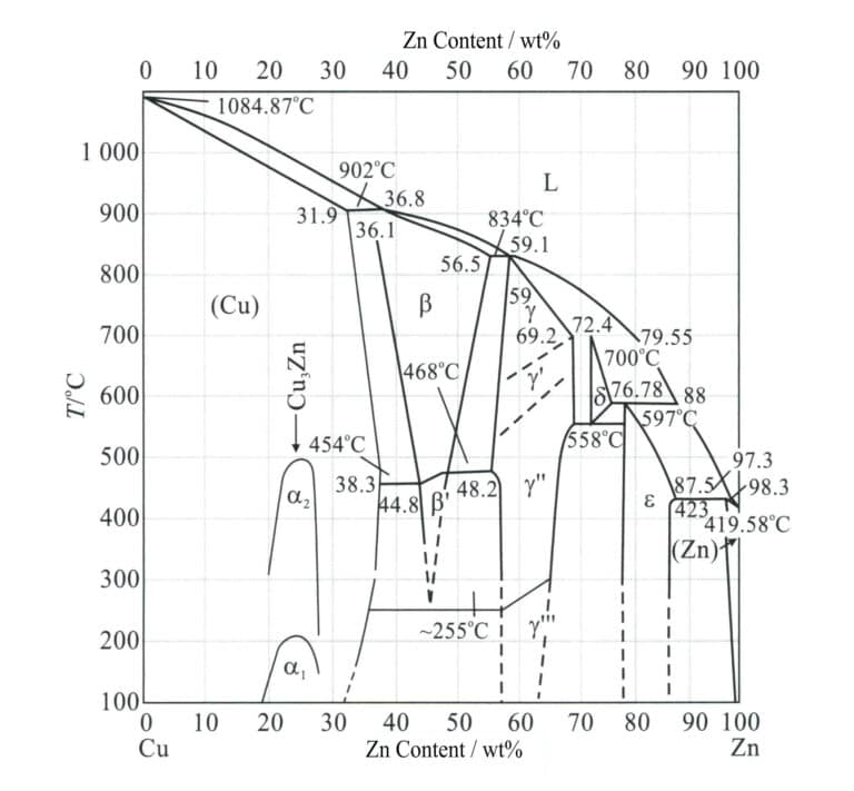
Enkel mässing är en binär legering bestående av koppar och zink, där zinkens roll i mässing huvudsakligen är att öka hållfastheten, justera färgen och förbättra gjutprestanda. Det finns tre vanliga jämviktsmikrostrukturer för binär mässing (Figur 2-5): när zinkhalten är lägre än 38% är det enfas α; när zinkhalten är 38%~47% är det α+β; när zinkhalten är 47%~50% är det enfas β och kallas finmässing, α+β-mässing och β-mässing. När zinkhalten överstiger 39% blir legeringen hård och spröd, vilket påverkar dess användningsområde. Därför överstiger kopparhalten i vanlig mässing som används för smycken i allmänhet 60%.
Tabell 2-7 Vanliga mässingskvaliteter och kemisk sammansättning
| Serienummer | Betygsnummer | Kemisk sammansättning/% | |||||
|---|---|---|---|---|---|---|---|
| Cu | Fe | Pd | Ni | Zn | Totala föroreningar | ||
| 95.0 ~ 97. 5 | 0.10 | 0.03 | 0.5 | Marginal | 0.2 | ||
| 2 | H90 | 88. 0 ~ 91.0 | 0.10 | 0.03 | 0.5 | Marginal | 0.2 |
| 3 | H85 | 84. 0 ~ 86. 0 | 0.10 | 0.03 | 0.5 | Marginal | 0.3 |
| 4 | H80 | 79. 0 ~ 81.0 | 0.10 | 0.03 | 0.5 | Marginal | 0.3 |
| 5 | H70 | 68. 5 ~ 71. 5 | 0.10 | 0.03 | 0.5 | Marginal | 0.3 |
| 6 | H68 | 67.0 ~ 70.0 | 0.10 | 0.03 | 0.5 | Marginal | 0.3 |
| 7 | H65 | 63. 5 ~ 68. 0 | 0.10 | 0.03 | 0.5 | Marginal | 0.3 |
| 8 | H63 | 62.0 ~ 65.0 | 0.15 | 0.08 | 0.5 | Marginal | 0.5 |
| 9 | H62 | 60. 5 ~ 63. 5 | 0.15 | 0.08 | 0.5 | Marginal | 0.5 |
| 10 | H59 | 57. 0 ~ 60. 0 | 0.30 | 0.5 | 0.5 | Marginal | 1.0 |
| (Liu Ping, 2007; Wang Biwen, 2007; Tian Rongzhang och Wang Shitang, 2002; Nationella tekniska kommittén för standardisering av icke-järnmetaller, 2012) | |||||||
Tabell 2-8 Ytfärger på vanlig mässing
| Betyg | Kopparhalt /wt% | Zinkhalt /wt% | Färg |
|---|---|---|---|
| H59 | 59 ~ 63 | Marginal | Ljusbrun - gyllene färg |
| H65 | 63 ~ 68. 5 | Marginal | Ren gul |
| H68, H70 | 68. 5 ~ 71. 5 | Marginal | Grön - Guld |
| H80 | 78. 5 ~ 81. 5 | Marginal | Gyllengul färg med en antydan till rött |
| H85 | 84 ~ 86 | Marginal | Brungul - gyllene |
| H90 | 89 ~ 91 | Marginal | Antik brons - guldfärg |
| H96 | 94 ~ 96 | Marginal | Rödbrun |

På grund av zinks mycket lägre elektrodpotential än koppar är legeringar benägna att utsättas för elektrokemisk korrosion i neutrala saltlösningar. Zinken med lägre potential löses upp, medan koppar kvarstår som en porös film på ytan och bildar mikrobatterier med mässingskompositionen under ytan, vilket gör att mässingen fungerar som en anod och accelererar korrosionen. Därför kräver mässingssmycken i allmänhet ytskyddsbehandlingar, såsom galvanisering med ett lager av ädelmetall eller applicering av en skyddande beläggning.
(2) Specialmässing
För att förbättra prestandan hos enkel mässing tillsätts 1%~5%-element som tenn, bly, aluminium, kisel, järn, mangan och nickel till legeringen, vilket bildar ternära, kvaternära eller till och med kvinära legeringar, kallade specialmässing eller komplexmässing, och mässingsnamnet prefixeras med de tillsatta elementen, såsom tennmässing, blykärmässing, aluminiummässing, manganmässing, aluminium-manganmässing, etc. Tenn kan hämma avzinkningskorrosion och förbättra mässingens korrosionsbeständighet. Bly har mycket låg löslighet i mässing och distribueras som fria partiklar i matrisen, vilket kan orsaka att spån går sönder och ger smörjning, vilket förbättrar materialets bearbetbarhet och slitstyrka. Aluminium spelar en solid lösningshärdande roll och bildar en skyddande aluminiumoxidfilm på ytan. Kiselmässing har hög korrosionsbeständighet, mekaniska egenskaper och gjutegenskaper samt stark spänningskorrosionsbeständighet. Nickelmässing har hög hållfasthet, seghet och korrosionsbeständighet och tål kall och varm plastbearbetning.
Mässingens komplexa struktur kan uppskattas baserat på "zinkekvivalentkoefficienten" för de element som tillsätts mässingen. Tillsats av en liten mängd andra legeringselement till koppar-zinklegeringen förskjuter vanligtvis bara fasområdet α/(α+β) i tillståndsdiagrammet Cu-Zn åt vänster eller höger. Till exempel, om man tillsätter 1%-tennekvivalenten till effekten av 2%-zink på de strukturella egenskaperna, innebär det att zinkekvivalenten för tenn är 2. Zinkekvivalenterna för olika legeringselement visas i tabell 2-9.
Tabell 2-9 Zinkekvivalenter för olika legeringselement
| Legeringselement | Kisel | Aluminium | Tenn | Leda | Järn | Mangan | Nickel |
|---|---|---|---|---|---|---|---|
| Zinkekvivalent | + 10 | + 6 | + 2 | + 1 | + 0. 9 | + 0. 5 | —1. 3 |
Därför motsvarar strukturen hos specialmässing vanligtvis strukturen hos vanlig mässing med ökat eller minskat zinkinnehåll. Fas α och fas β i komplex mässing är flerkomponents komplexa fasta lösningar med en större förstärkningseffekt. Däremot är fas α och fas β i vanlig mässing enkla fasta Cu-Zn-lösningar med en lägre förstärkningseffekt. Även om zinkekvivalenterna är jämförbara, skiljer sig egenskaperna hos en lösning med flera fasta ämnen från egenskaperna hos en enkel binär fast lösning. Därför är en liten mängd förstärkning av flera ämnen ett sätt att förbättra legeringens prestanda.
I specialmässing används en kopparbaserad imiterad guldlegering, känd som "sällsynt guld", flitigt i smycken och hantverk. Det är välkänt att guld har en lysande gyllene färg, god kemisk stabilitet, inte ändrar färg vid uppvärmning och har utmärkt oxidationsbeständighet, vilket gör det till ett etablerat val för dekorativa konstverk. Dess höga pris gör dock att billiga legeringar med liknande egenskaper används flitigt som ersättningsmedel. Under senare år har forskare, både nationellt och internationellt, konkurrerat om att utveckla kopparbaserade imiterade guldlegeringar för att ersätta guld och betydande framsteg har gjorts. Guldfärgen hos dessa material kan konkurrera med 16K~22K guld och har god korrosionsbeständighet och bearbetbarhet.
I kopparbaserade imiterade guldlegeringar används i allmänhet zink, aluminium, kisel och sällsynta jordartsmetaller som legeringselement, och effekterna av varje element på färg och oxidationsbeständighet är följande.
① Zink. Zn kan ändra kopparfärg från röd till gul, varvid huvudämnet bildar en gyllengul lyster. Zn kan förbättra legeringars missfärgningsbeständighet, och när Zn-halten ökar förbättras missfärgningsbeständigheten.
② Aluminium. Al är ett annat viktigt element som bidrar till legeringars färg. Aluminiumhalten påverkar legeringens färg avsevärt; när aluminiumhalten ökar minskar den huvudsakliga våglängden för ljus som reflekteras av legeringen, och nyansen ändras från röd till gul. En ytterligare ökning av aluminiumhalten försvagar märkbart legeringens gula nyans, vilket leder till en större färgskillnad mellan legeringen och rent guld. Legeringsstrukturen blir mer enhetlig när aluminium tillsätts mässingslegeringar. Det främjar bildandet av fas β, vilket hjälper till att minska avzinkningskorrosion i mässing och förbättrar anti-missfärgningsprestanda hos guldliknande legeringar i artificiell svett. Anledningen är att när aluminiumhalten är tillräckligt hög bildas en tät och fast fäst blandoxidskyddsfilm av koppar och aluminium på legeringens yta, och denna film har självläkande egenskaper när den skadas. Anti-missfärgningsprestanda är dålig när aluminiumhalten är för låg för att bilda en tät skyddande film.
③ Kisel. Si kan förbättra legeringars färg- och missfärgningsbeständighet. När 0,05%~2,50% Si tillsätts legeringen, ökar missfärgningsbeständighetstiden i artificiell svett med 50%~100% jämfört med samma legering utan Si; vid samma uppvärmningstemperatur ökar missfärgningsbeständighetstiden med 50%. Tillsats av Si kan också förbättra legeringens flytförmåga och slitstyrka.
④ Sällsynta jordartsmetaller. Att tillsätta sällsynta jordartsmetaller till mässingslegeringar kan förbättra legeringens ljusstyrka, förbättra dess färg och ge god slitstyrka, hårdhet och en färg som liknar guld och inte lätt bleknar. Inom smyckesindustrin kallas det vanligtvis för "sällsynt guldmaterial". Smycken tillverkade av sällsynt guldmaterial kan ha en färg som liknar 18K eller 20K guld, oxideras eller bleknar inte lätt, vilket gör det lämpligt för dagligt bruk och är billigt och blir ett material för att producera mer exklusiva imitationsguldsmycken.
Tabell 2-10 visar flera vanliga imiterade guld-kopparlegeringar, vilka kan klassificeras i det kopparbaserade legeringssystemet Cu-Al och Cu-Zn-systemet.
Tabell 2-10 Kemisk sammansättning av flera imiterade guldkopparlegeringar (kvalitetsfraktionsenhet: %)
| Betygsnummer | Aluminium | Tenn | Nickel | Kisel | Zink | Mangan | Sällsynta jordartsmetaller | Koppar | Anmärkningar |
|---|---|---|---|---|---|---|---|---|---|
| Cu - 12. 5Zn - 1Sn | 1.0 | 12. 5 | Resten | Rödguld | |||||
| Cu - 22Zn - 2Sn - 1P | 2.0 | 22.0 | Fosfor 1.0 | Resten | Ljus gyllengul | ||||
| Cu - 35Zn - 1,5Sn | 1.5 | 30.0 ~ 40.0 | Resten | Gyllengul | |||||
| Cu-6Al-15Zn-0,5Si | 6 | 0. 5 | 15 | Resten | |||||
| Subguld | 5.6 | 0. 26 | 0.70 | 92.6 | Analyserad sammansättning | ||||
| Subguld | 0.38 | 0.03 | 48.74 | 50.64 | Analyserad sammansättning | ||||
| Sällsynt jordartsmetallguld | 5 ~ 6 | 1 ~ 3 | 25 ~ 32 | 0. 8 ~ 1.5 | 0.1 | Resten | 18 kg guldfärg | ||
| Sällsynt jordartsmetallguld | 2 ~ 10 | 1 ~ 1.5 | 0. 05 ~ 2. 5 | 5 ~ 30 | 0. 05 ~ 0. 50 | Resten | 18 kg guldfärg | ||
| (Wang Biwen et al., 1998) | |||||||||
1.2 Mässingens egenskaper
(1) Korrosionsbeständighetsprestanda
Mässing har dålig korrosionsbeständighet i atmosfärer med hög temperatur, hög luftfuktighet och saltdimma och kan också uppleva "avzinkningskorrosion" i strömmande varmt havsvatten (zink löses upp först och lämnar en porös svampliknande ren koppar på arbetsstyckets yta). I fuktiga atmosfärer, särskilt de som innehåller ammoniak och SO42 , mässing utsätts för spänningskorrosion. Som nypolerade mässingsdekorationer blir ytan matt eller utvecklar mörka fläckar på vissa områden även efter att ha exponerats för luft under en tid. Därför kräver mässingsdekorationer i allmänhet ytfärgning eller galvaniseringsbehandling för att förbättra deras korrosionsbeständighet.
(2) Gjutningsprocessens prestanda
Mässings stelningsintervall är mycket litet, så den flytande metallens fluiditet är god, fyllnadsförmågan är utmärkt och tendensen till krymphåligheter är låg. Under smältning genererar zink ett högt ångtryck, vilket effektivt avlägsnar gaser från kopparvätskan, vilket gör det svårt för porer att bildas i mässing. Smälttemperaturen är lägre än tennbrons, och gjutning är relativt bekväm, vilket möjliggör enkel gjutning av små smycken. Det används också ofta för gjutning av kopparhantverk.
(3) Mekaniska egenskaper
På grund av den olika zinkhalten i mässing varierar även de mekaniska egenskaperna. För α-mässing ökar både σb och δ kontinuerligt när zinkhalten ökar. För (α+β)-mässing förbättras hållfastheten vid rumstemperatur kontinuerligt när zinkhalten ökar till cirka 45%. Om zinkhalten ökas ytterligare minskar hållfastheten kraftigt på grund av uppkomsten av en mer spröd fas γ (en fast lösning baserad på föreningarna Cu5 Zn8 ) i legeringsstrukturen. Zinkhaltens plasticitet vid rumstemperatur. Å andra sidan minskar (α+β)-mässing konsekvent med ökande zinkhalt. Därför har koppar-zinklegeringar med en zinkhalt som överstiger 45% inget praktiskt värde.
(4) Maskinbearbetbarhet
Enfas α-mässing (från H96 till H65) har god plasticitet och tål både kall och varm bearbetning. Enfas α-mässing är dock benägen att bli spröd vid medeltemperatur under varm bearbetning, såsom smide, och det specifika temperaturintervallet varierar beroende på Zn-halten, vanligtvis mellan 200 och 700 ℃. Därför bör temperaturen under varm bearbetning vara över 700 ℃. Den främsta orsaken till den medeltemperaturspröda zonen i enfas α-mässing är närvaron av två ordnade föreningar Cu.3 Zn och Cu9 Zn inom den ordnade fas α-regionen i legeringens Cu-Zn-system, som genomgår ordnad omvandling under uppvärmning vid medelhög till låg temperatur, vilket gör legeringen spröd; dessutom bildar spårmängder av skadliga föroreningar av bly och vismut eutektiska filmer med låg smältpunkt, fördelade vid korngränserna med koppar, vilket orsakar intergranulär sprickbildning under varm bearbetning. Praktiken visar att tillsats av spårmängder cerium effektivt kan eliminera sprödhet vid medelhög temperatur.
Tvåfasmässing (från H63 till H59) har, förutom den duktila fasen α i sin legeringsstruktur, en fast lösning β baserad på den elektroniska föreningen CuZn. Fasen har hög duktilitet vid höga temperaturer, medan fasen β' (ordnad fast lösning) är hård och spröd vid låga temperaturer. Därför bör (α+β)mässing smidas i varmt tillstånd. Β Mässing med en zinkhalt större än 46%~50% är hård och spröd på grund av sina egenskaper och kan inte bearbetas med tryck.
För relativt ömtåliga smycken bearbetas mässing vanligtvis med kallbearbetning. Mässingsmaterial som tråd, plåt och plattmaterial kan användas för att erhålla slutprodukten genom kallbearbetning. Under bearbetningen används naturligtvis mellanglödgning för att återställa mässingens plasticitet och förhindra sprickbildning på grund av deformationshärdning. Figur 2-7 visar ett karbinlås av mässing, och figur 2-8 visar ett armband av mässing. Mässingsplattor kan också användas för gravyr, med olika manuella tekniker som att trycka, borra, plocka, vrida och dra för att rista bilder på kopparplattans yta. De graverade bilderna elektropläteras sedan med ett skyddande lager av 24 karat guld, vilket resulterar i "guldskulpturmålningen".
(5) Svetsprestanda
Mässings svetsprestanda är god. För större hantverk används vanligtvis gassvetsning; för ömtåliga smycken används generellt fackelsvetsning.
(6) Poleringsprestanda
Mässingens skärprestanda är god och den tål operationer som korrigering, polering och ytbehandling. Smyckena kan poleras till en mycket blank yta med konventionella smyckesbehandlingsmetoder.
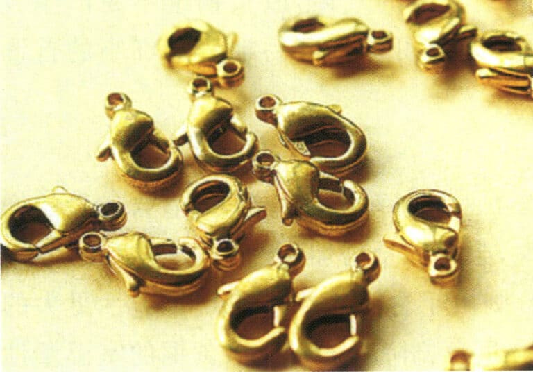
Figur 2-7 Hummerlås i mässingsbearbetad form
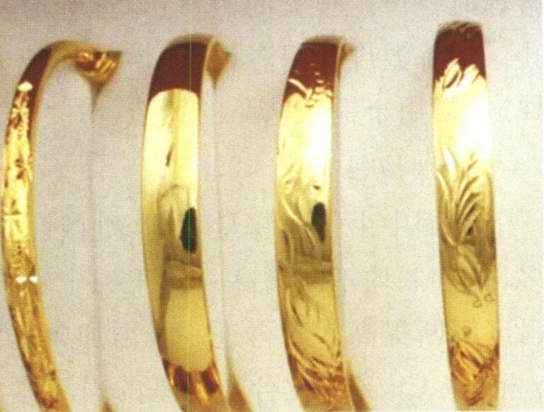
Figur 2-8 Mässingsarmband
2. Kopparnickel
2.1 Typer av kopparnickel
Kopparnickel kan delas in i tre kategorier: vanlig kopparnickel, komplex kopparnickel och industriell kopparnickel.
(1) Vanlig kopparnickel
Den binära koppar-nickel-legeringen kallas vanlig kupronickel och representeras vanligtvis av bokstaven B, där följande nummer anger kopparinnehållet, såsom B30, vilket indikerar en koppar-nickel-legering som innehåller Ni 30%. Modellerna inkluderar B0.6, B19, B25, B30, etc.
(2) Komplex kopparnickel
En komplex mässingslegering som innehåller element som mangan, järn, zink och aluminium kallas komplex mässing, representerad av bokstaven B, och legeringselementen, såsom BMn3-12, indikerar en koppar-nickel-mangan-legering som innehåller Ni3% och Mn12%. Det finns fyra modeller av komplex mässing.
- Ferro-kuppronickel. Modellerna inkluderar BFe5-1.5(Fe)-0.5(Mn), BFe10-1(Fe)-1(Mn), BFe30-1(Fe)-1(Mn). Mängden järn som tillsätts till ferrokuponickel överstiger inte 2% för att förhindra korrosionssprickbildning, och dess egenskaper inkluderar hög hållfasthet och avsevärt förbättrad korrosionsbeständighet, särskilt mot korrosion från rinnande havsvatten.
- Mangan-kuppronickel. Modellerna inkluderar BMn3-12, BMn40-1.5, BMn43-0.5. Mangan-kupronickel har en låg temperaturkoefficient, kan användas över ett brett temperaturområde, har god korrosionsbeständighet och har god bearbetbarhet.
- Zink-kuppronickel. Modellerna inkluderar BZn18-18, BZn18-26, BZn18-18, BZn15-12 (Zn) – 1,8 (Pb), BZn15-24 (Zn)-1,5 (Pb). Zink-kupronickel har utmärkta mekaniska egenskaper, enastående korrosionsbeständighet, god formbarhet vid kall och varm bearbetning, är lätt att skära och kan bearbetas till tråd, stänger och plattor, som används för tillverkning av precisionsdelar inom områden som instrument, mätare, medicintekniska produkter, dagliga förnödenheter och kommunikation.
- Aluminium-kuppronickel. Modellerna inkluderar BAl13-3 och BAl16-1.5. Blybrons är en legering som bildas genom att tillsätta aluminium till en koppar-nickellegering. Legeringens egenskaper är relaterade till förhållandet mellan nickel- och aluminiumhalten i legeringen, där de bästa egenskaperna uppnås när Ni:Al=10:1. Vanligt förekommande aluminium-kopparnickel är Cu6Ni1.5Al, Cu13Ni3Al, som huvudsakligen används inom varvsindustrin, elkraft, kemisk industri och höghållfasta korrosionsbeständiga komponenter inom dessa industrisektorer.
(3) Industriell kopparnickel
Industriell cupronickel är uppdelad i strukturell cupronickel och precisionsresistanslegering cupronickel (elektrisk cupronickel).
- Strukturell kopparnickel. Egenskaperna hos strukturmässing är goda mekaniska egenskaper och korrosionsbeständighet, med ett attraktivt utseende. Bland strukturmässing är de vanligaste B30, B10 och zinkmässing. Dessutom tillhör komplex mässing som aluminiummässing, järnmässing och niobmässing också strukturmässing. B30 har den starkaste korrosionsbeständigheten bland mässingar men är relativt dyr. Zinkmässing har producerats och använts i Kina sedan 1400-talet. Det är känt som "kinesiskt silver", det så kallade nickelsilveret eller tyskt silveret tillhör denna typ av zinkmässing. Zink kan lösas upp i stora mängder i koppar-nickel, vilket ger fasta lösningshärdande effekter och korrosionsbeständighet. Zinkkuppronickel kan bearbetas till precisionsdelar efter tillsats av bly. Således används det i stor utsträckning i instrument och medicintekniska apparater. Denna legering har hög hållfasthet och korrosionsbeständighet, god elasticitet, ett attraktivt utseende och är billig. Aluminiumet i aluminiumkuppronickel kan avsevärt förbättra legeringens hållfasthet och korrosionsbeständighet, och dess utfällningar kan också ge utskiljningshärdande effekter. Prestandan hos aluminiumkupronickel ligger nära B30:s och är billig, vilket gör det till en ersättning för B30.
- Kupronickel för precisionsmotståndslegeringar (elektrisk kupronickel). Kupronickel för precisionsresistanslegeringar (elektrisk kupronickel) har god termoelektrisk prestanda. BMn 3-12 mangankoppar, BMn 40-1,5 konstantan, BMn 43-0,5 kovar och ny konstantan med mangan istället för nickel (även känd som nickelfri mangankuppronickel, innehållande 10,8%~12,5% mangan, 2,5%~4,5% aluminium och 1,0%~1,6% järn) är mangankuppronickel med olika manganhalter. Mangankuppronickel har hög resistivitet och lågtemperaturresistivitetskoefficient, vilket gör den lämplig för produktion av standardresistanskomponenter och precisionsresistanskomponenter, och används vid tillverkning av precisionselektriska instrument, reostater, mätare, precisionsmotstånd, töjningsgivare och andra material.
2.2 En kort historia om kopparnickel
Uppfinningen av kopparnickel är en enastående prestation inom det antika Kinas metallurgiteknik. I det antika Kina kallades kopparnickel för "Gan". Den "Gamla Tang-boken • Avhandling om kläder" säger: "Endast oxar som drar vagnarna tillhörande förstklassiga tjänstemän får prydas med kopparnickel." Detta innebär att det under Tangdynastin föreskrevs att endast oxar tillhörande förstklassiga hovtjänstemän fick dekoreras med kopparnickel, vilket indikerar att kopparnickel var mycket värdefullt under den tiden. Folket i Yunnan uppfann och producerade kopparnickel, vilket gjorde dem till några av de tidigaste i Kina och världen, vilket är erkänt av den akademiska världen nationellt och internationellt. Den kopparnickel som producerades i det antika Yunnan var också den mest kända, känd som "Yun-kopparnickel".
De kupronickel-artefakter som tillverkades i det antika Kina såldes över hela landet och exporterades utomlands. Enligt forskning göts kupronickelmynt i Daxia-riket, beläget väster om Xinjiang, redan under Qin- och Han-dynastierna, och innehöll nickel upp till 20%. Baserat på deras form, sammansättning och de historiska förhållandena vid den tiden är det mycket troligt att de transporterades från Kina. Under Tang- och Song-dynastierna exporterades kinesisk nickel-kupronickel redan till den arabiska regionen, där perserna kallade kupronickel för "kinesisk sten". Efter 1500-talet såldes kinesisk kupronickel över hela världen och fick stor hyllning. Den exporterades genom Guangzhou och såldes i Europa av British East India Company. Den engelska termen "Paktong" eller "Petong" är en translitteration av den kantonesiska "cupronickel", som betyder kupronickel från Kina, och hänvisar specifikt till den koppar-nickel-legering som produceras i Yunnan.
Under 1600- och 1700-talen introducerades nickel, kupronickel, i stor utsträckning i Europa och betraktades som ett värdefullt föremål. Det kallades "kinesiskt silver" eller "kinesisk kupronickel", och det påverkade den moderna kemiska industrin i västvärlden avsevärt. Efter 1500-talet började vissa europeiska kemister och metallurger studera och imitera kinesisk kupronickel.
År 1823 lyckades de tyska bröderna Heineger replikera Yunnan-kuppronickel. Strax därefter började västvärlden storskalig industriell produktion och döpte om denna legering till "tyskt silver" eller "nickelsilver", medan den äkta Yunnan-kuppronickeln blev okänd. Efter att västvärlden framgångsrikt replikerat Yunnan-kuppronickel minskade exportmängden av kinesisk kopppronickel avsevärt. I slutet av 1800-talet hade tyskt silver ersatt kinesisk kopppronickel på den internationella marknaden, vilket ledde till en nedgång för Kinas kopppronickelbrytning och metallurgi.
2.3 Användningen av kopparnickel i smycken
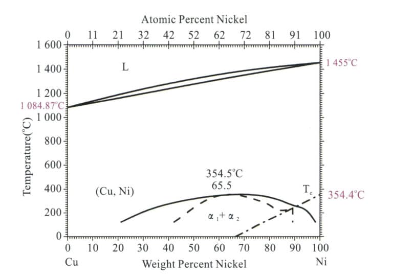
När nickel smälts till koppar, och halten överstiger 16%, blir den resulterande legeringen lika vit som silver. Ju högre nickelhalt, desto vitare färg. Att kombinera ren koppar och nickel kan också avsevärt förbättra styrka, korrosionsbeständighet och hårdhet. Därför, även om kopparns mekaniska och fysikaliska egenskaper är relativt goda, har den ett attraktivt utseende, är korrosionsbeständig och har utmärkt djupdragningsprestanda, vilket gör det till ett utmärkt material för smycken. Det används ofta i stor utsträckning för att tillverka imitationssilver och imitationsplatina, med hårdhet och glans mycket nära silversmycken, men till ett mycket lägre pris.
I smycken gjorda av kopparnickelmaterial är zinkkopparnickel den vanligaste, med typiska kvaliteter och sammansättning som visas i tabell 2-11 och egenskaperna hos zinkkopparnickel som visas i tabell 2-12.
Tabell 2-11 Kemisk sammansättning av inhemsk zinkkoppronickel
| Betyg | Kemisk sammansättning /% | ||||||||||||
|---|---|---|---|---|---|---|---|---|---|---|---|---|---|
| Ni+Co | Fe | Mn | Zn | Pb | Si | P | S | C | Mg | Sn | Cu | Totala föroreningar | |
| BZn 18-18 | 16. 5 ~ 19. 5 | 0.25 | 0.50 | Marginal | 0.05 | - | - | - | - | - | - | 63. 5 ~ 66. 5 | - |
| BZn 18-26 | 16. 5 ~ 19. 5 | 0.25 | 0.50 | Marginal | 0.05 | - | - | - | - | - | - | 53. 5 ~ 56. 5 | - |
| BZn 15-20 | 13.5 ~ 16. 5 | 0.5 | 0.3 | Marginal | 0.02 | 0.15 | 0.005 | 0.01 | 0.03 | 0.05 | 0.002 | 62.0 ~ 65.0 | 0.9 |
| BZnl5-21-1.8 | 14. 0 ~ 16.0 | 0.3 | 0.5 | Marginal | 1. 5 ~ 2.0 | 0.15 | - | - | - | - | - | 60. 0 ~ 63.0 | 0. 9 |
| BZnl5 -24-1.5 | 12. 5 ~ 15.5 | 0.25 | 0. 05 ~ 0. 5 | Marginal | 1. 4 ~ 1. 7 | - | 0.02 | 0. 005 | - | - | - | 58. 0 ~ 60. 0 | 0.75 |
| (Liu Ping, 2007; Wang Biwen, 2007; Tian Rongzhang och Wang Shitang, 2002; Nationella tekniska kommittén för standardisering av icke-järnmetaller, 2012) | |||||||||||||
Tabell 2-12 Fysikaliska och mekaniska egenskaper hos zinkkuppronickel
| Prestanda | Legering | |
|---|---|---|
| BZnl5-20 | BZnl7-18-1.8 | |
| Flytande faspunkt / ℃ | 1 081.5 | 1 121.5 |
| Fastfaspunkt/℃ | - | 966 |
| Densitet ρ/ g·cm-3 | 8. 70 | 8.82 |
| Värmekapacitet c/J • (g·°C)-1 | 0.40 | - |
| 20-100 ℃ Linjär expansionskoefficient α/℃-1 | 16. 6X10⁻⁶ | - |
| Värmeledningsförmåga λ/W·(m·℃)-1 | 25 ~ 360 | - |
| Resistivitet ρ/μΩ·m | 0.26 | - |
| Resistanstemperaturkoefficient αR/℃-1 | 2X10⁻⁴ | - |
| Elasticitetsmodul E/GPa | 126 ~ 140 | 127 |
| Draghållfasthet σb/MPa | 380 ~ 450 mjukt tillstånd, 800 hårt tillstånd | 400 mjukt tillstånd, 650 hårt tillstånd |
| Förlängning δ/% | 35 ~ 45 mjukt tillstånd, 2 ~ 4 hårt tillstånd | 40 mjukt tillstånd, 2,0 hårt tillstånd |
| Sträckgräns σ0.2 /MPa | 140 | - |
| Brinellhårdhet HB | 70 mjukt tillstånd, 160 ~ 175 hårt tillstånd | - |
| Skärprestanda (jämför med HPb63-3)/% | - | 50 |
| (Liu Ping, 2007; Wang Biwen, 2007; Tian Rongzhang och Wang Shitang, 2002; Nationella tekniska kommittén för standardisering av icke-järnmetaller, 2012) | ||
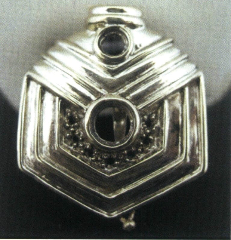
2.4 Utvecklingen av kopparnickelmaterial
Nickelkoppronickel har många utmärkta egenskaper som material för smycken, men det har också vissa nackdelar. Eftersom det viktigaste tillsatsämnet, nickel, är ett sällsynt material är priset på koppronickel relativt högt. Dessutom, på grund av den utbredda oron för nickels skadliga effekter i olika länder, kan produkter som är tillverkade för kontakt med mänsklig hud, såsom dragkedjor, glasögonbågar, mynt, bestick och smycken, orsaka allergiska hudreaktioner. Därför har nickel-koppronickel-material mött utmaningar de senaste åren, vilket gör utvecklingen av nya nickelfria koppronickel-legeringar särskilt viktig.
Hittills har merparten av forskningen om nickelfri kupronickel fokuserat på Cu-Mn-Zn-legeringen, och huvudrollerna för varje legeringselement är följande.
(1) Mangan
Mangan är det viktigaste tillsatsämnet i nickelfria kupronickellegeringar. Det kan minska de gula och röda komponenterna i färgen på kopparns yta, fungera som ett blekmedel eller blekningsmedel, vilket ändrar legeringens färg från färgad till färglös. Mangan kan förbättra legeringens mekaniska egenskaper genom att stärka den fasta lösningen. Att delvis ersätta zink med mangan kan förbättra åldringssprickförhållandena. Mangan kan undertrycka avdunstningen av zink under smältning och minska materialkostnaderna. Men om manganhalten överstiger 15% kommer legeringen att uppvisa en α+β flerfasstruktur, vilket leder till sämre bearbetningsprestanda. Mangan är skadligt för legeringens gjutningsprestanda; under smältning oxiderar mangan lätt för att bilda manganoxidinneslutningar med hög smältpunkt, vilka har en hög densitet och är svåra att flyta ut ur den smälta metallen, vilket gör det lätt för gjutgods att få inneslutningsdefekter. Dessutom ökar mangan legeringens krympningshastighet, vilket minskar dess fluiditet, och hög manganhalt kan försämra legeringens bearbetningsprestanda. Därför bör manganhalten, ur ett processprestandaperspektiv, inte vara för hög.
(2) Zink
Zink kan förbättra legeringars hållfasthet och hårdhet genom förstärkning i fast lösning, sänka legeringars smältpunkt, förbättra formningsprestanda och minska legeringars kostnad. När zinkhalten är för låg är förstärkningseffekten dålig; att öka zinkhalten kan förbättra förstärkningseffekten. Zink minskar dock kopparns korrosionsbeständighet avsevärt, särskilt när zinken överstiger 22%, vilket gör att legeringen omvandlas till en α+β-flerfasstruktur, vilket försämrar bearbetningsprestanda och är benägen för åldringssprickor orsakade av kvarvarande spänningar. När zinkhalten är lägre än cirka 30% minskar en ökning av zinkhalten den röda komponenten i färgen på Cu-Mn-Zn-legeringen samtidigt som den gula komponenten och ljusstyrkan ökar. Zink har också en viktig inverkan på legeringars färgstabilitet; när zinkhalten ökar minskar legeringens motståndskraft mot missfärgning i artificiell svett.
(3) Aluminium
Aluminium är ett av de viktigaste färgämnena i imiterade guldlegeringar. När aluminiumhalten ökar ökar ljusstyrkan och den gula komponenten i den ternära Cu-Zn-Al-legeringen, medan den röda komponenten minskar. Zinkekvivalentkoefficienten för aluminium är mycket hög; varje 1% aluminium motsvarar 6% zink, så α-fasregionen minskar avsevärt efter tillsats av aluminium. Aluminium kan bilda en tät oxidfilm på legeringens yta, vilket kan förbättra problem med åldringssprickor och avzinkningskorrosion i legeringen, och det producerar också förstärkning i fast lösning, vilket är fördelaktigt för att förbättra legeringens mekaniska egenskaper. När aluminiumhalten är för låg är förstärkningseffekten otillräcklig och inte tillräcklig för att motstå åldringssprickor. Men om dess innehåll överstiger 4% blir det svårt att rena den smälta metallen under legeringens smältning, och en komplex α+β-fasstruktur uppstår, vilket försämrar kallbearbetningsprestanda.
(4) Tenn
Tenns zinkekvivalentkoefficient är 2, så att tillsätta en liten mängd tenn har liten effekt på strukturen, och legeringen förblir enfasig. Tenn har en viss lösningsförstärkande effekt. Om dess innehåll överstiger en viss nivå är det dock benäget att bilda faser med låg smältpunkt vid korngränserna, vilket är skadligt för de mekaniska egenskaperna. En liten mängd tenn har också liten effekt på färgen på Cu-Mn-Zn-legeringen; dess huvudsakliga roll är att bilda en SO2-skyddsfilm på legeringens yta, vilket avsevärt kan förbättra legeringens motståndskraft mot missfärgning. Tenn kan öka legeringens fluiditet och förbättra gjutprestanda, men det ökar legeringens kostnad.
(5) Sällsynta jordartsmetaller
Spårmängder av det sällsynta jordartsmetallen cerium kan förfina kornstorleken, förbättra legeringens draghållfasthet och töjning samt förbättra legeringens kallbearbetningsprestanda.
By comprehensively utilizing these elements, researchers at home and abroad have developed a series of multi-element nickel-free white Cu-Mn-Zn alloys, such as Cu- 12Mn -8Zn – 1Al – 0.04%Ce, Cu – 15Mn – 15Zn – 1Al, Cu – 20Mn – 20Zn – 0.3Al – 0.2Sn – 0.05Mg, etc.
3. Brons
De andra kopparlegeringarna kallas brons, förutom mässing och kupronickel. Brons hänvisar generellt till legeringen av rödkoppar med tenn, bly och andra kemiska element, uppkallad efter sin blågrå färg. Brons delas in i tennbrons och icke-tennbrons, där tennbrons är den äldsta konstnärliga gjutlegeringen i historien. Icke-tennbrons är en ny typ av brons som utvecklats i modern tid, som använder element som kisel och aluminium för att ersätta det dyrare tennet samtidigt som det ytterligare förbättrar vissa egenskaper hos tennbrons. Den största fördelen med brons är dess utmärkta slitstyrka, och det har också hög korrosionsbeständighet i ånga, havsvatten och alkaliska lösningar, vilket är en viktig anledning till att antika bronskonstverk har bevarats perfekt än idag. Dessutom har brons en lägre smältpunkt, bättre gjutprestanda och goda mekaniska egenskaper.
Brons som används för konstnärliga gjutningar inkluderar vanligtvis tennbrons, kiselbrons, aluminiumbrons etc.
3.1 Tennbrons
Tennbrons är en forntida kopparlegering inom gjutkonsten med en historia på över 5000 år. De flesta av den kinesiska nationens forntida gjutkonstskatter gjöts i tennbrons, såsom Simuwu Ding från Shangdynastin, rituella kärl från vår- och höstperioden samt perioderna under krigande stater, och bianzhong (bronsklockor), bland andra.
(1) Tennbronsens struktur och prestandaegenskaper
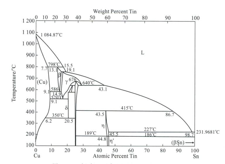
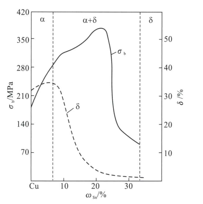
Tennbrons är baserat på en koppar-tennlegering; diagrammet (Figur 2-11) är det binära Cu-Sn-fasdiagrammet och utgår från α-, β-, γ- och δ-faserna, bland vilka α-fasen är en substitutionell fast lösning av tenn löst i ren koppar, med ett ytcentrerat kubiskt gitter, vilket bibehåller den goda plasticiteten hos ren koppar. Β-fasen är en fast lösning baserad på den elektroniska föreningen Cu.5 Sn, med ett kroppscentrerat kubiskt gitter, existerar vid höga temperaturer och sönderdelas under kylningsprocessen. Γ-fasen är en fast lösning baserad på CuSn, med egenskaper som liknar β-fasen. δ-fasen är en fast lösning baserad på den elektroniska föreningen Cu.31 Sn8 , med ett komplext kubiskt gitter, som existerar vid rumstemperatur, är hårt och sprött.
(2) Legeringselementens roll i tennbrons
① Zink. Att tillsätta zink till tennbrons kan minska kristallisationstemperaturintervallet för tennbrons, förbättra legeringens fluiditet och minska tendensen att producera krymphåligheter. Dessutom har zink ett relativt högt ångtryck under smältning, och den bildade zinkångan kan förhindra oxidation av koppar- och tennelement, rengöra legeringen och minska tendensen att bilda porer. Effekten av zink på tennbrons struktur och egenskaper liknar tenn, där tillsatsen av 2%-zink motsvarar rollen av 1%-tenn. Priset på zink är dock mycket lägre än priset på tenn, så zink kan användas för att ersätta tenn för att minska kostnaderna. Om zinkhalten överstiger 5% kan det göra mönstren otydliga, öka känsligheten för korrosion och göra det svårt att skapa ett elegant grönt yttre lager.
② Bly. Bly har en mycket låg hårdhet och distribueras i partikelform i tennbrons, vilket förbättrar legeringens slitstyrka och underlättar bearbetningen av brons. Samtidigt förbättrar blyets låga smältpunkt tennbronsens flytbarhet. Under stelningen ackumuleras bly i mellanrummen mellan dendriter, vilket minskar krympning och förhindrar läckage, där den bästa antiläckageeffekten generellt uppnås vid en blyhalt på cirka 5%. Bly har en relativt hög specifik vikt i brons, och för mycket bly kan orsaka gravitationell segregation, så det är viktigt att röra om den blyhaltiga tennbronsen före hällning och att använda vattenkylning eller metallformar för att påskynda kylningen och förhindra segregation.
③ Nickel. Nickel är oändligt lösligt i bronsfasta lösningar, vilket främjar utvecklingen av α-dendriter. Därför kan tillsats av en liten mängd nickel minska segregeringen av tenn och bly. Tillsats av 1%~2% nickel kan förfina kornen, förbättra mekaniska egenskaper, korrosionsbeständighet och termisk stabilitet samt förbättra bronsens gjutprestanda. En större mängd nickel kommer att göra att bronset ser vitare ut.
④ Järn. Järns huvudsakliga funktion liknar nickels; det kan förfina korn, öka styrkan och förbättra färgprestanda. Halten måste dock kontrolleras under 5%; annars kommer det att göra bronsen spröd och minska korrosionsbeständigheten.
⑤ Aluminium. I tennbrons är aluminium en skadlig förorening som gör färgning svår. Så länge 0,5% aluminium är närvarande ändras ytan från mörkröd till gyllengul och sedan till silvervit. Aluminium kan dock förbättra hållfasthet, korrosionsbeständighet och gjutprestanda i blyfri brons.
⑥ Fosfor. 0,03%~0,06% fosfor måste tillsättas tennbrons för att deoxidera det och förbättra gjutprestanda; för stora mängder kan lätt producera en spröd fas av Cu3 P och minska färgeffekter.
⑦ Kisel. Att tillsätta kisel till brons försämrar dess mekaniska egenskaper och gjutegenskaper, men kan öka korrosionsbeständigheten. Kisel ger ytan en mörkröd till brun färg, ibland lila, på grund av en mycket tät SiO2.2 film som täcker ytan, vilket gör färgning svår.
Tennbrons har ett vackert utseende och utmärkta bearbetningsegenskaper. Det har använts flitigt inom gjutning sedan antiken. Tabell 2-13 listar några vanligt förekommande tennbronsmaterial för konstnärliga gjutningar.
Tabell 2-13 Tennbrons för konstnärliga gjutningar
| Namn, betyg | Huvudkemiska komponenter /% | Förorening /%≯ | Anmärkningar | ||||||||
|---|---|---|---|---|---|---|---|---|---|---|---|
| Sn | Zn | Pb | A1 | Cu | Sb | Fe | Al | Total | |||
| ZCuSn2Zn3 | 1.8 ~ 2.2 | 2.5 ~ 3.5 | Marginal | Kinas standard | |||||||
| ZCuSn3A12 | 2.5 ~ 3.5 | 1.5 ~ 3.5 | Marginal | Kinas standard | |||||||
| ZCuSnl2Mnl | 10 ~ 15 | 0. 15 ~ 0. 25 | 0. 2 ~ 0. 3 | Mn 1,0 ~ 1,25 | Marginal | Kinas standard | |||||
| ZCuSn5Zn5Pb5 | 4.0 ~ 6.0 | 4.0 ~ 6.0 | 4.0 ~ 6.0 | Marginal | Kinas standard | ||||||
| ZCuSn10Zn2 | 9.0 ~ 11.0 | 1.0 ~ 2.0 | Marginal | Kinas standard | |||||||
| BC1 | 2.0 ~ 4.0 | 8.0 ~ 12.0 | 3.0 ~ 7.0 | 79. 0 ~ 83. 0 | 2.0 | Japansk standard | |||||
| BC6 | 4.0 ~ 6.0 | 4.0 ~ 6.0 | 4.0 ~ 6.0 | 82. 0 ~ 87.0 | 2.0 | Japansk standard | |||||
| BC7 | 5.0 ~ 7.0 | 3.0 ~ 5.0 | 1.0 ~ 3.0 | 86. 0 ~ 90. 0 | 1.5 | Japansk standard | |||||
| G-CuSn5ZnPb | 4.0 ~ 6.0 | 4.0 ~ 6.0 | 4.0 ~ 6.0 | 84. 0 ~ 86. 0 | 0.3 | 0.3 | P0.05 | S0. 10 | Tysklands standard | ||
| C90300 | 7.5 ~ 9.0 | 3.0 ~ 7.0 | 86.0 ~ 89. 0 | 0.2 | 0.15 | 0. 005 | Si0. 005 | 1.76 | Amerikansk standard | ||
| (Tian Rongzhang och Wang Zhutang, 2002) | |||||||||||
Tennbrons används för gjutning av konstverk och tål höga temperaturer, hög luftfuktighet och exponering för kommunala avgaser (främst CO₂2, SÅ2, INGA gaser) och till och med surt regn. I normal atmosfär är korrosionshastigheten för tennbrons 0,001 mm/år; i kustatmosfären är den 0,002 mm/år; i industriell atmosfär är den 0,002~0,006 mm/år.
Stora gjutna konstverk utomhus kan spricka på grund av stress orsakad av solljus, temperaturskillnader och svetsning i en korrosiv atmosfär. Tennbrons har en låg tendens till spänningssprickbildning, vilket effektivt kan minska denna risk. Till exempel är Tian Tan Buddha i Hongkong tillverkad av 8% Sn och 4%, medan resten är koppar, gjuten och sammansvetsad, och färdigställdes 1989. Den har stått säkert på Lantau Islands Muk Yu Peak i Hongkong sedan dess.
3.2 Användningen av brons i hantverksornament
Due to the beautiful appearance and excellent processing performance of bronze, it has been widely used as a material for craft jewelry from ancient times to the present.
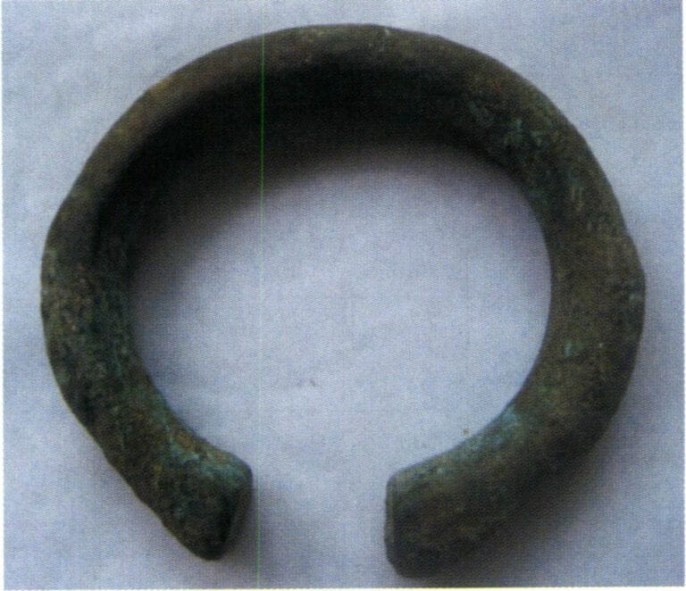
In ancient times, in addition to being widely used as utensils, it was also used for delicate and intricate ornaments, such as bronze bracelets from the Han Dynasty and bronze rings from the Liao Dynasty. Today, the application of bronze in crafts and jewelry has great development potential, especially with the improvement of economic levels, the rapid development of bronze casting, high market demand, a wide variety of products, and various methods of replication, imitation, and creation. It is widely used as urban sculptures, temple ritual vessels, Buddha statues, decorative paintings, and collectibles. In terms of jewelry, bronze is also used to make various ornaments and accessories. For example, the famous Greek fashion brand Folli Follie specializes in designing, manufacturing, and distributing jewelry, watches, and accessories. The company has launched the Precious Bronze series, combining bronze and silver. The necklaces, bracelets, and earrings are irregularly round, evoking a nostalgic feeling reminiscent of a land bathed in golden sunlight. The mix of different materials and the freshness of silver create beautiful curves. These luxurious treasures carry the brilliant characteristics of Folli Follie, exuding the elegance and beauty of true fashionistas.

Hong Kong Tian Tan Buddha (Bronze)
Liao Dynasty bronze ring
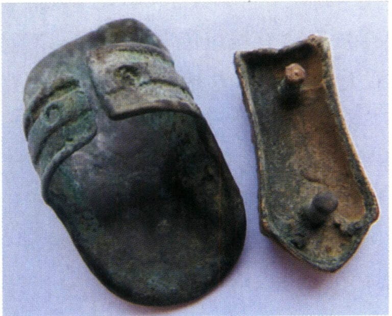
Bronze bracelet from the Han Dynasty
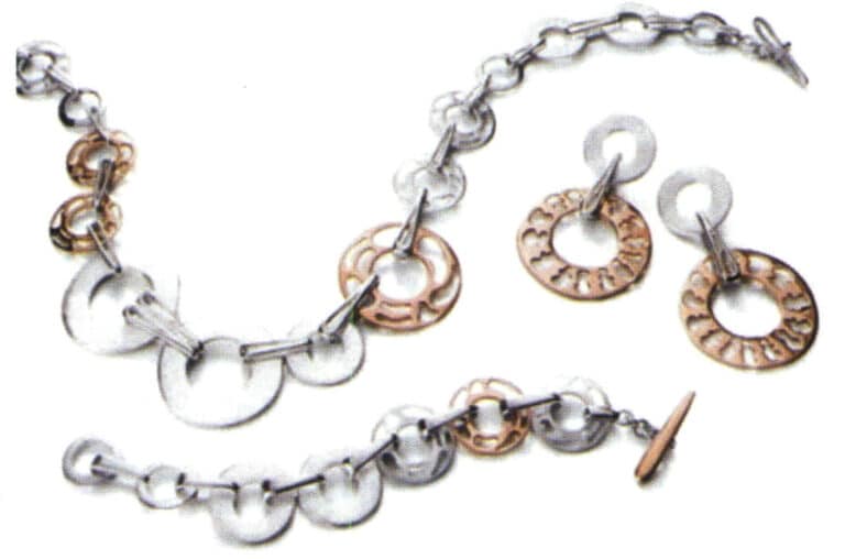
Folli Follie company's precious bronze jewelry (bronze + silver)
Copywrite @ Sobling.smycken - Anpassad smyckestillverkare, OEM och ODM smyckesfabrik
Section IV The Craftsmanship of Copper jewelry
1. The Lost Wax Casting Process for Copper jewelry
Gypsum mold casting has become the main method for jewelry making, and the typical process flow for copper jewelry lost-wax casting is as follows:
Original model making→ Rubber molds making (compression molds, vulcanization, opening molds)→ Making wax molds (wax injection, wax finishing)→ Planting wax model trees→ Mold casting making (mixing casting powder slurry, vacuuming, pouring slurry, vacuuming, dewaxing, burnout)→ Smelting and pouring (alloy pretreatment, smelting, pouring)→ Casting cleaning (removing casting powder, acid immersion, pre-polishing)→ Post-processing (mold finishing, setting, polishing, electroplating).
1.1 Original Model
Determine the appropriate original version production method based on the complexity of the workpiece, specifications, and the customer’s quality requirements. The jewelry original model production methods are divided into three categories: hand-carved wax models, computer-generated models, and hand-crafted silver models. Taking hand-carved wax models as an example, the main process includes the following aspects: looking at the order and cutting the material→ rough finishing→ fine finishing→ removing the bottom weight→ opening the stone setting position→ repairing.
(1) Looking at the Order and Cutting the Material
Understand customer requirements based on the order, such as size, stone size, wax weight limit, etc. Select a suitable wax material for the workpiece, then mark lines on the wax material, and use a saw blade or bow saw to cut along the marked lines.
(2) Rough Finishing
Draw the main lines on the material, including the inner and outer contours. Use a coarse strip to sew off the excess parts. Install the finishing bur on the electric hanging flexible shaft grinder for preliminary processing, first creating a rough outline. Then, switch to the steel bur and shallow the deep marks left by the coarse strip and finishing bur tool (Figure 2-13). Finally, use a file to remove the marks the steel bur leaves, making the surface smooth.
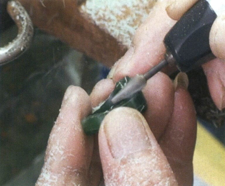
Figure 2-13 Rough finishing processing
(3) Fine Finishing
Fine finishing is based on rough finishing and further processing to make the entire wax sample more refined and aesthetically pleasing. First, a compass is used to take the dimensions of each part on the wax sample template and draw some auxiliary lines. Based on these auxiliary lines, remove the excess wax with a finishing bur, then use a steel bur to smooth out the rough marks left from the previous process. Use large and small spatulas to level off any corners or protruding parts on the wax sample, and refine it with a scalpel. Finally, large and small files smooth the overall wax sample.
(4) Removing Bottom Weight
The purpose of removing bottom weight is to reduce the weight of the workpiece. Install the ball bur and wheel bur on the electric hanging flexible shaft grinder, and use the ball bur to remove excess wax material at the bottom of the pattern head or the inner circle of the ring shank (Figure 2-14). Generally, the reserved bottom thickness for pave setting is 1.1 mm; for light gold and flush setting, it is 0.7 mm; for bezel setting and channel setting, it is 1.6 mm. Then, use a dental bur, drill bur, surgical knife, etc., to trim the wax sample’s bottom frame. During the bottom weight removing, it is important to frequently measure the dimensions at the light gold position, pave setting position, channel setting position, etc., using internal calipers to prevent deviations.
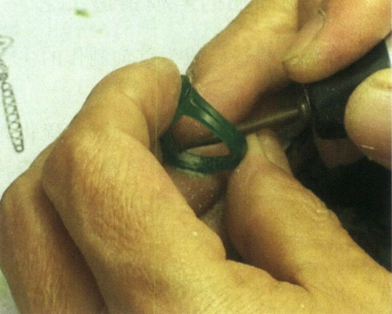
Figure 2-14 Removing the bottom weight
(5) Make the Stone Setting Position
According to the size of the stone and the setting method, open the stone position, use appropriate diamond drills for channel setting and bezel setting, drill holes at the designated stone position, and then use steel burs, small files, scalpels, etc. for adjustments; steel burs can also be used to directly open the stone position.
(6) Repair
Repair involves adjusting certain details to ensure that the repaired workpiece better meets the order requirements. During the repair, attention should be paid to adjusting and coordinating the relationship between wax weight and size according to the order’s requirements for product weight and dimensions.
(7) Polishing
Wipe the surface of the wax plate with nylon cloth to make it smooth and fine.
(8) Replicating Silver Model
After the hand-carved wax model is completed, it must be cast into a silver model to replicate the rubber mold. The surface of the cast silver model is then refined (Figure 2-15) to ensure a good surface finish, avoiding any defects on the silver model from being replicated onto the casting. The silver model’s shape, dimensions, and weight are checked to meet the order requirements. Additionally, some processes that the hand-carved wax model cannot complete are supplemented, such as planting prongs, creating buckles and buttons, dangling earrings, etc.
(9) Welding Sprues
The sprue is designed to leave a channel for the flow of molten metal during the casting process. In jewelry casting, because there is no set risers on the workpiece to make up for the contraction, the sprue has become a channel for the liquid metal filling but also needs to bear the liquid metal solidification contraction within the makeup for the contraction of the task, the correct setting of the sprue is to ensure that the casting quality of the basic conditions of the casting of many of the defects of the casting of the molten mold directly or indirectly by the setting of the sprue caused by the irrationality of the defects, such as insufficient filling, loosening, porosity, and other common defects.
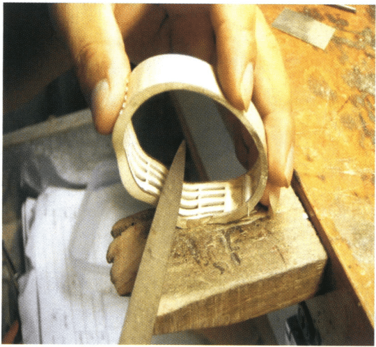
Figure 2-15 Finishing the silver model
1.2 Rubber Mold Making
(1) Fyllning och pressning av rågummi
Use an oil-based pen to draw the parting line along the edge of the model shape as the parting position for cutting the rubber mold. The parting line position is determined based on the principle of facilitating mold removal. Prepare the rubber plate and rubber particles according to the dimensions of the silver model, place the silver model in the appropriate position on the rubber plate, and fill the gaps, recesses, and stone-setting positions on the master model using methods such as plugging, wrapping, patching, and filling, ensuring there are no gaps between the silicone rubber plate and the master plate (Figure 2-16). Then, the remaining rubber plate is applied; to ensure the longevity of the rubber mold, it is usually pressed with more than four layers of silicone film. After being pressed into the mold frame, the rubber mold’s thickness is slightly higher than the plane of the frame by about 2 mm. During the operation, the silicone rubber plate must be kept clean, and direct contact with the surface of the silicone rubber plate should be avoided; instead, the protective rubber plate on the surface should be torn off after the silicone film is adhered.

Figure 2-16 filling rubber
(2) Vulcanization
First, preheat the vulcanizer, then place the molding frame with the pre-pressed silicone sheet inside and tighten the handle to press the heating plate against the molding frame. Carefully check if the heating plate is pressed tightly (Figure 2-17). The commonly used rubber has a vulcanization temperature range from 143~173℃, and the optimal temperature depends on the type of rubber. Before heating, press for a few minutes, then gradually increase the pressure. Choose the vulcanization time based on the model’s thickness; for example, 30 minutes for 12 mm thick, 45 minutes for 18 mm, and 75 minutes for 36 mm. Once the vulcanization time is up, quickly remove the rubber mold, and after it cools naturally to room temperature, you can proceed with the mold opening operation.
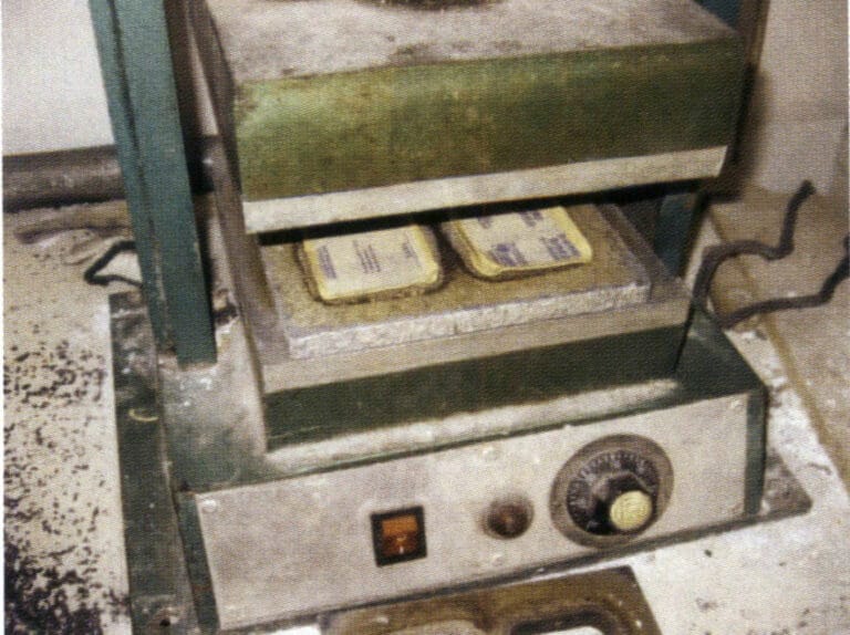
Figure 2-17 Sulfurization
(3) Opening the Rubber Mold
Opening the rubber mold involves cutting the pressed rubber mold to take out the original model (Figure 2-18) and dividing the rubber mold into several parts according to the complexity of the shape of the sample so that the wax mold can be smoothly removed after the wax injection. The opening of the rubber mold usually employs a four-foot positioning method.
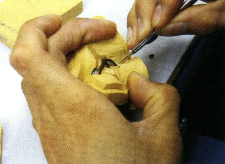
Figure 2-18 Opening mold
1.3 Wax Mold Making
Due to the fine nature of jewelry, when making wax molds, it is necessary to use the pressure of a wax injection machine to inject the wax liquid into the cavity of the rubber model. Many wax injection machines exist, including ordinary air-pressure wax injection machines, vacuum wax injection machines, and digital automatic wax injection machines. Place the wax material in the wax tank. The wax material must be kept clean, and the wax tank and nozzle’s temperature must be adjusted to the required temperature.
Before applying the wax, open the silicone mold and check its integrity and cleanliness. Spray release agent in the mold’s smaller, more complex areas (or sprinkle a small amount of talcum powder) to facilitate the removal of the wax mold.
Start the vacuum pump during wax injection and check if the wax temperature is between0~75℃. Adjust the injection time and air pressure according to the complexity of the wax parts in the mold, then evenly clamp the mold to perform the wax injection operation (Figure 2-19). The wax piece can be removed from the mold after cooling for about 1 minute. Care should be taken when removing the mold to avoid breaking or deforming the wax piece.
After removing the wax mold, carefully inspect it. If there are defects such as flash, clamping marks, unclear flower heads, or overlapping flower heads, they need to be trimmed with a surgical blade; for sand holes and broken claws, they can be repaired with a wax welder; small holes that are blocked can be penetrated with a welding needle; for deformation of the wax mold, it can be corrected in hot water at 40~50℃. Finally, cotton soaked in alcohol removes the wax shavings from the mold.
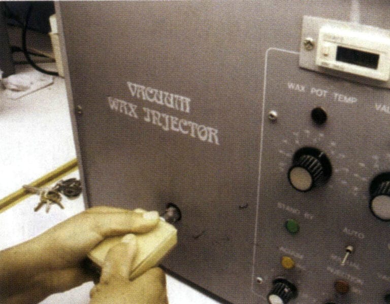
Figure 2-19 wax injection
1.4 Plating Wax Model Tree

Figure 2-20 Planting Wax Model Tree
1.5 Production of Gypsum Molds
(1) Investment – Mixing powder and Grouting
In the mold-making process, some typical machinery and equipment will be used, including simple powder mixers, vacuum extractors, automatic vacuum powder mixers, etc. The typical gypsum casting powder mixing and grouting process is shown in Figure 2-21.
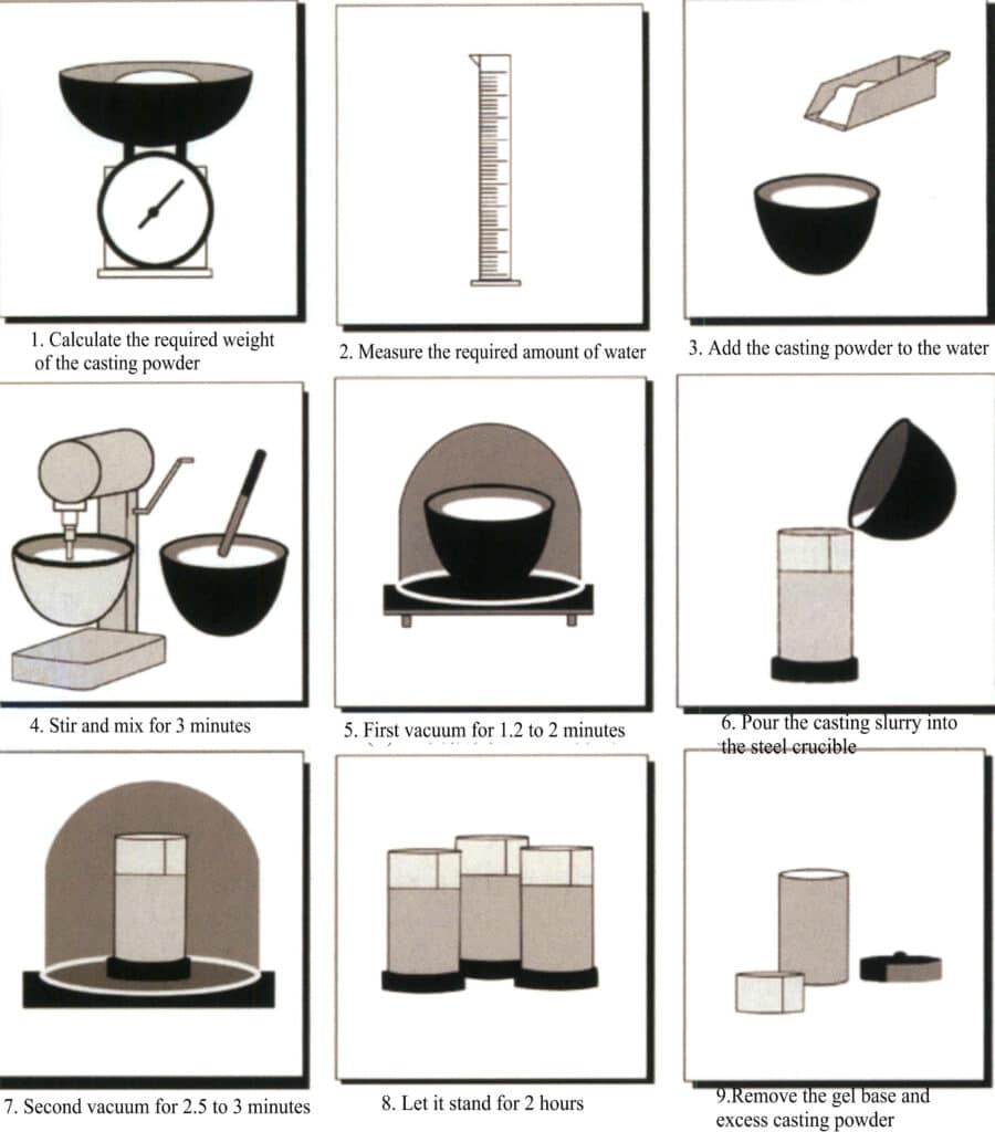
Figure 2-21 Schematic diagram of the gypsum casting powder mixing and grouting process
Due to the static electricity generated on the wax model tree, which easily attracts dust, it can be immersed in a surfactant or diluted detergent before grouting, washed with distilled water, and dried. During the powder mixing and grouting process, attention should be paid to appropriately controlling the setting time of the gypsum slurry. If it sets too quickly, the gas cannot be expelled in time; if it sets too slowly, the powder can easily settle in the slurry, resulting in a local change in the solid-liquid ratio, causing different roughness on the top and bottom of the jewelry.
After the casting mold is completed and the vacuum operation is performed, it should be allowed to stand for 1.5~2 hours to fully solidify and harden the gypsum mold. Then, remove the rubber base, the wrapping material around the steel flask, and the splattered slurry, and make marks on the side and surface of the casting mold.
(2) Wax Removal from the Mold
After the slurry solidifies, there are two different methods to remove the wax: steam dewaxing or drying dewaxing in a burnout furnace.
Steam dewaxing can remove wax more effectively and benefit the environment. Note that the boiling of water should not be too vigorous, and the time for steam dewaxing should be controlled; otherwise, splashed water may enter the mold and damage the surface of the mold. Additionally, in wax-setting casting, using steam dewaxing may dilute the boric acid protectant in the casting powder, leading to issues such as cloudy or discolored gemstones.
Burnout dewaxing is a method that directly uses a burnout urnace to heat the mold, allowing the wax material to melt and flow out of the mold. Due to the low boiling point of the wax material, when using this method, if the wax liquid boils violently, it can damage the surface of the mold, or if the wax liquid is not discharged smoothly, it can seep into the surface layer of the mold, both of which will deteriorate the surface quality of the casting. Therefore, it is important to control the heating temperature and speed during the dewaxing stage and to set up a corresponding insulation platform.
(3) Molding Burnout
The purpose of burnout is to eliminate the moisture from the gypsum mold and the residual wax, achieving the desired high-temperature strength and mold’s air permeability and meet the mold temperature requirements during pouring. The burnout system and equipment largely influence the final performance of the gypsum mold.
The gypsum burnout furnaces used in the jewelry industry generally adopt resistance furnaces, and some use oil-fired furnaces. Regardless of the type of furnace, the temperature distribution inside the furnace must be as uniform as possible. The resistance burnout furnace is commonly used, which generally adopts three-sided heating, and some use four-sided heating. They usually come with temperature control devices and can achieve segmented temperature control. Still, the temperature distribution inside the furnace is not uniform enough, and it is also difficult to adjust the atmosphere inside the furnace during burnout. In recent years, some advanced burnout technologies have continuously emerged, focusing on achieving uniform temperature distribution inside the furnace, eliminating wax residues, and automating control furnace. For example, a type of furnace uses a rotating bed method, with heating on all four sides, providing uniform and stable heat. The gypsum mold can be evenly heated, making it particularly suitable for the requirements of wax-set casting processes.
When roasting the mold, a suitable roasting system must be established, and a heat preservation platform should be set up during several sensitive stages. The mold is burn out at the highest temperature for 3~4 hours. After all residual carbon is burned off, the mold temperature needs to be lowered to a certain temperature to prevent defects such as shrinkage and porosity in the casting due to excessive mold temperature; however, since jewelry pieces are generally quite delicate and difficult to form, cold mold pouring is not used to ensure complete filling. Otherwise, the surface of the casting is prone to roughness and unclear contours. Generally, depending on the structure of the workpiece and the amount of casting, the mold temperature during pouring is between 520~650℃.
1.6 Melting and Pouring
(1) Alloy Pretreatment
In the casting production of jewelry, the effect of jewelry castings is closely related to the condition of the jewelry alloy. When pure metals and intermediate alloys are directly mixed and poured, it is easy to produce problems such as uneven composition, severe loss, and defects like holes. Therefore, it is generally necessary to pre-treat the jewelry alloy by melting and pouring various pure metals and alloy materials into beads or casting them into ingots and then proportioning them according to the required weight. The method of prefabricated beads is usually preferred, where the molten metal flows out from the crucible and instantly cools and splits into droplets when dripped into cooling water, solidifying solid metal particles (Figures 2-22 to 2-24). The round and appropriately sized alloy particles are beneficial for uniform composition during the melting process, temperature control, and reducing defects such as holes, sand holes, and hard spots, which are also closely related to the control of metal loss.
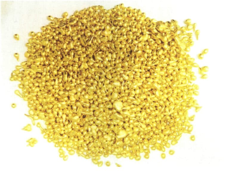
Figure 2-22 Brass particles
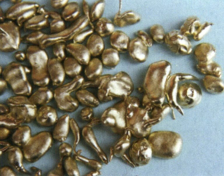
Figure 2-23 Cupronickel Granules
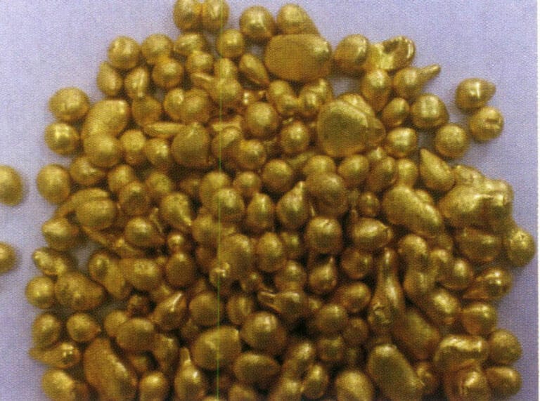
Figure 2-24 Bronze particles
(2) Alloy Smelting
The common melting methods for jewelry alloys are divided into two main categories: torch melting and induction melting.
① Torch smelting. Torch smelting to cast jewelry is a traditional production method using simple tools and equipment. First, the metal is melted using flames and then manually cast using simple pouring equipment. The combustion gases used in torch smelting include gas and oxygen, natural gas and oxygen, etc. Generally, oxygen-acetylene is not used because its temperature is too high, leading to significant metal loss and difficulty in control.
The smelting of torches generally uses clay crucibles. Before smelting, carefully check the quality of the crucible; the inner wall should have a smooth and dense glazed layer with no residual slag. Prepare the flux for slag formation, usually using anhydrous borax. First, preheat the crucible, then add copper particles, adjusting the flame intensity and nature to suitable levels. When the copper material is close to melting, sprinkle a small amount of borax on the liquid surface and gently stir the molten metal evenly with a glass rod (Figure 2-25). When the temperature reaches the required pouring temperature, the mold can be taken out for pouring.
During the smelting process, control the temperature and flame atmosphere; otherwise, serious oxidation will occur, leading to metal loss and slag contamination of the molten metal, especially in brass alloys, which are prone to significant zinc oxidation loss. The smelting temperature is generally controlled between 980~1020℃ to reduce metal loss and avoid prolonged.
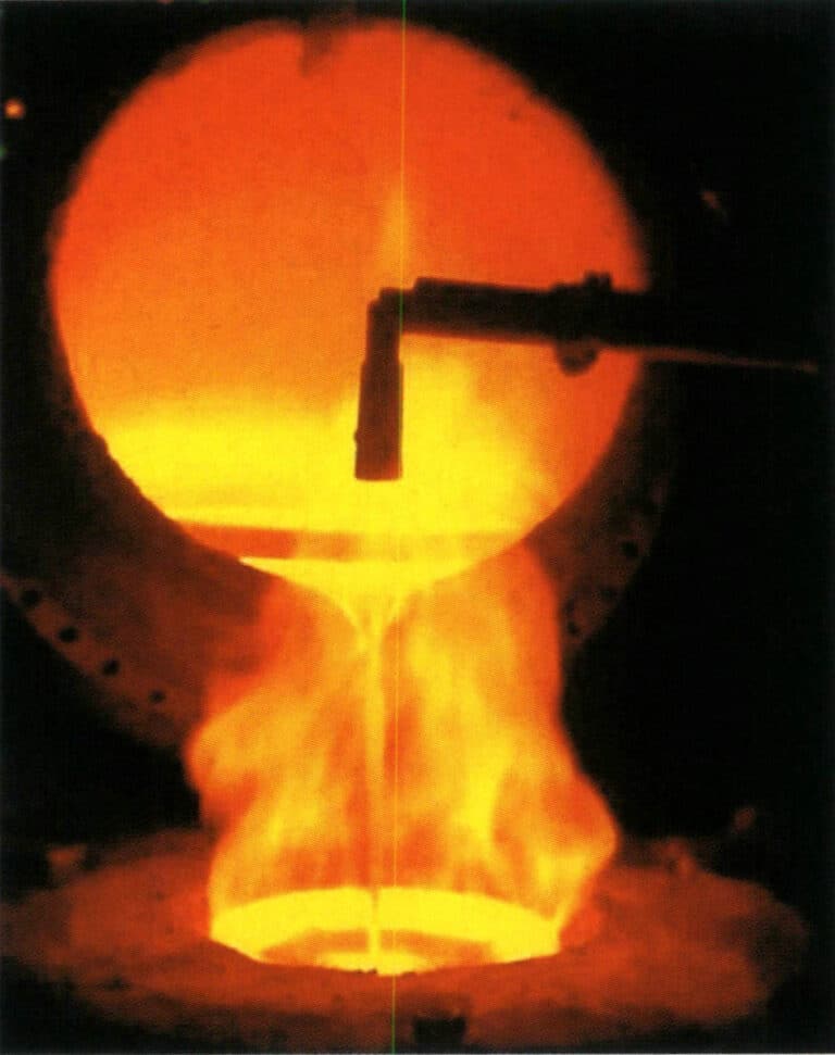
Figure 2-25 Torch smelting of copper alloys
② Induction melting. In the production of copper jewelry, the induction melting method is widely used to melt copper alloys (Figure 2-26). The control of the atmosphere during melting significantly impacts the quality of the molten metal. Generally, several methods exist, such as vacuum melting, inert gas protection melting, and reducing flame protection melting. Vacuum melting is beneficial for metallurgical quality; however, it is not suitable for copper alloys, especially brass alloys with high zinc content, because the vacuum exacerbates the volatilization of zinc, leading to severe metal loss, significant composition fluctuations, and the melting fumes can easily damage the vacuum system. Therefore, inert gases such as argon and nitrogen or reducing flames are generally used to isolate and protect the molten metal surface to achieve excellent metallurgical quality when induction melting copper alloys.
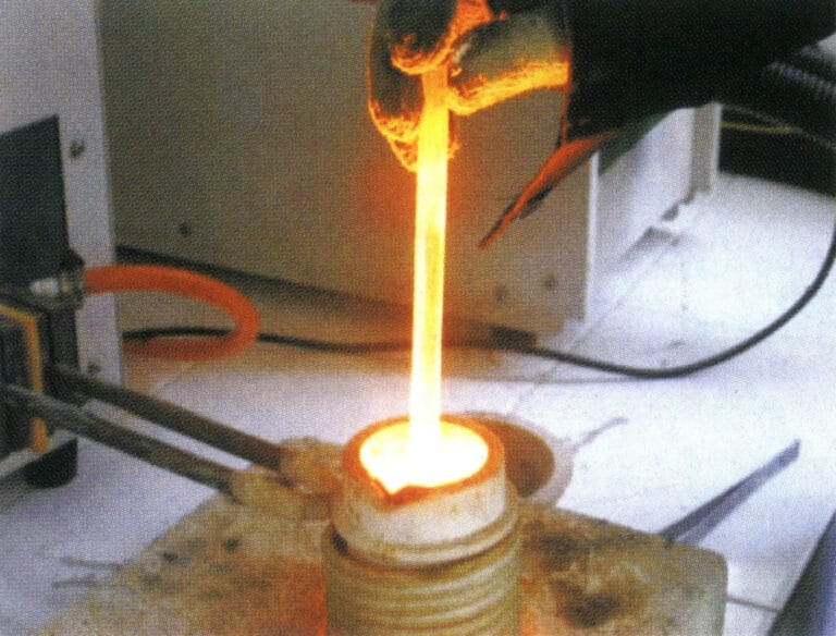
Figure 2-26 Induction Melting of Copper Alloys
(3) Pouring
Because jewelry pieces are relatively delicate, solidification occurs quickly during the casting process, resulting in a loss of fluidity. Therefore, conventional gravity casting struggles to ensure proper shaping, and it is necessary to introduce some external force to promote the rapid filling of the mold cavity with molten metal, achieving castings with complete shapes and clear contours. Based on the method of using external force, it can be divided into two main categories: centrifugal casting and static casting; based on the degree of automation in the casting process, it can be divided into manual casting machines and pressure casting machines.
① Manual pouring. Manual pouring is generally carried out with torch or induction melting. After the metal liquid is smelted and refined, the temperature is adjusted to the pouring temperature range. Then, the mold is removed from the burnout furnace to prepare for pouring. Depending on the type of equipment used, manual pouring mainly includes centrifugal casting and vacuum suction casting.
Figure 2-27 is a simple mechanical transmission centrifugal machine in some small jewelry processing factories. It does not come with an induction heating device, uses gas-oxygen to melt metal, or uses an induction furnace to smelt metal and pour it into a crucible. The gypsum mold is placed flat in the rotating arm’s mold base, and the rotating arm is started. Under the action of centrifugal force, the molten metal enters the mold cavity, completing the pouring process. Many factors affect quality during the operation, making it suitable for pouring small jewelry items, such as links, ear studs, etc.
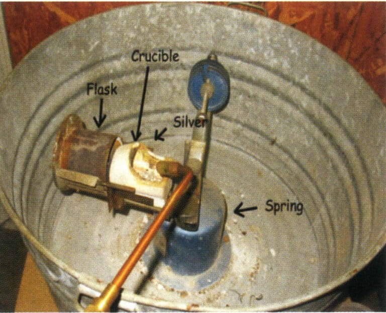
Figure 2-27 Simple Centrifugal Casting Machine Manual Pouring
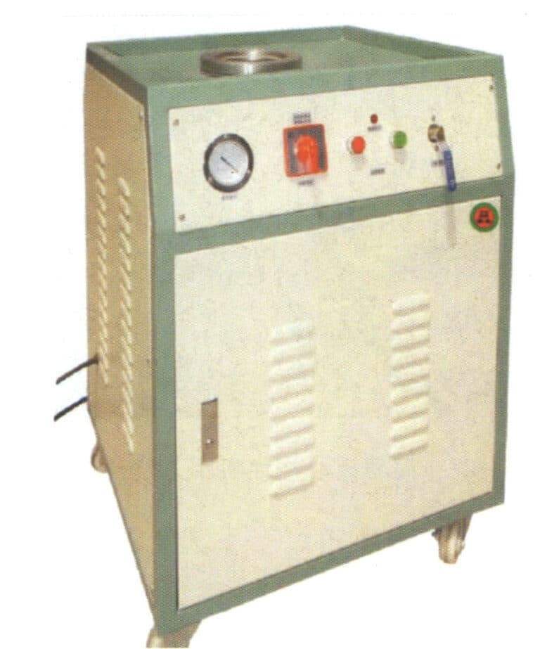
Figure 2-28 Manual pouring with the suction machine
② Automatic pouring of casting machines. With the increasing quality requirements for jewelry products and the technological advancements in the jewelry industry, automatic casting machines have become very important equipment in the lost-wax casting of jewelry, serving as an important foundation for ensuring product quality. Based on the type of external force used, the commonly used jewelry casting machines are divided into two categories: centrifugal and static casting.
In response to the shortcomings of traditional simple centrifugal casting machines, modern centrifugal casting machines integrate induction heating and centrifugal casting, achieving significant advancements in drive technology and programming, improving programming capabilities and process automation control. Figure 2-29 shows a typical melting and casting chamber of a jewelry centrifugal casting machine, which can be used for casting copper alloy jewelry.
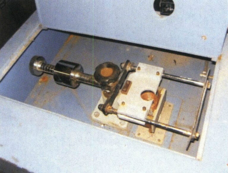
Figure 2-29 Automatic pouring of centrifugal induction casting machine
The most advanced and widely used static casting machine is the automatic vacuum pressure casting machine (Figure 2-30). There are many models of this type of machine, and the casting machines produced by different companies each have their own characteristics. Still, they generally consist of induction heating, vacuum systems, control systems, etc. In terms of structure, they are generally upright, with the upper part being induction chamber, the lower part being a vacuum casting chamber. The bottom of the crucible has a hole, which is sealed with a refractory plunger rod during melting. When pouring, the plunger rod is lifted, and the molten metal is poured into the mold cavity. Generally, a thermocouple is installed inside the plunger rod, which can accurately reflect the temperature of the molten metal. Automatic vacuum casting machines typically melt and cast metals under vacuum or inert gas atmospheres, reducing the possibility of metal oxidation and gas absorption. They are widely controlled by computer programming, have a high degree of automation, and produce stable quality castings with reduced porosity defects, making them highly regarded by many manufacturers. This equipment is used in small quantities for casting copper jewelry with low zinc content, while for copper alloys with high zinc content, it is generally used less frequently to avoid damaging the vacuum system.
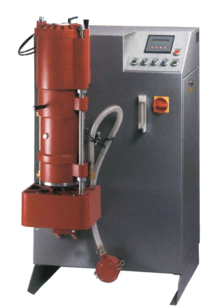
Figure 2-30 Automatic pouring of vacuum pressure casting machine
1.7 Casting Cleaning
After the casting is poured, it is left for about 15 minutes; then, the mold is quenched in water to perform the explosive gypsum operation. The residual heat of the casting powder mold encounters the cooling water, causing the water to vaporize instantly, resulting in an explosive powder phenomenon that separates the cast workpiece from the casting powder mold.
Use a high-pressure water jet to wash away the residual casting powder on the surface of the workpiece. The washed workpiece is generally black. Soak the washed casting in a water solution of hydrofluoric acid, sulfuric acid, or hydrochloric acid. The acid soaking thoroughly removes the residual casting powder from various parts of the casting and the oxidized inclusions on the surface of the casting. When soaking copper jewelry in hydrofluoric acid solution, the concentration is about 5%, and the soaking time is about 20 minutes.
After removing the casting powder, the workpiece is still in a tree-like shape and needs to be cut at its sprue, classified, and sorted by type to prepare for the next process. First, weigh the tree-like blank after removing the casting powder, calculate the loss during the casting process, and then perform the sprue cutting operation.
1.8 Post-processing of Castings
To achieve various surface effects for jewelry and to inlay different types of gemstones, post-processing of the castings is crucial. Typically, it involves several main processes: mechanical polishing, finishing, setting, and surface treatment (such as polishing, electroplating, coloring, etc.). Below is a brief introduction to these main processes.
(1) Finishing
The finishing process is the integration, fitting, welding, and rough surface processing of jewelry blanks, restoring them to their original model. The finishing procedure is an important step in the jewelry-making process. The quality of jewelry will be directly affected if the finishing process is not well executed. According to jewelry products’ categories and structural characteristics, they can be divided into several typical types, such as rings, earrings, chains, and bracelets. Their finishing processes are not the same, but they generally go through the following procedures.
① Shaping. Restore the workpiece to its original model and standard dimensions.
② File the sprue. First, use a coarse file to smooth the sprue and surface, then use a smooth file to repair various parts of the workpiece to make it smooth (Figure 2-31).
③ Assemble welding or weld repair sand holes. Weld the fittings in the appropriate position on the workpiece, serving as decoration or fixing the assembled workpiece (Figure 2-32). When sand holes appear on the workpiece, use solder for repair.
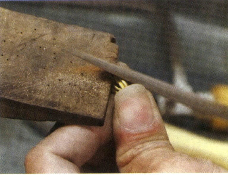
Figure 2-31 Water sprue
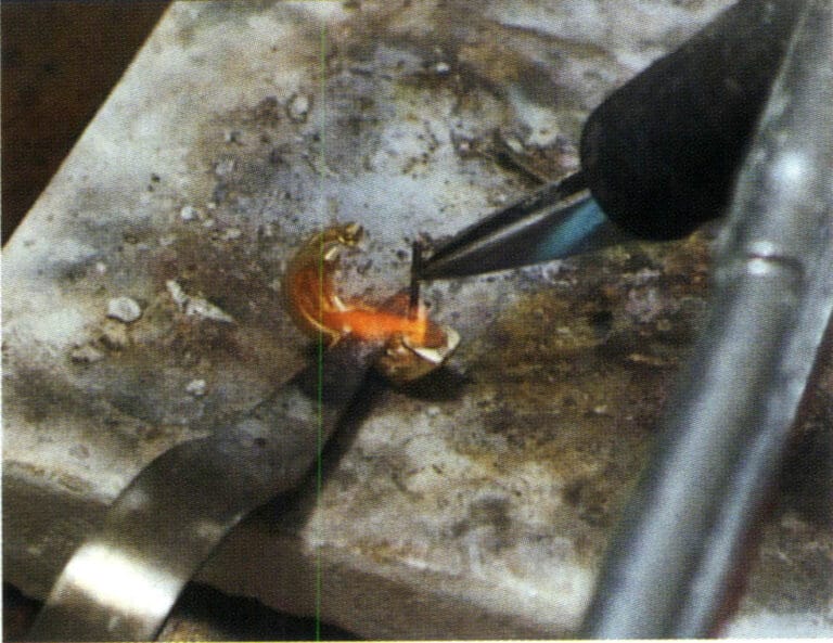
Figure 2-32 Assembly Welding
④ Boiling in alum solution. After welding, the workpiece will form a black-gray substance on the surface, which can be removed after boiling in alum water to clean the impurities on the surface of the workpiece (Figure 2-33).
⑤ Filing the surface. Use a sliding file to grind the inner circle, outer circle, and side of the ring to make the surface smooth and free of burrs, with a smooth shape.
⑥ Sandpaper polishing. Sandpaper removes the workpiece’s file marks, making the workpiece’s surface smooth (Figure 2-34).
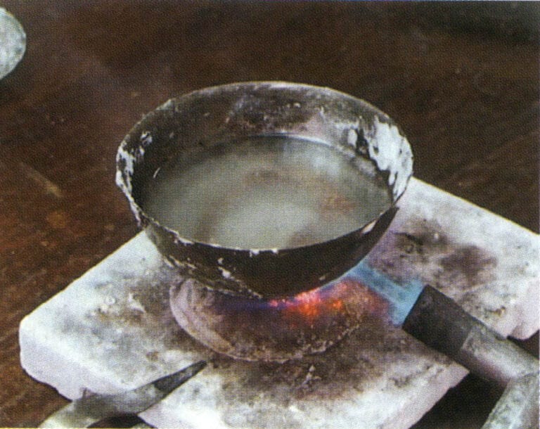
Figure 2-33 Boiling in alum water
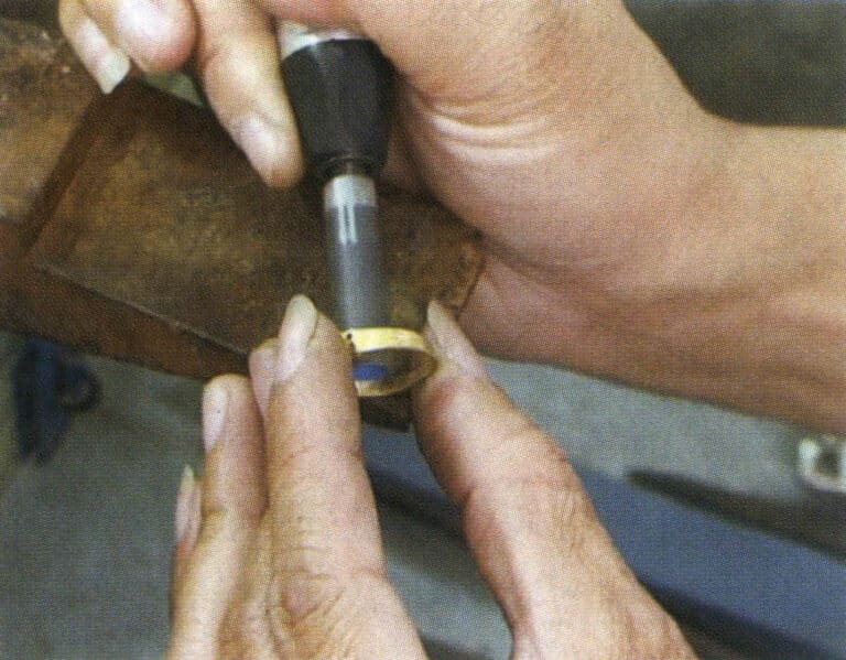
Figure 2-34 Sandpaper polishing
(2) Insättningsstenar
Setting craftsmanship is a technical method that combines gemstones of different colors, shapes, and textures through extensive setting, filing, carving, chiseling, and welding to create various shapes and styles, giving them a high appreciation value as crafts and decorative items.
Common inlay methods mainly include inverted pave setting, prong setting, flush setting, Italy setting, pavé setting, channel setting, and invisible setting. The overall process of stone setting is divided into three main steps: preparation before setting, setting operation, and surface finishing after setting.
① Preparation work before setting stones. Mainly divided into two steps: selecting stones and applying fire lacquer.
Selecting stone: It involves checking the quality, quantity, and weight of various specifications of gemstones according to the order to see if they meet the requirements. Then, they are screened and classified, and the gemstones are allocated according to the customer’s order quantity for the setting department to arrange production.
Applying fire lacquer: It is to fix the workpiece on the fire lacquer handle, making it easier for the operator to hold and manipulate during the stone inlaying process. Mostly used for earrings, pendants, and other inlaid pieces; other inlay methods depend on the specific processing requirements of the goods.
② Setting operation. The setting operation is generally divided into five basic steps: measuring stone position, polishing stone position, placing the stone, fixing the stone, and repair. The main inlay methods include prong setting, pave setting, channel setting, flush setting, bezel setting, invisible setting, etc. Taking prong setting as an example, its operation steps are shown in Figure 2-35.
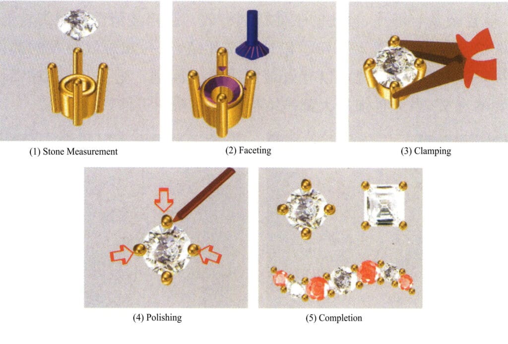
Figure 2-35 Schematic diagram of prong setting operation process
③ Surface finishing. It mainly includes three steps: washing the fire lacquer, edge finishing, and edge scraping.
Washing the fire lacquer involves using a torch to bake the wax on the workpiece after the stone is inlaid, then removing the workpiece and soaking it in turpentine to clean the wax.
Edge finishing: It is the process of using tools such as files, machine burs, and sandpaper to smooth the rough surface of the workpiece, restoring the surface of the workpiece after stone setting to a smooth and soft state.
Edge trimming: It is the process of leveling the burrs on the inner side of the workpiece’s gold edge after bezel setting, channel setting, and flush setting, making the inner edge lines smooth and the surface bright.
(3) Surface Treatment
There are many surface treatment methods for copper alloy jewelry, and electroplating is one of the most commonly used surface treatment methods. It generally includes three main stages: pretreatment, electroplating, and post-treatment.
① Preprocessing. Polishing is a key process to achieve the best appearance effect for jewelry. Commonly used equipment includes ordinary polishing machines and disc polishing machines, with ordinary polishing machines being of two types: simple and recycling. When the polishing wheel rotates at high speed, high temperatures are generated between the jewelry, the polishing wheel, and the molten buffing compound, which enhances the plasticity of the metal, improves the fine unevenness of the surface, and increases the brightness of the jewelry (Figure 2-36). The effect of polishing mainly depends on the characteristics of the surface to be processed, that is, the degree of polishing and leveling of the workpiece surface, as well as the type and characteristics of the polishing materials used during the polishing process. Polished jewelry should achieve a smooth, flawless finish, symmetrical shapes, smooth lines, uniform thickness, rounded edges, and corners, and be free of issues such as broken prongs or loose stones.
The surface of jewelry that has been polished almost inevitably adheres to wax or oil stains, and it needs to undergo a degreasing treatment before electroplating. Common degreasing methods include ultrasonic degreasing and electrochemical degreasing. Ultrasonic degreasing can further enhance the speed and effectiveness of solvent and chemical degreasing, has minimal corrosion on the substrate, and offers high degreasing and purification efficiency, making it particularly effective for complex workpieces with fine holes and blind holes. Ultrasonic cleaning machines have become an indispensable piece of equipment in jewelry making (Figure 2-37). In the past, cleaning dead corners, blind holes, and hard-to-reach areas has been a difficult problem, but ultrasonic cleaning can effectively solve this issue. This is particularly significant for jewelry, as most pieces are complex and finely structured workpieces.
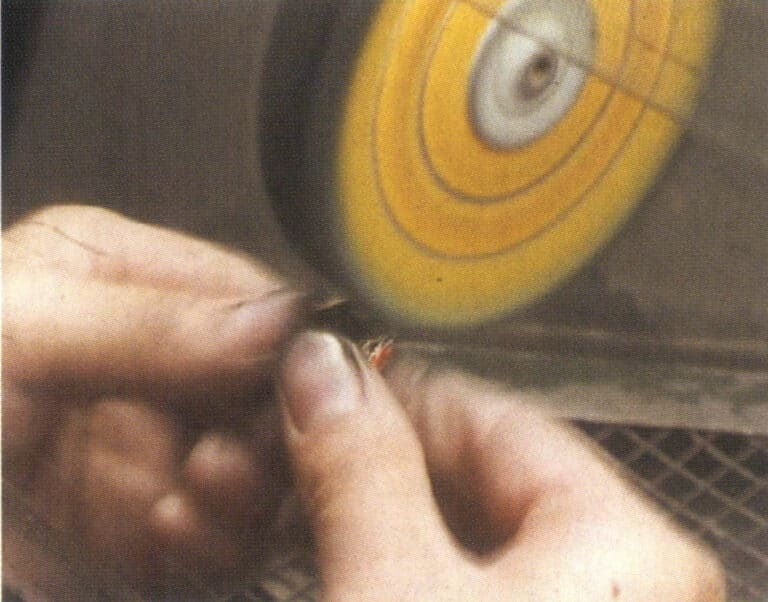
Figure 2-36 Cloth Wheel Polishing
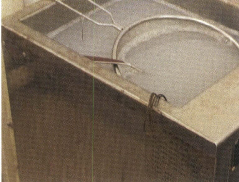
Figure 2-37 Ultrasonic Grease Removal
Electrochemical degreasing involves hanging the jewelry on the cathode or anode of an alkaline electrolyte (Figure 2-38). During electrolysis, the bubbles escaping from the surface of the jewelry have a strong tearing effect on the grease film on the surface, and the agitation caused by the rising bubbles continuously carries away the oil, further enhancing the degreasing effect. The speed of electrochemical degreasing exceeds that of chemical degreasing, resulting in good effectiveness.
Jewelry must be cleaned and weakly etched before entering the electroplating tank. The purpose of cleaning is to remove the adhering liquid on the surface of the jewelry, promote the deposition of metal ions, and avoid contaminating the electroplating solution. Copper jewelry is generally cleaned before plating using a multi-stage countercurrent cleaning production line, as shown in Figure 2-39. The main purpose of etching is to neutralize any alkaline solution that may remain on the surface of the workpiece, dissolve the oxide film on the surface of the workpiece, and activate the surface to ensure a strong bond between the plating layer and the base metal. The concentration of the etching solution is generally quite dilute, 1%~5%, and will not damage the surface finish of the material, with the time usually only a few seconds to 1 minute.
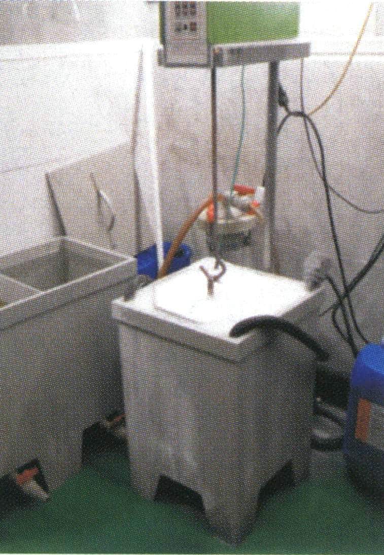
Figure 2-38 Electric De-oiling
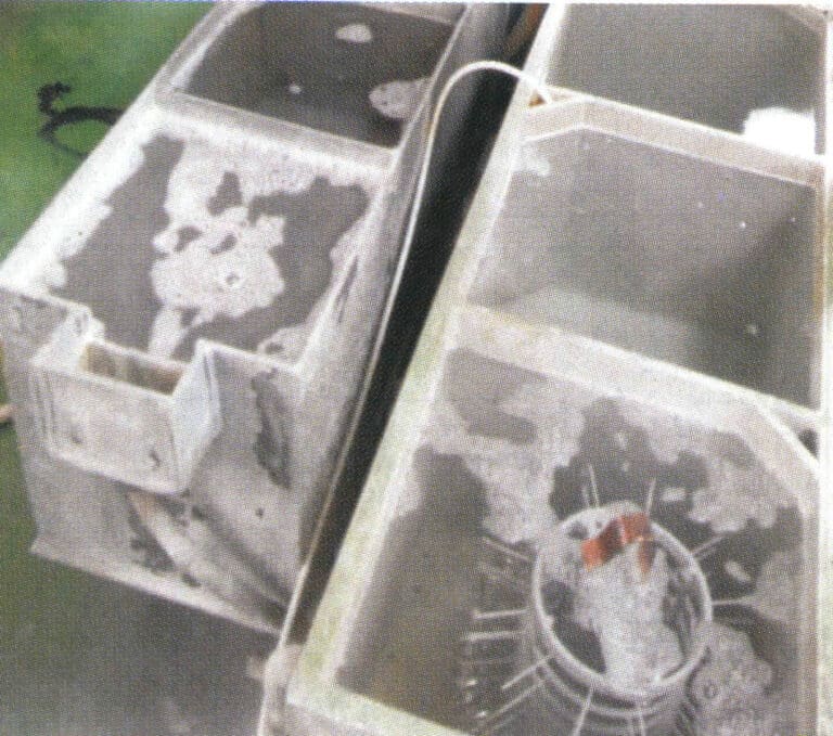
Figure 2-39 Pre-plating cleaning
② Electroplating operation. The surface electroplating of copper jewelry generally includes several methods, such as silver plating, gold plating, and rhodium plating. When gold plating or rhodium plating, a layer of nickel is usually pre-plated on the surface of the jewelry. During production, it is necessary to regularly monitor the electroplating solution in the plating tank and various key material indicators to prevent mismatches in indicators, which could lead to product quality issues.
③ Post-plating treatment. The workpiece, after electroplating, is first dipped in a plating solution recovery cup, rinsed with water, soaked in hot pure water, then rinsed with a steam washing machine, and finally dried with a hot air gun.
2. The Stamping Process of Copper jewelry
The stamping process is widely used in producing copper jewelry, especially white ones, most of which use the stamping process. The process is very similar to that of stainless steel stamped jewelry; for details, see the introduction in other articles.
3. The Electroforming Process of Copper jewelry
3.1 Introduction to Electroforming Technology
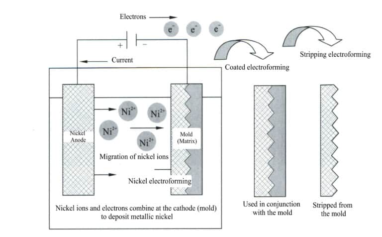
Figure 2-40 Electroforming Schematic
Use the original mold made in the desired shape as the cathode and the electroforming material as the anode, and place them together in a metal salt solution that is the same as the anode material, applying direct current. Under the action of electrolysis, the metal electroforming layer is gradually deposited on the surface of the original mold and reaches the desired thickness, it is removed from the solution, and the electroforming layer is separated from the original mold, thus obtaining a metal replica corresponding to the shape of the original mold.
Compared to the lost-wax casting process, electroforming can produce larger workpieces with very thin walls, making it particularly suitable for crafting decorative items. The main disadvantage of electroforming is its low efficiency, with the thickness of the electroformed metal layer generally being 0.02~0.05 mm per hour. By using a high-concentration electroforming solution appropriately, increasing the solution temperature, and enhancing stirring, the current density can be improved, reducing the electroforming time and thereby increasing the efficiency of electroforming.
3.2 Electroforming Process of Copper jewelry
The typical electroforming process for copper jewelry includes sculpting the mold, replicating the mold, wax mold injecting, wax mold finishing, applying silver plate, electroforming, finishing, wax removing , and polishing.
(1) Wax Mold Making
Making wax molds involves designing wax material, sculpting the mold, replicating the mold, wax molds injecting, and wax molds finishing. When making large workpieces, clay carving templates are also used, which are copied into silicone and wax molds.
① Sculpting the wax mold. Carved into a wax template using high relief, low relief, openwork, and line carving techniques. First, initial rough carving is performed, which is done according to the design intent and process conditions, using carving tools to shape the wax material into a certain form to determine its basic shape; after the initial rough process, fine carving and detailed finishing are carried out to address various shortcomings from the previous steps and to make the surface of the wax mold smooth and polished.
② Replicating molds. Copy the qualified carved wax model into a rubber mold to achieve the purpose of mass production.
For small copper jewelry, first, fix the wax model on a glass surface, surround it with sandpaper, leaving a certain distance between the model and the sandpaper tube, then vacuum the uniformly mixed silicone and inject it into the sandpaper tube (Figure 2-41), then vacuumed, and glue is injected according to the actual situation. After filling it with silicone, please place it in the vacuum machine to vacuum, and put the last vacuumed sandpaper tube in a suitable and stable position to let it dry naturally.
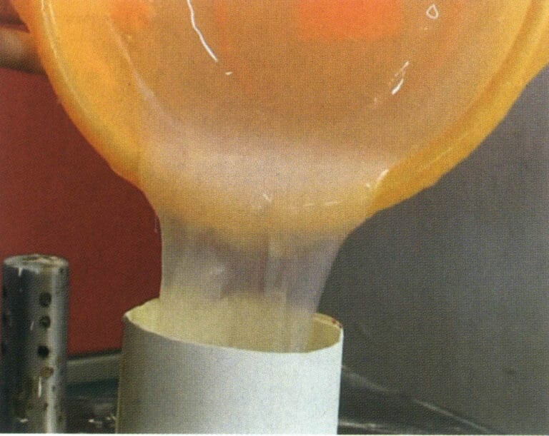
Figure 2-41 Replicating rubber mold
For large copper ornaments, the method of first applying glue on the template and then using plaster for replication is generally adopted. Fix the model on a disc, and use a brush to apply the prepared silicone on the template. After the first layer is qualified, repeat the brushing two more times until the thickness reaches 3~5 mm. Use the oil clay to fill the larger concave hole. Then, use the right amount of water to mix a good plaster paste, with a flat shovel and hand (wearing rubber gloves) scraping and wiping plaster mud on the mold plate, a thickness of about 20 ~ 30mm. Scraping and wiping, depending on the complexity of the shape of the model, is broken down into several parts of the production, divided into two pieces, complex divided into 3 ~ 4 or several pieces, to facilitate the removal of the rubber mold and the model. After the work, the entire mold is placed to dry naturally, with a rubber hammer to knock the decomposed plaster layer.
③ Mold cutting. Use a scalpel to cut the silicone layer at the appropriate position and remove the model. When cutting the mold, choose areas that are easy to repair so that the poured wax mold is easy to finish (scrape) on the plate. Avoid cutting through the facial features of sculptures of people or animals. After cutting the mold, check the quality of the silicone mold to see if there are any bubbles and whether the silicone molds fit together tightly. For large decorative items, close the cut silicone mold, use plaster to decompose the mold to hold the silicone mold together, fix it, and then use glue lines and glue tape to secure it tightly.
④ Wax mold injecting. Use the gas from an air compressor to blow away impurities inside the rubber mold, then place the mold in an electric oven to preheat for about 5 minutes, allowing the mold’s temperature to reach 60~65℃ and remove moisture. Remove the mold from the oven, close it, and ensure the joints are completely sealed, securing them with rubber bands. Use an iron spoon to scoop the wax from the electric heating tank and pour it into the rubber mold (Figure 2-42), then place it in a vacuum-vibrating machine to vacuum for 1~2 minutes, remove the wax supplement, and vacuum again for 1~2 minutes. After completing the injecting, supplementing, and vacuuming, place the rubber mold on the workbench to cool naturally. Once the pouring opening has solidified, stand the mold in a plastic basin filled with cold water to accelerate the wax solidification. The solidification time depends on the volume of wax, generally over 30 minutes and sometimes up to 1 day. Once the wax model inside the rubber mold has completely solidified, loosen the rubber bands and tape and open the rubber mold to remove the wax figure.
⑤ Wax mold finishing. Use a wax scraper or surgical knife to remove the flash, wax marks, sprues, etc., from the wax mold (Figure 2-43), and make the entire surface of the wax mold beautiful and smooth. Use an electric soldering iron to dot wax to fill small holes and other defects on the wax mold or connect several wax parts. Wipe the surface of the wax mold with gasoline to make it clean and smooth.
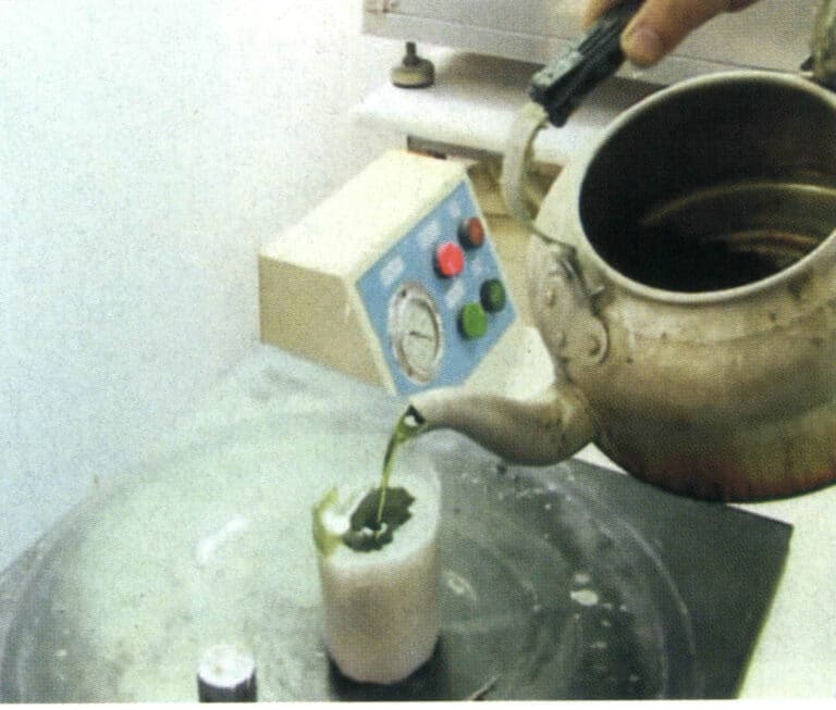
Figure 2-42 Wax mold injecting
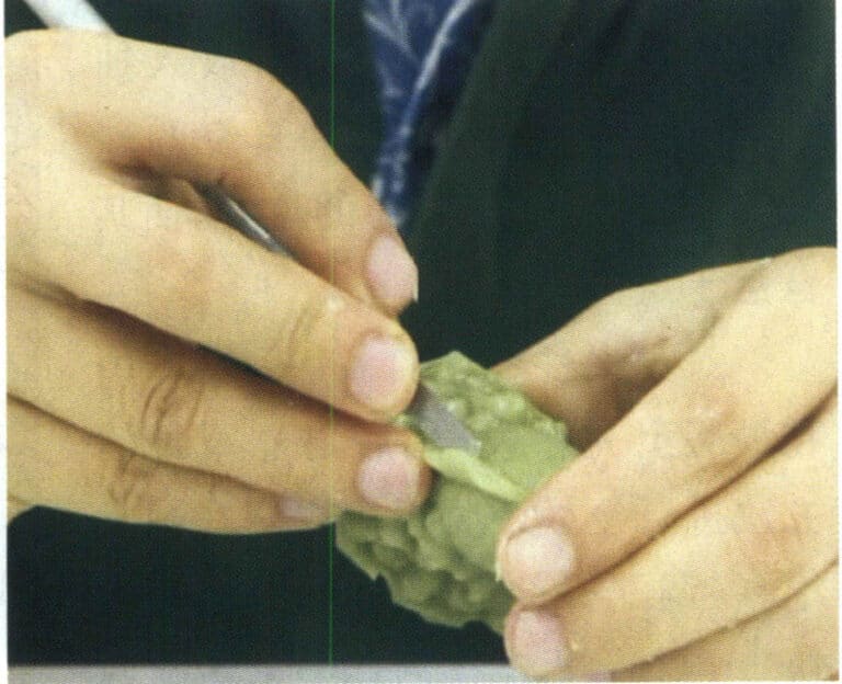
Figure 2-43 Wax mold finishing
(2) Electroforming
Hollow electroforming is the process of hollow electroforming jewelry pieces based on a wax mold, using silver plate coating and electroforming technology. For larger pieces and those with special requirements, electroplating is also needed for the surface processing treatment.
① Insert hanging rods. Hanging rods must be inserted into the wax mold to facilitate the electroforming of the casting tank and achieve fixation and conductivity.
② Apply silver plate (conductive layer). Since the wax mold is not a conductive material, a uniform layer of silver plate must be applied to the surface of the wax mold. During the natural drying process of the silver plate, the acetone in the solvent evaporates, and a very thin conductive layer is formed on the surface of the wax mold, thus preparing for the electroforming process (Figure 2-44).
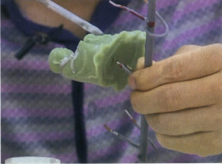
Figure 2-44 Silver Plate Coating
③ Open reserved holes. To remove wax and silver plate and ensure the purity of the metal in the ornament, it is necessary to leave reserved holes for post-processing. This avoids increasing metal loss and the likelihood of product scrap due to opening holes in the finished product. Opening reserved holes should follow two points: first, it should not affect aesthetics and should be placed in a relatively concealed position; second, the quantity and size should be appropriate. Therefore, it must be coordinated with various processes such as wax carving, engraving characters, inserting rods, and post-processing, and cannot be done independently.
④ Weighing. Place the wax mold with the iron hanging rod on the electronic scale to understand and control the weight of the casting.
⑤ Place the mold into tank for electroforming. The wax mold must be cleaned with pure water before placed into tank to remove dust from the surface; otherwise, the casting may develop perforations due to dust. Areas with more recesses in the wax mold should face the metal mesh of the casting cylinder, which ensures a faster-pouring speed in the recesses and a more uniform casting layer. Otherwise, the pouring speed in the recesses will be slow, resulting in a thin casting layer after demolding, which may lead to perforations during grinding and wax removal.
At the expected start time, take out the casting for weighing. If the weight meets the required range, it can be started and cleaned, and then the hanging rod from the casting can be registered and handed over to the next process operation.
(3) Surface Treatment
Copper electroformed parts generally require gold plating on the surface. For plush sand products, a thin layer of gold is usually plated immediately after copper electroforming. The gold plating process occurs after surface treatment of the copper electroformed parts for water and products. Typical surface treatment tasks include finishing, drilling, wax removal, polishing, and gold plating.
① Finishing. Perform preliminary treatment on the cast surface to remove burrs.
② Wax removal. Remove the wax inside the casting to make the casting a complete metal body, a hollow, multi-layered jewelry craft casting.
First, place the jewelry in the 150~300 ℃ electric oven for 20~30 minutes to burn out the wax from the jewelry. Remove it while hot and place it in the ultrasonic wax removal machine to eliminate any remaining wax. After removing the wax, remove the jewelry and pour the water inside, then place the casting in the ultrasonic cleaning machine for cleaning. Rinse the surface of the casting with tap water, use an air gun to blow away the water droplets inside and outside the casting, and let it air dry naturally on the workbench.
③ Baking in the oven. After cleaning the surface of the accessory, please place it in the oven of 750℃ for about 10~20 minutes to bake at degrees to remove moisture and impurities in the sand, preventing the appearance of red spots, eliminating internal stress, and changing the brittleness of the accessory.
④ Polishing. Polishing certain areas of the castings to make the product appear more striking, dazzling, and noble.
⑤ Gold plating. The main purpose is to enhance the surface protection of the workpiece and prevent discoloration of the workpiece surface. The workpiece is placed in a chemical degreaser and cleaned in an electro-degreasing tank to remove surface oil. After cleaning the water, the gold plating operation is performed.


