One time to know all things about Gemstone Crystallography
A comprehensive guidebook about Crystallography forms, types, classifications and differences
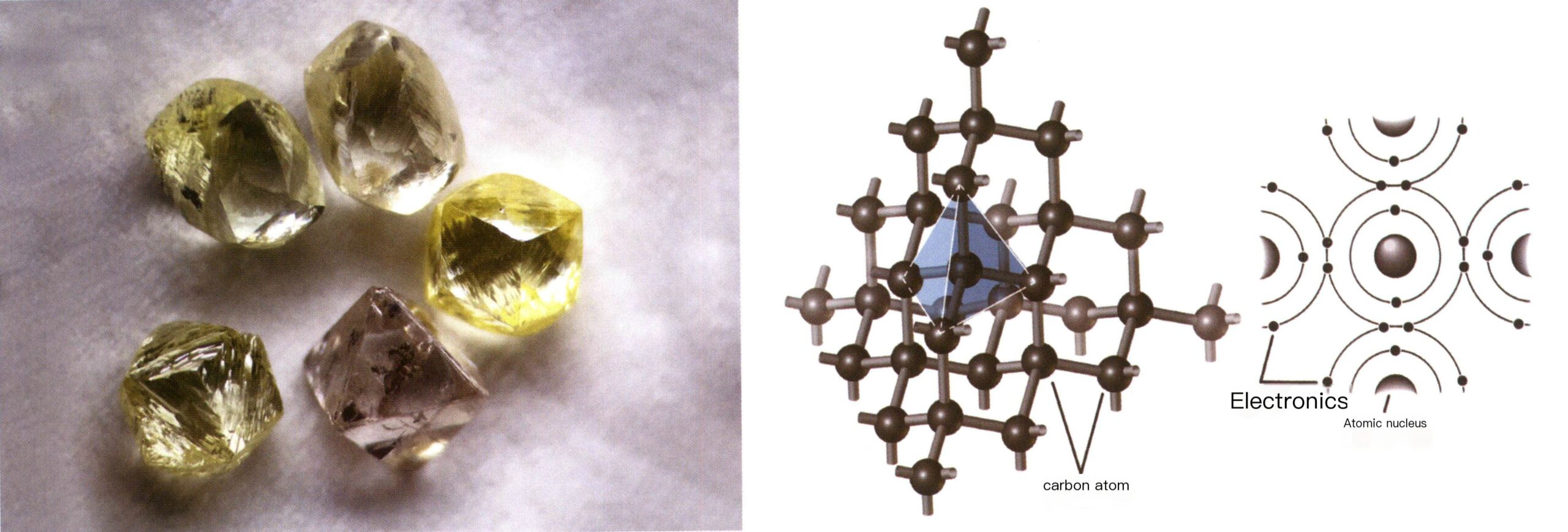
The Earth is composed of countless molecules and atoms. Modern scientific research has found that solid materials in nature are made up of different chemical elements. X-ray analysis results show that the atoms in the elements of certain solid materials are arranged neatly and regularly together. These materials are classified as crystalline or referred to as crystals, and their orderly Atomic lattice is called crystal structure (Figure 2-1-1).
Most gem materials that grow in nature and laboratories are crystalline. This chapter will discuss the concept of crystals, their classification, and the relationship between crystals and basic terminology in gemology.
Spis treści
Section ⅠThe Concept and Description of Crystals
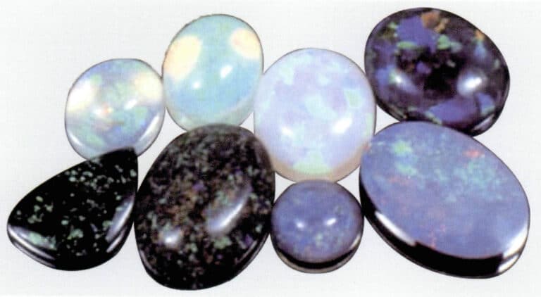
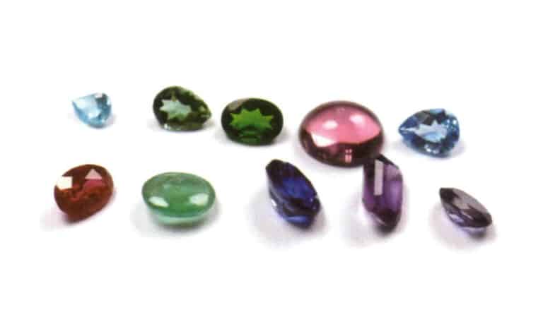
When we mention gems, we often think of their sparkling and translucent characteristics (Figure 2-1-2). From the perspective of geologists and gemologists, most beloved gems belong to a geometric form of solid—crystals. The essence of the beauty of crystals is, in fact, the beauty of geometry.
1. The concept of Crystals
Crystals are the most easily associated and most commonly found in nature. Crystals are found on all seven continents of the Earth, and when found in nature, they often take the form of geometric polyhedra (Figure 2-1-3). They are commonly referred to as crystals. Later, this term was extended to refer to naturally occurring solid substances with geometric polyhedral shapes, such as diamond and aquamarine crystals (Figure 2-1-4). Crystals can also describe solid materials with irregular, uneven, worn, broken, or artificially processed surfaces but with an atomic arrangement that still follows a regular pattern. Crystallographers believe all crystals possess six basic characteristics: self-limiting, uniformity, anisotropy, symmetry, stability, and fixed melting point.
① Self-limiting refers to the property of chemical elements to spontaneously form geometric polyhedral shapes. This property can explain why different elements have different crystal geometric shapes.
② Uniformity refers to the property that all crystal parts’ physical and chemical properties are the same. This property can help us distinguish and identify different mineral crystals.
③ Anisotropy refers to the property where the arrangement of elements varies in different directions, leading to slight differences in physical properties depending on the direction. This property can explain why diamonds with the highest hardness can be cut and polished.
④ Symmetry refers to the property where identical parts or properties in a crystal are repeated in a regular pattern. This property is extremely important and special for crystals and will be elaborated on in the second section of this chapter.
⑤ Stability refers to a crystal’s stability resulting from its minimum internal energy. If the internal energy of a crystal is high and uneven, it is prone to cracking on its own. This property can explain why ruby crystals synthesized by flamefusion technique always appear to be half rather than complete.
⑥ Fixed melting point refers to the property that a crystal has a fixed melting point.
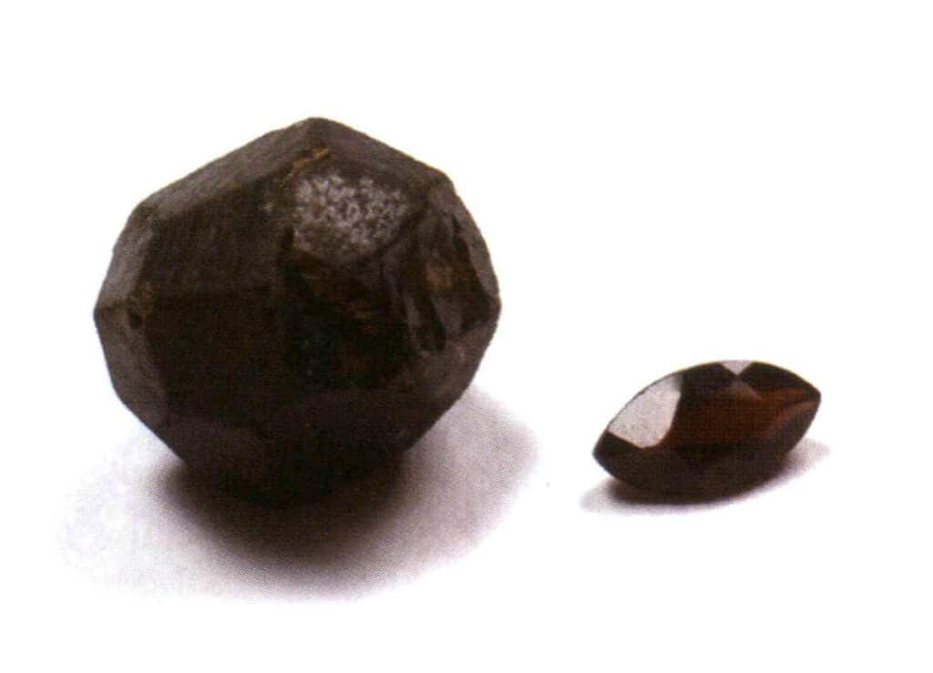
Figure 2-1-3 Garnet (left side is the crystal, right side is the polished garnet)

Rysunek 2-1-4 Kryształ akwamarynu
2. The Ideal Form of Crystals
The crystals discussed in crystallography are mainly ideal single crystals. An ideal single crystal is defined as one whose internal structure strictly follows the rules of spatial lattices and whose shape is a regular geometric combinate form. The forms of ideal single crystals are divided into two types: simple forms and combinate forms.
(1) Simple Form
A simple form refers to a combination of a group of crystal faces connected by symmetry elements, which can be understood as a geometric body composed of crystal faces of the same shape and size in an ideal state (Figure 2-1-5). There are 47 types of simple forms in crystals.
The key points for identifying simple forms are: all crystal faces in the crystal are of the same shape and size, and the crystal faces can be oriented differently.

(2) Combinate Form
The aggregation of simple form is called combinate form, composed of two or more different simple forms. Not all simple forms can be freely combined into combinate form; only simple forms with the same point group can aggregate (Figures 2-1-6 to 2-1-8).
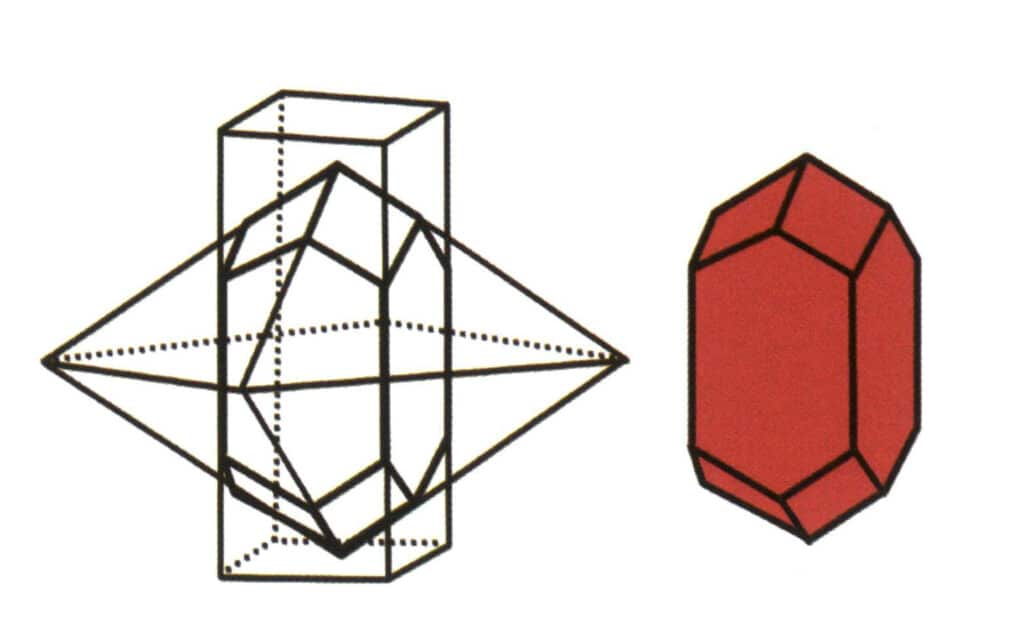
Figure 2-1-6 Combinate from of Tetragonal Prisms and Tetragonal Dipyramidal
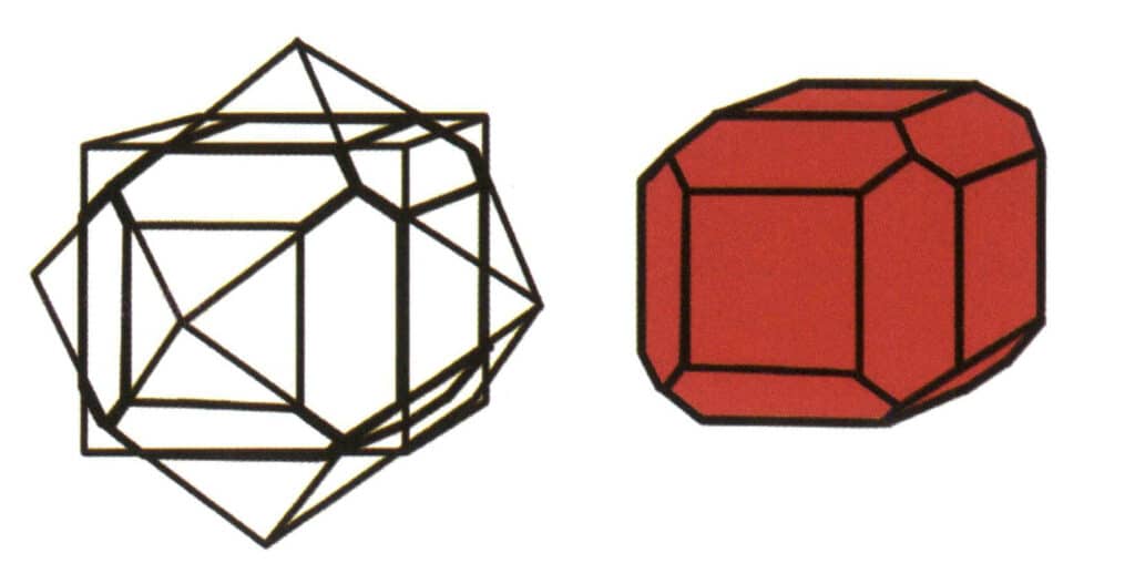
Figure 2-1-7 Combinate from of Cubes and Rhombic Dodecahedra
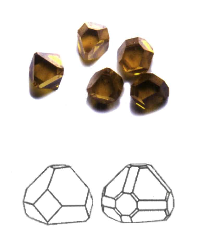
The key point of combinate form identification is the presence of two or more differently shaped crystal faces in the crystal.
When single crystals are found in nature, they always have a significant difference from the ideal morphology of single crystals (Figure 2-1-9), such as a single face not necessarily being of the same shape and size and the disappearance of crystal faces, which is described as distorted crystals.
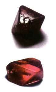
Distorted crystals can also be described as real crystals produced in nature, influenced by the growth environment. The multiple crystal faces that repeat at fixed angles in ideal crystals may not necessarily be the same shape and size. Still, for the same type of crystal, the crystal faces of the same monomorphic must have the same pattern and physical properties. The angles between corresponding crystal faces remain unchanged, reflecting the inherent symmetry of the crystal itself. The crystals found in reality are distorted to varying degrees.
Twinned crystals can also be described as actual crystals produced in nature, influenced by the growth environment. The multiple crystal faces that repeat at fixed angles in ideal crystals may not necessarily be the same shape and size. Still, for the same type of crystal, the faces of the same form must have the same patterns and physical properties. The angles between corresponding crystal faces remain unchanged, reflecting the inherent symmetry of the crystal itself. The crystals found in reality are all, to varying degrees, twinned.
3. The Crystallization Habits of Crystals
Crystals formed in nature can never achieve a perfect shape. If they grow in the gaps of rock layers, surrounded by rock, the crystal’s natural shape will be distorted. Even crystals cultivated in a laboratory will be deformed due to the influence of gravity. Only under the zero-gravity conditions of the International Space Station can scientists cultivate the perfect-shaped crystals they seek.
Although the shapes of crystals are imperfect, each type of mineral crystal tends to grow or cluster together in different ways or habits.
Each mineral tends to form under specific conditions, and its habits reflect the conditions of its formation. Some minerals, such as quartz, have complex and variable formation conditions. Thus, quartz also possesses multiple habits.
In general, crystal habits refer to the characteristics of a certain crystal tending to form a specific shape under certain external conditions. Sometimes, it refers to the common types of that crystal’s simple form.
Based on the degree of development of crystals in three-dimensional space, crystal habits are divided into three basic types.
(1) Uni-directional extension
Crystals extend in one direction, appearing in columnar, acicular, fibrous forms, etc. Minerals such as beryl, tourmaline, hornblende, and malachite often exhibit this habit (Figures 2-1-10 to Figure 2-1-11).
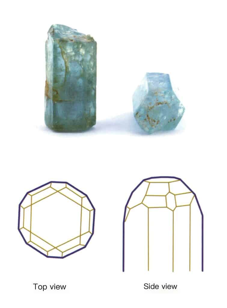
Figure 2-1-10 Columnar Aquamarine (top) and its Crystal Habit Diagram (bottom)
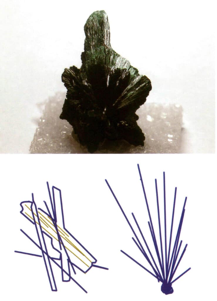
Figure 2-1-11 Fibrous Malachite (top) and its Crystal Habit Diagram (bottom)
(2) Bi-directional extension
Crystals extend in a plane, appearing in plate-like, sheet-like, scaly forms, etc., as minerals like wolframite, mica, plumbago, and tanzanite often exhibit this habit (Figure 2-1-12).
(3) Tri-directional isometric
Crystals develop uniformly in three directions, presenting isometric, granular forms, such as spinel, garnet, diamond, pyrite, and fluorite, often exhibiting this habit (Figures 2-1-13, 2-1-14).
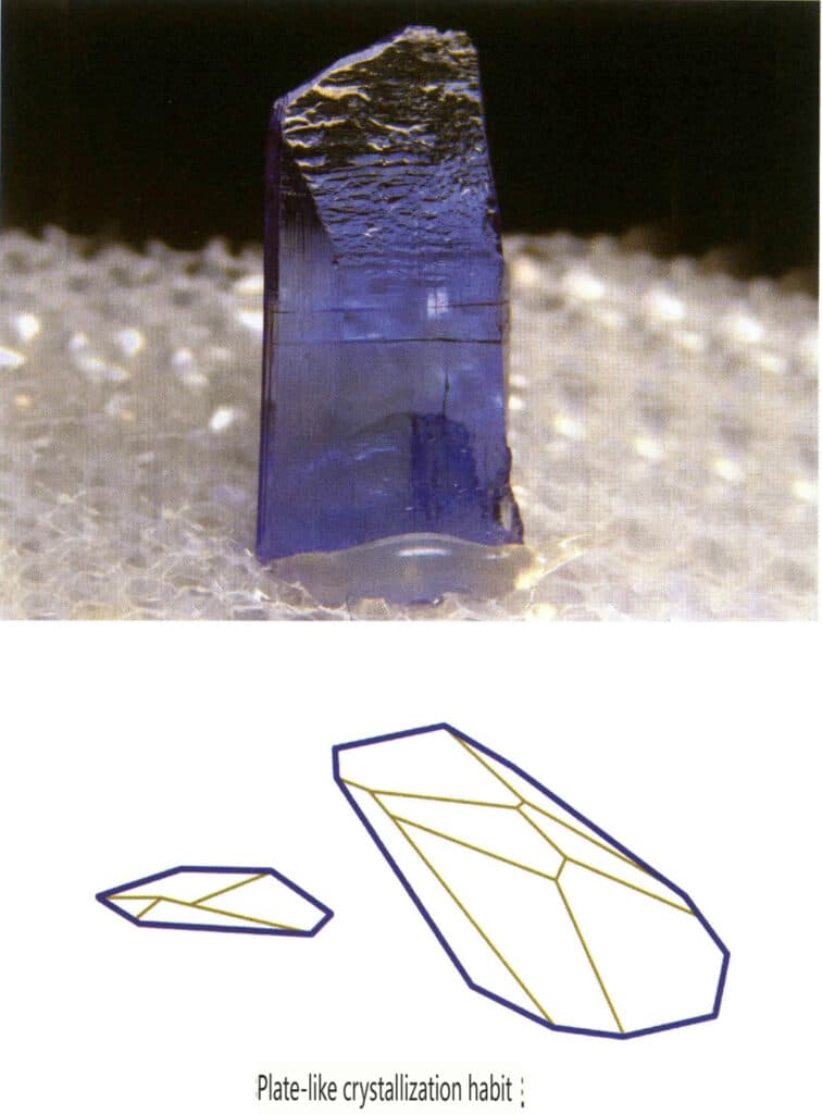
Figure 2-1-12 The plate-like crystal habit of tanzanite (top) and its crystal habit diagram (bottom)
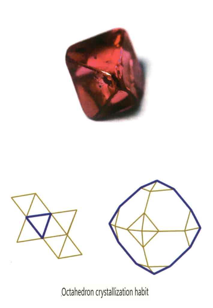
Figure 2-1-13 The octahedral crystal habit of the gemstone spinel (top) and its crystal habit diagram (bottom)
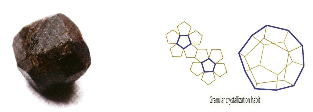
In addition, there are transitional types such as short columnar, plate columnar, strip-like, and thick plate forms.
The crystal’s chemical composition and structure mainly determine the crystal habit. It is also closely related to the external conditions during crystal formation (such as temperature, pressure, concentration, viscosity, and impurities), such as the differences in crystal shapes between diamonds and synthetic diamond crystals.
4. Regular aggregation of crystals
In nature, we can find individual crystals (Figure 2-1-15) and two or more single crystals growing together to form a whole. This phenomenon of multiple crystals growing together is called crystal aggregation. Crystal aggregation can be categorized into irregular and regular types. Irregular crystal aggregation can be understood as a collective, which Chapter Three will elaborate on. In regular crystal aggregation, there are four common types: parallel aggregation, bicrystals, overgrowth, and intergrowth (Figures 2-1-16 to 2-1-18). This section mainly discusses the type of regular aggregation known as bicrystals.
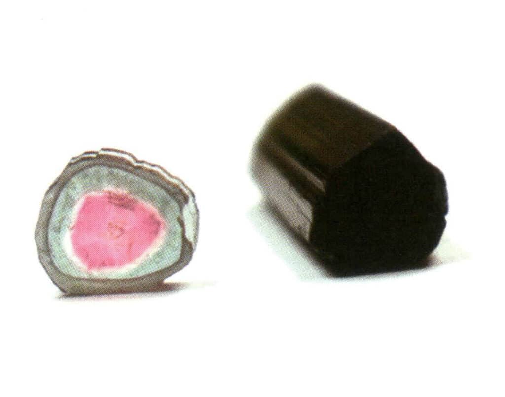
Figure 2-1-15 Monocrystal (Tourmaline)
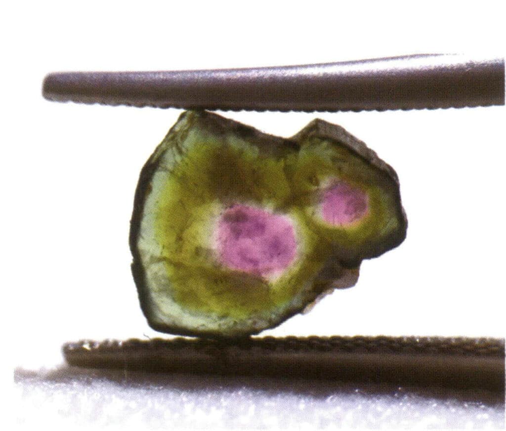
Figure 2-1-16 Parallel aggregation (When multiple crystals of the same type grow parallel in space, it is called parallel aggregation. At this time, the corresponding crystal faces and edges of the grown crystals are all parallel to each other.)
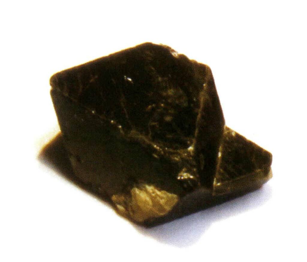
Figure 2-1-17 Twin crystal (Spinel)
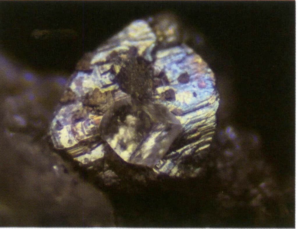
Figure 2-1-18 Overgrowth (a type of crystal grows on the surface of another crystal in a specific crystallographic direction, also known as epitaxial growth)
Bicrystals is the regular aggregation of two or more identical crystals according to certain symmetrical rules. (Twin axis, twin plane) The two adjacent individuals’ corresponding faces, edges, and angles are not completely parallel. Still, they can reflect each other through symmetrical operations such as rotation and rotation inversion, allowing the two individuals to coincide or align.
4.1 Key Points for Identifying Bicrystals
① Concave angles visible in twinned crystals (Figure 2-1-19).
② Stylolite: The micro-morphology and other characteristics of the crystal surfaces on both sides of the stylolite are discontinuous (Figure 2-1-20).
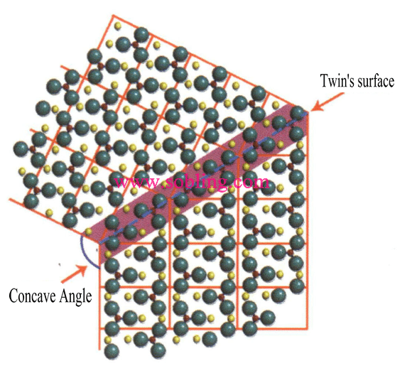
Figure 2 - 1-19 Twin's Concave Angle
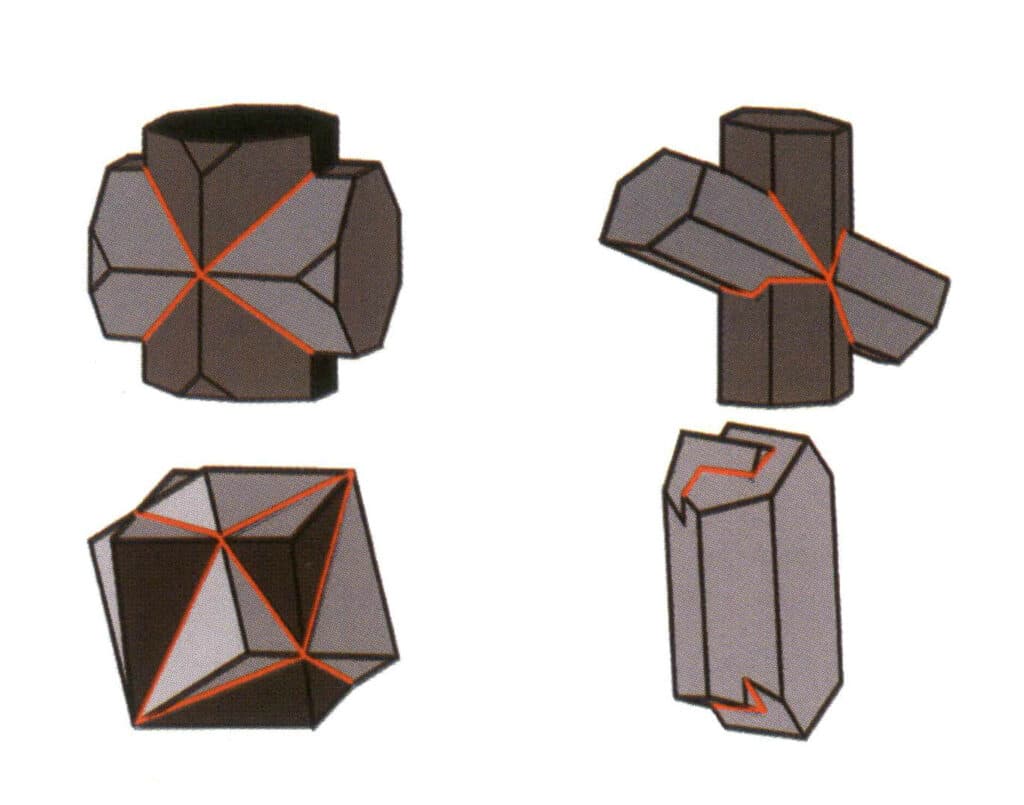
Figure 2-1-20 Stylolite (different colors in the figure represent different crystals; the red lines indicate the twin stylolite)
③ Twinning striation: Crystal faces or cleavage planes show fine twinning striations (Figure 2-1-21)
④ Etch figure: The appearance of the etch figure indicates the presence of twinning (Figure 2-1-22)
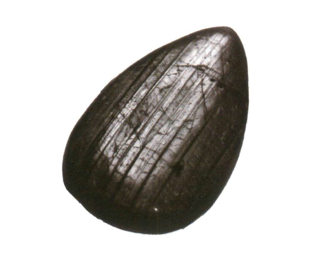
Figure 2-1-21 Schematic diagram of polysynthetic twins
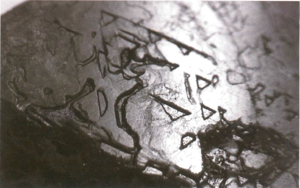
Figure 2-1-22 Surface of spinel with inverted triangular pits.
⑤ The appearance of pseudo-symmetry: the emergence of symmetry relations inconsistent with the inherent point group of the crystal single crystal (Figure 2-1-23 to Figure 2-1-24).
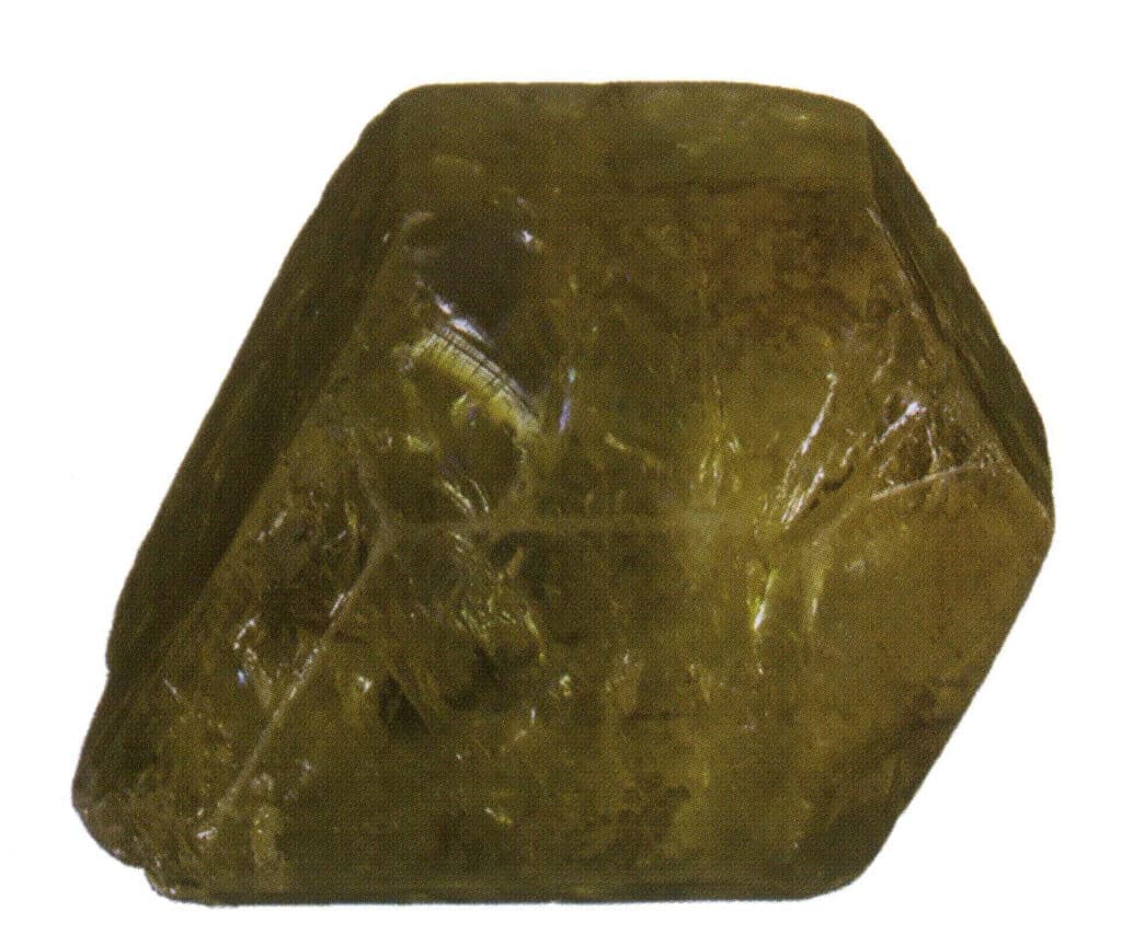
Figure 2-1-23 Single crystal of chrysoberyl
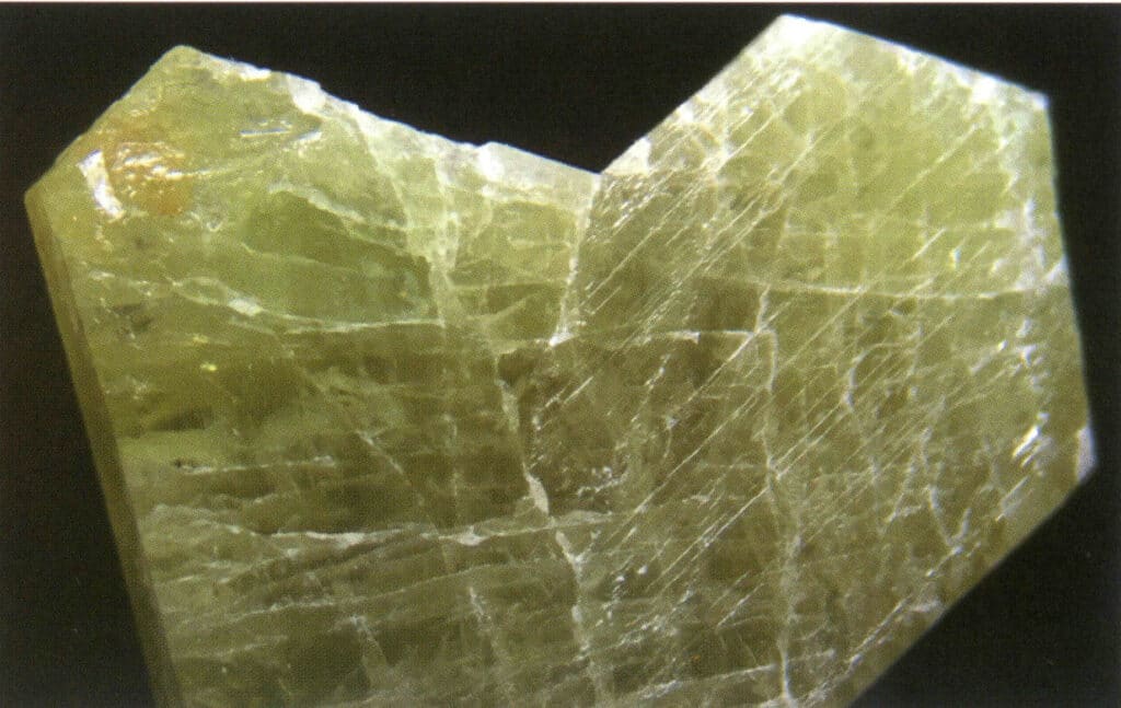
Figure 2-1-24 Knee-shaped twin of chrysoberyl
Twinning is divided into five types based on their stacking characteristics: contact twins (Figure 2-1-25 to Figure 2-1-26), polysynthetic twins (Figure 2-1-27), interpenetrating twins (Figure 2-1-28), triplet crystal (Figure 2-1-29), and complex twins, among which the first four types are common.
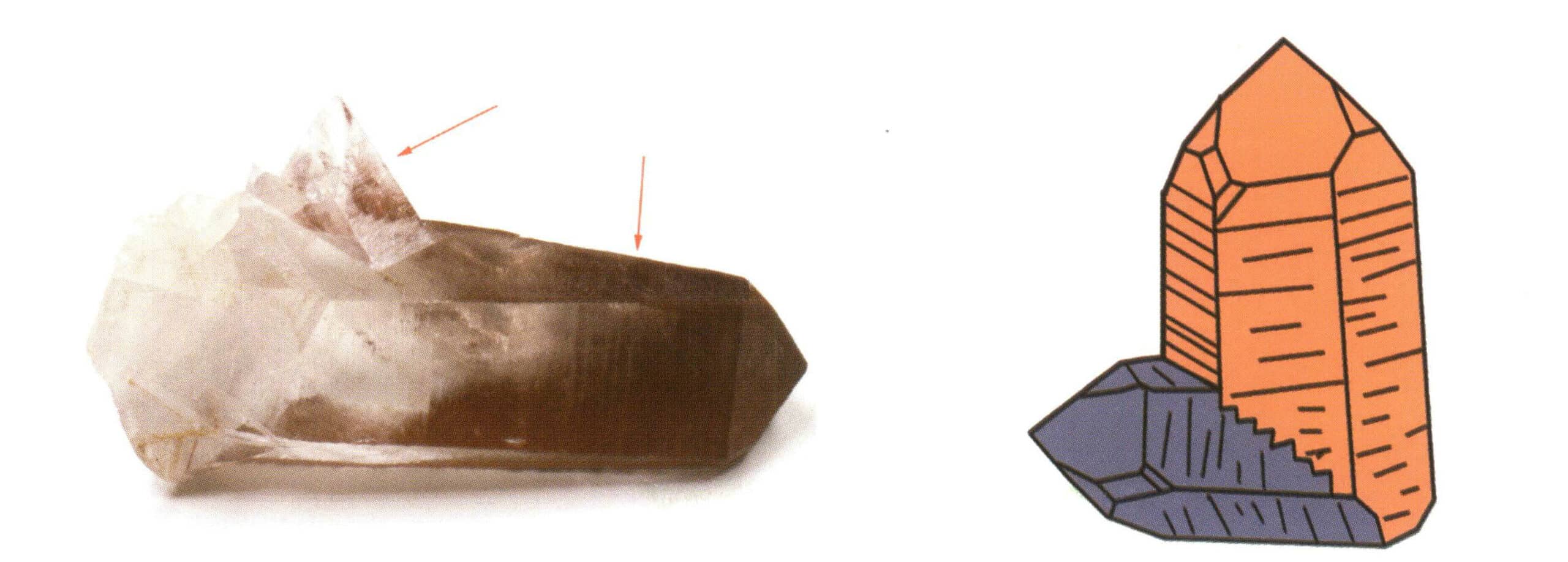
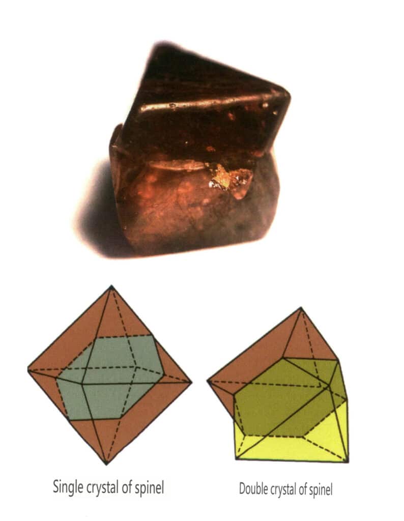
Figure 2-1-26 Contact twinning of spinel (top) and its schematic (bottom)
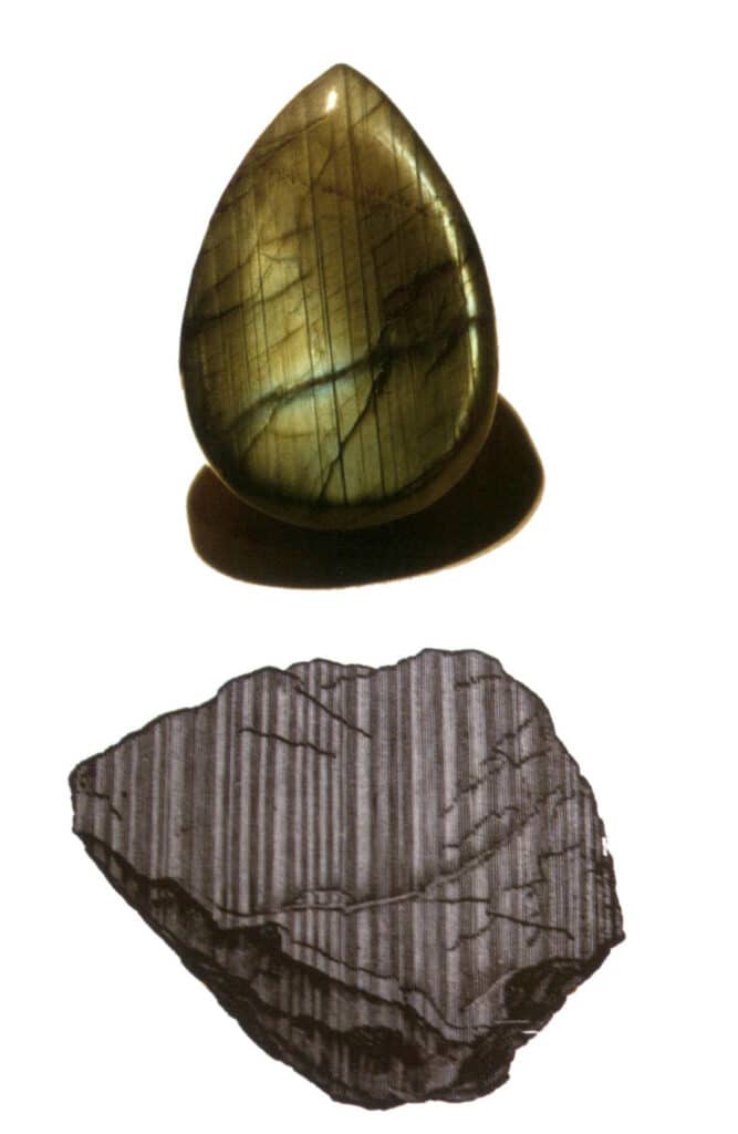
Figure 2-1-27 Polysynthetic twin of labradorite (top) and its schematic (bottom)
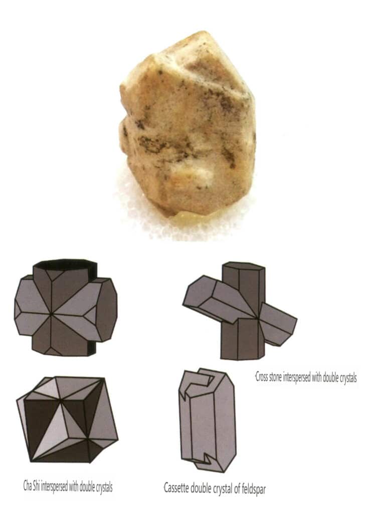
Figure 2-1-28 Feldspar Twin Crystals (top) and Schematic of Interpenetrating Twin Crystals of Other Types (bottom)
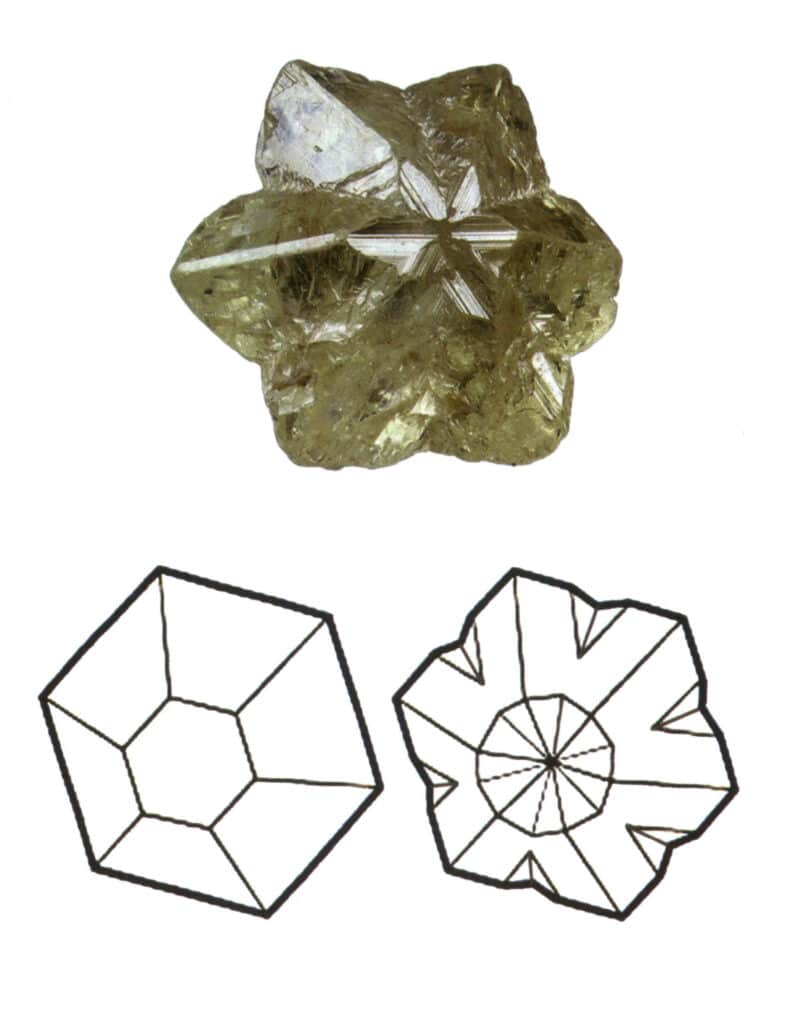
Figure 2-1-29 Trigonal twinning of chrysoberyl (top) and its schematic (bottom)
4.2 The formation of bicrystals
① Formed during the crystal growth, it can develop from twin crystalline germs or small crystals growing dependently according to the twin’s position.
② Formed during the heteromorphism transformation process, such as when α quartz transforms into β quartz, forming twins.
③ Formed by mechanical action, where a part of the crystal slides along a certain directional plane to form deformation twins, such as the twins of calcite.
5.Crystal Face Patterns
When crystals are discovered in nature, they often have incomplete shapes (Figure 2-1-30) and special surface patterns. Sometimes, they grow together in clusters (Figure 2-1-31), which often show significant differences from the standard geometric polyhedra we are familiar with, such as cubes and hexagonal prisms. This phenomenon is called the real form of crystals. The real form of crystals has a detailed classification in crystallography, such as distorted crystals, convex crystals, curved crystals, floating crystals, crystal face stripes, etch figures, twinning striations, etc.
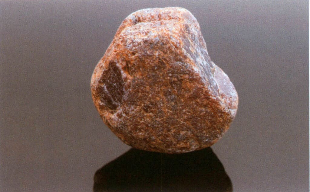
Figure 2-1-30 Ruby Crystal
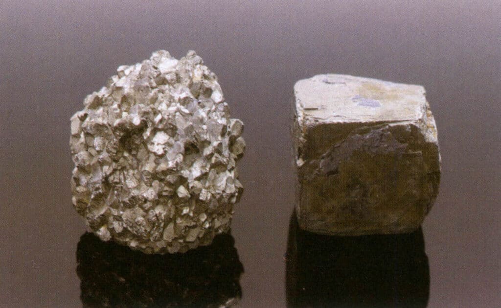
Figure 2-1-31 Pyrite Crystals (the left shows multiple pyrite crystals growing together, and the right shows a single pyrite crystal)
This section mainly discusses the crystal face patterns in the real form of crystals.
Theoretically, crystal planes are smooth and flat. Still, during the actual growth or dissolution of crystals, the surface often leaves behind slightly uneven regular patterns, commonly called crystal face patterns. Crystal face patterns include growth striation, growth layers, spiral patterns, growth hillocks, and etch figures. The crystal face patterns discussed in this book mainly refer to the crystal face stripes and etch figures that can be observed with the naked eye or under low magnification conditions.
The crystal face stripes refer to a series of parallel straight lines on the crystal surface due to the repeated convergence and alternating growth of different single forms. Also known as “combinate stripes,” these are only seen on crystal surfaces, also called growth stripes. For example, quartz’s hexagonal prismatic crystal face often has hexagonal prismatic and rhombic dodecahedral fine crystal faces alternatively developed into aggregate transverse stripes (Figure 2-1-32).

Etch figures refer to the specific-shaped pits (i.e., etch pits) left on the crystal face due to corrosion after the crystal has formed. The etch figures are controlled by the arrangement of elemental particles within the crystal face. Thus, the shapes and orientations of etch figures vary among different minerals and single forms of the same crystal. For instance, the etch figures on different single forms of diamond crystals vary; triangular pits can be seen on octahedral crystals (Figure 2-1-33), quadrilateral pits on cubic faces, overlapping quadrilateral pits form a grid-like pattern, and line patterns or microscopic disc-like patterns can be seen on rhombic dodecahedra (Figure 2-1-34).
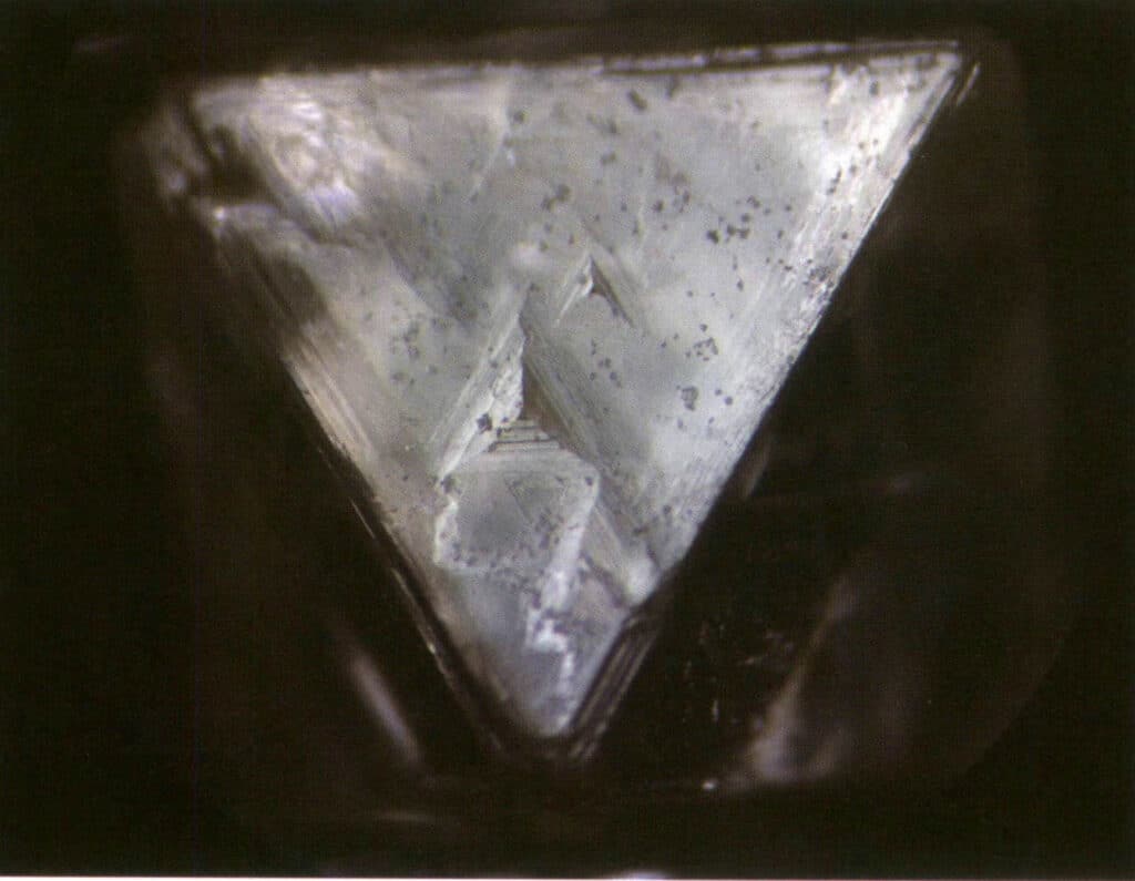
Figure 2-1-33 Visible inverted triangular pits on the diamond octahedral crystal
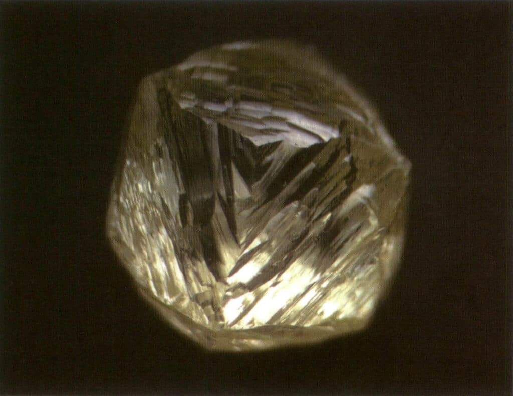
Figure 2-1-34 Linearly patterned texture visible on diamond-shaped dodecahedral crystals
Only the etch figures on the same crystal face of the same form can be the same, so etch figures are often used to identify minerals and determine whether the crystal faces belong to the same single form (Figure 2-1-35 to Figure 2-1-42).
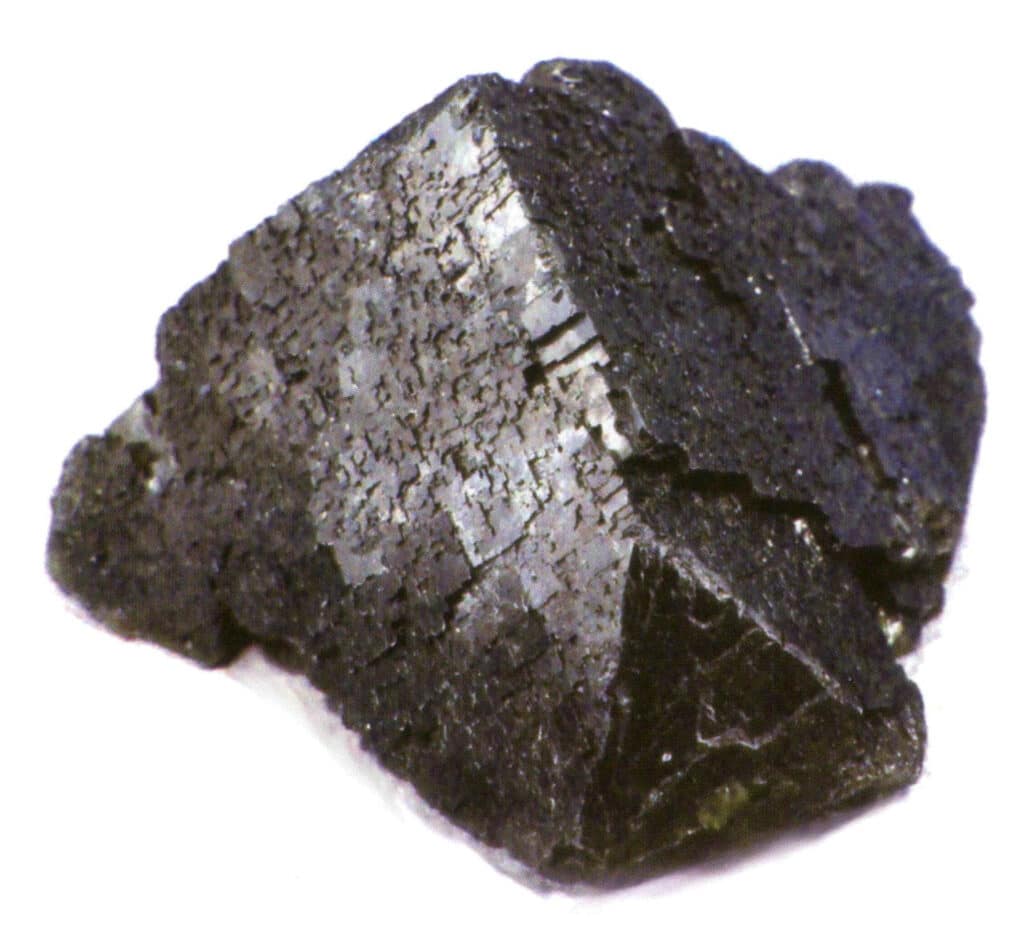
Figure 2-1-35 Fluorite crystal inlaid wood floor style stripes
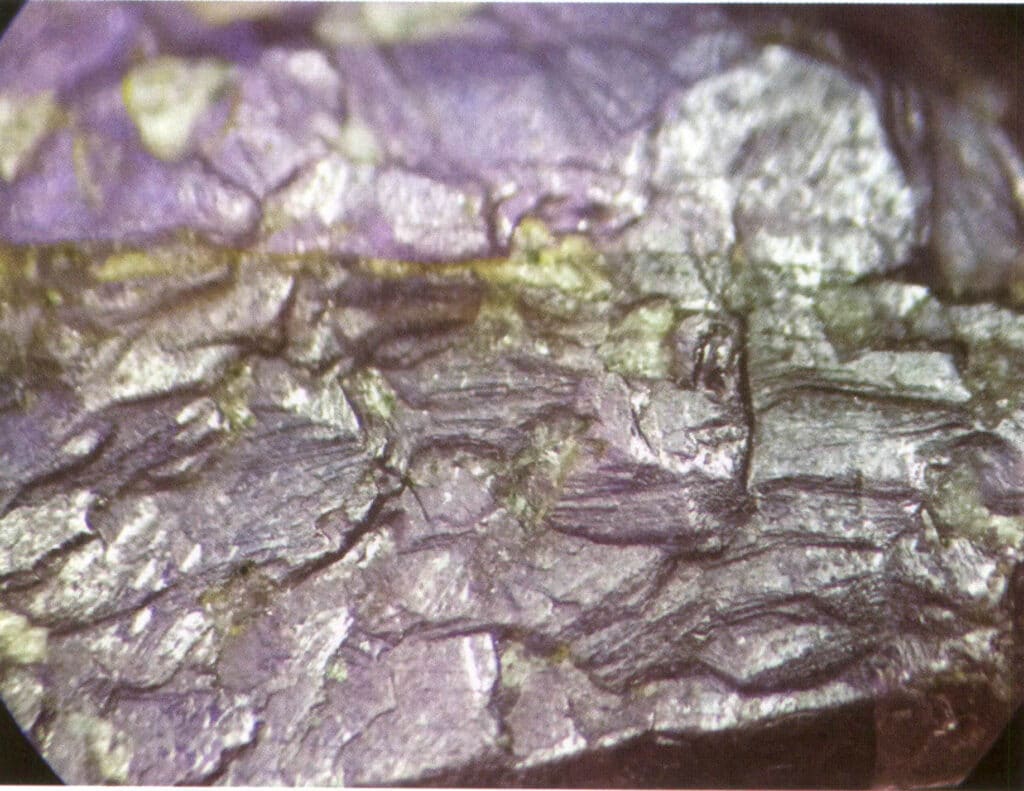
Figure 2-1-36 Natural triangular etch figure in ruby (common horizontal stripes in rubies, growth lines parallel to the rhombohedral direction, natural etchings in triangular or hexagonal shapes)
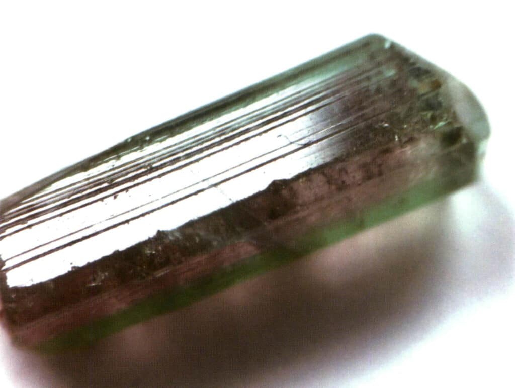
Figure 2-1-37 Surface longitudinal stripes of tourmaline
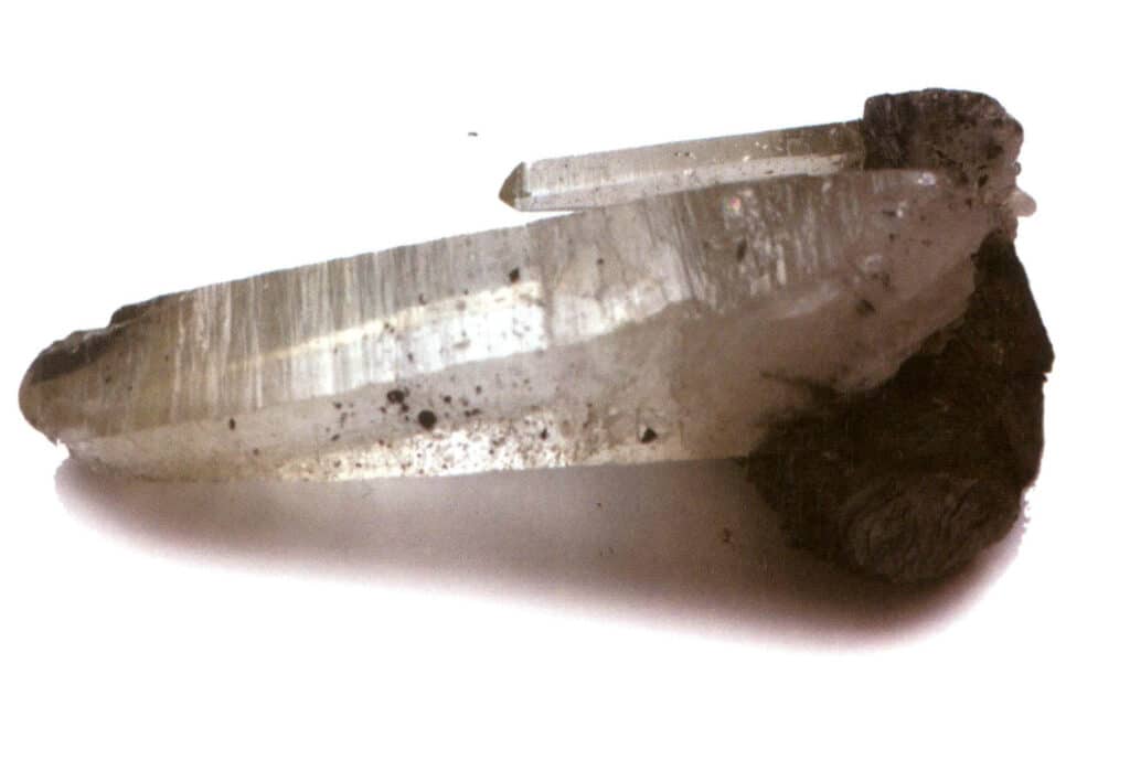
Figure 2-1-38 horizontal stripes on the surface of the crystal
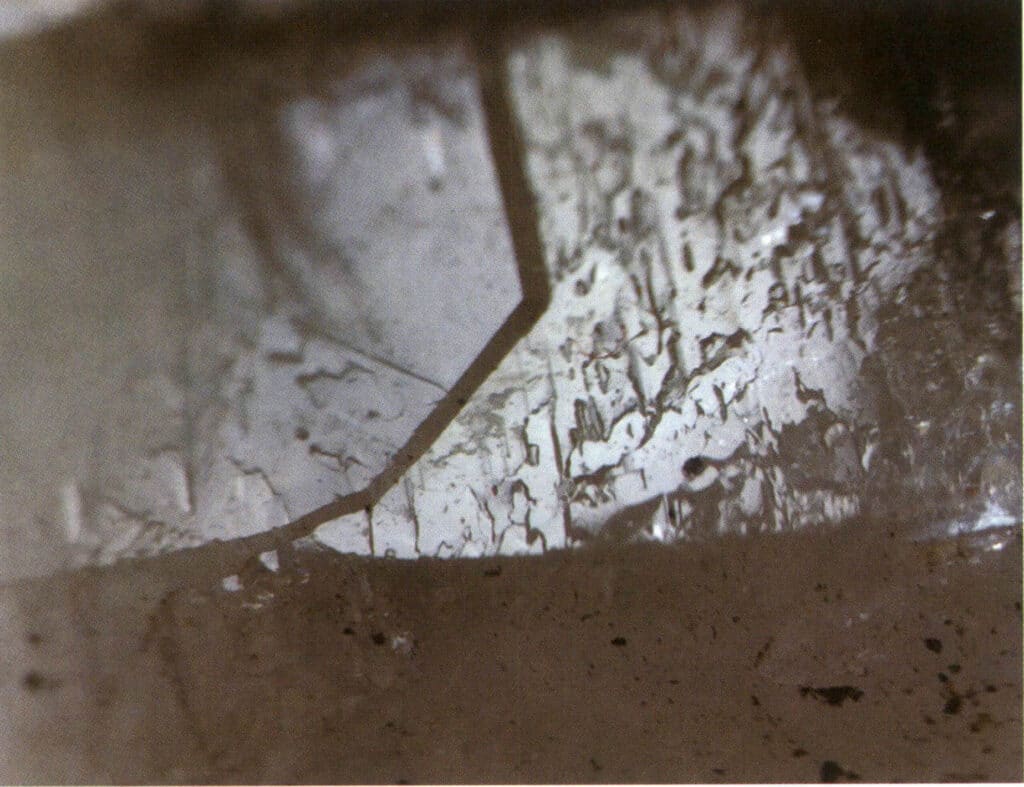
Figure 2-1-39 Etch figures on the surface of the crystal
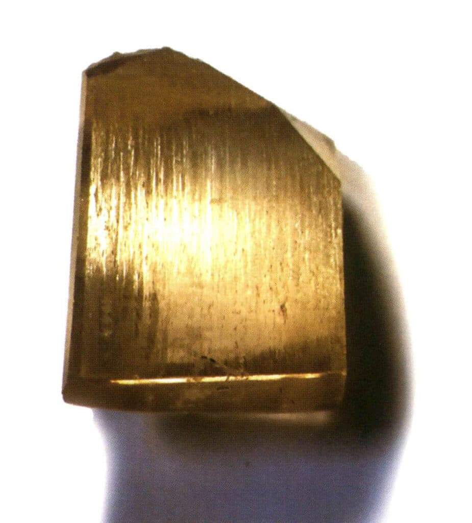
Figure 2-1-40 Surface Longitudinal Striations of Topaz

Figure 2-1-41 Topographic image of a topaz crystal
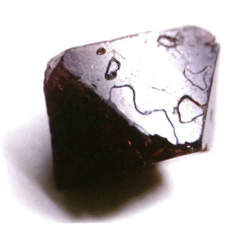
Figure 2-1-42 Etch figures of Spinel
Section II 47 Types of Crystal Forms
There are 146 different single forms in crystallography, which can be classified into 47 geometric forms based on their geometric shapes when existing independently. These geometric forms are named in the following ways:
① Named according to the characteristics of the cross-sectional shape, such as trigonal prism, tetragonal prism, hexagonal prism, rhombohedral bipyramid, etc.
② Named according to the shape of the single form, such as cylinder, double cone, cube, etc.
③ Named according to the number of geometric faces, such as single face, octahedron, etc.
④ Named according to the shape of the geometric faces, such as rhombohedron, pentacontahedron, etc.
In crystallography, single forms are divided into four categories: general forms and special forms, closed forms and open forms, regular forms and irregular forms, left-handed forms, and right-handed forms. This chapter will briefly discuss closed forms and open forms.
Closed forms refer to those whose crystal faces can enclose a closed space, divided into three main categories: polyhedral classes, skew polyhedral classes, and bipyramidal classes, totaling 30 types. Each category has more detailed classifications; for example, the polyhedral class is subdivided into tetrahedral class, octahedral class, cubic class, etc. (Figures 2-1-43 to 2-1-48)
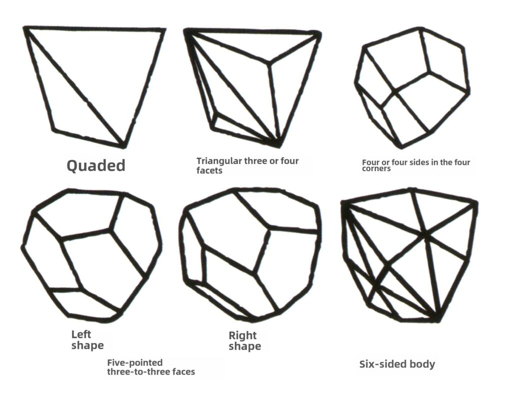
Figure 2-1-43 Tetrahedron Class
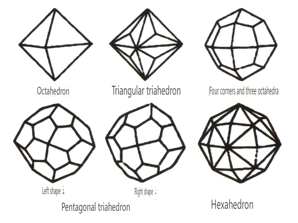
Figure 2-1-44 0ctahedral Class
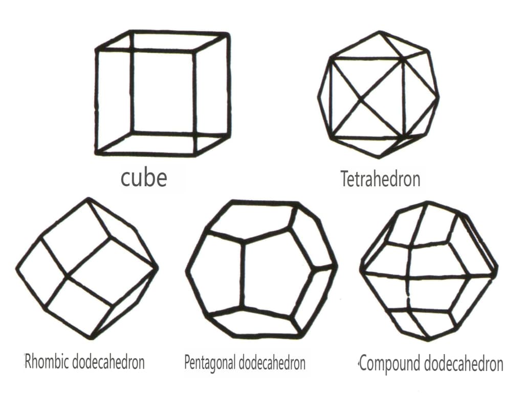
Figure 2-1-45 Cubic and Dodecahedral Classes
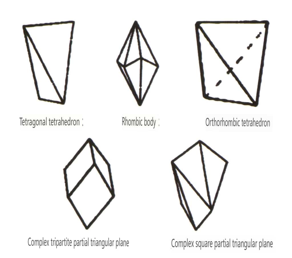
Figure 2-1-46 Other Polyhedral Types
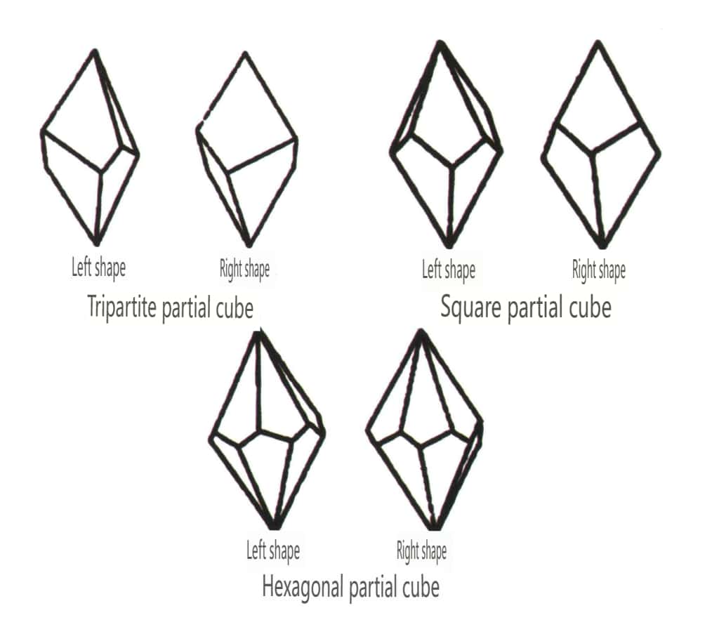
Figure 2-1-47 Oblique combinate form Class
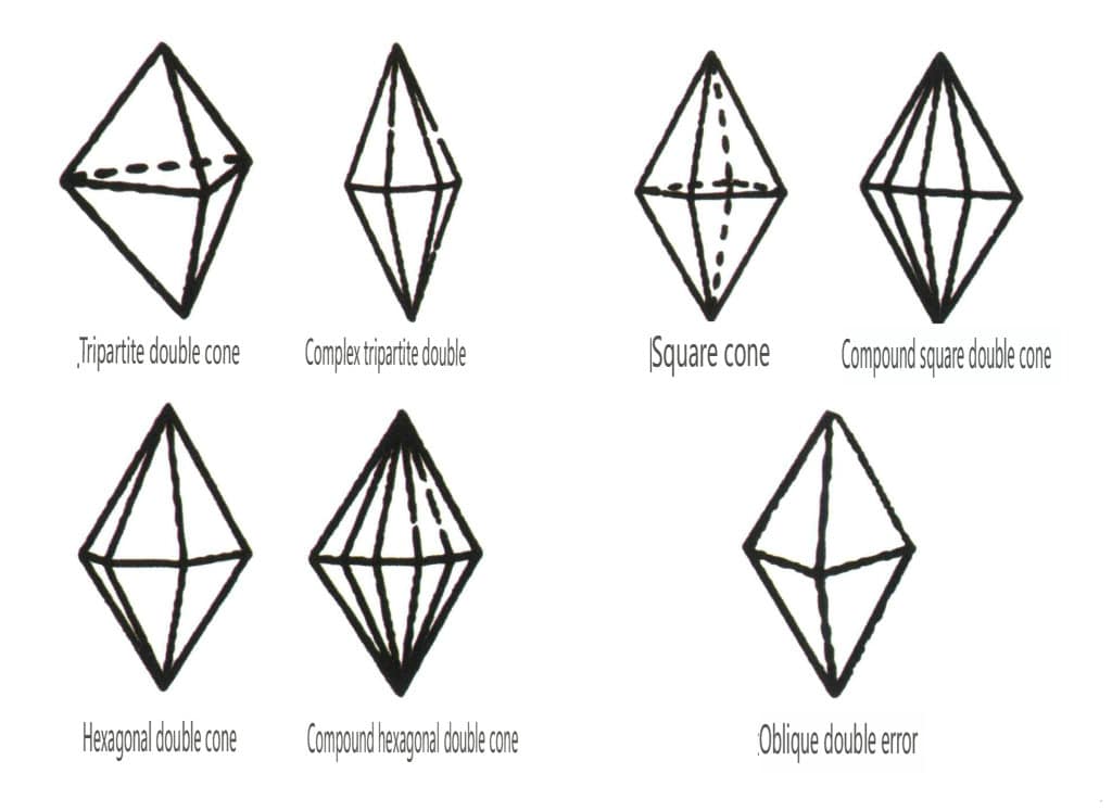
Figure 2-1-48 Double pyramidal class
Open forms refer to those whose crystal faces cannot enclose a closed space, divided into four main categories: single face, double face, columnar classes, and single pyramidal classes, totaling 17 types (Figures 2-1-49 and 2-1-51)
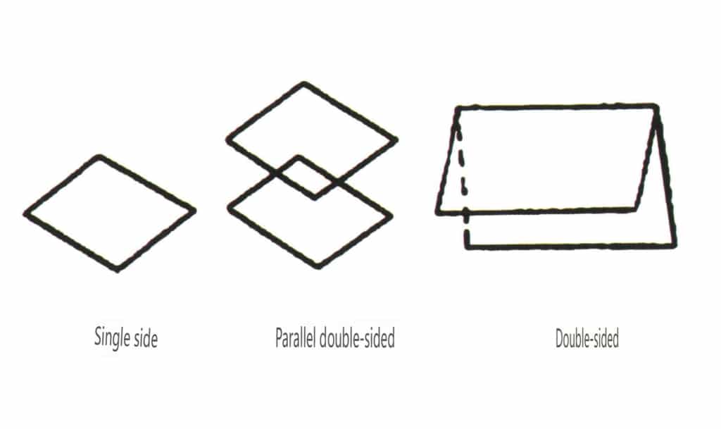
Figure 2-1-49 Single-sided and double-sided
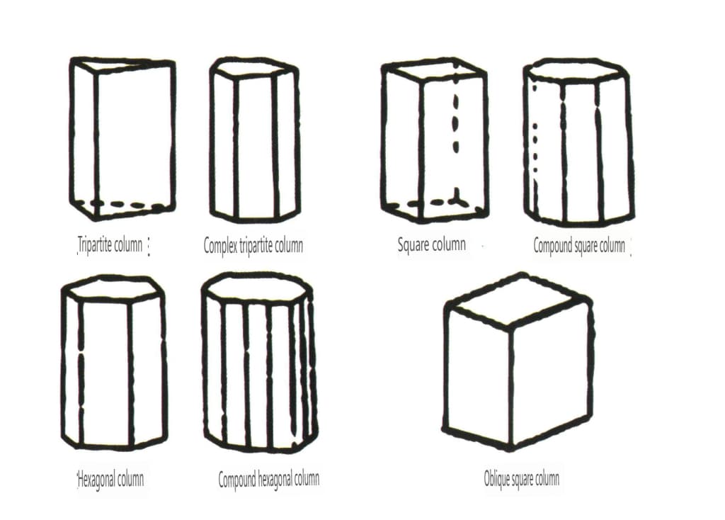
Figure 2-1-50 Columns
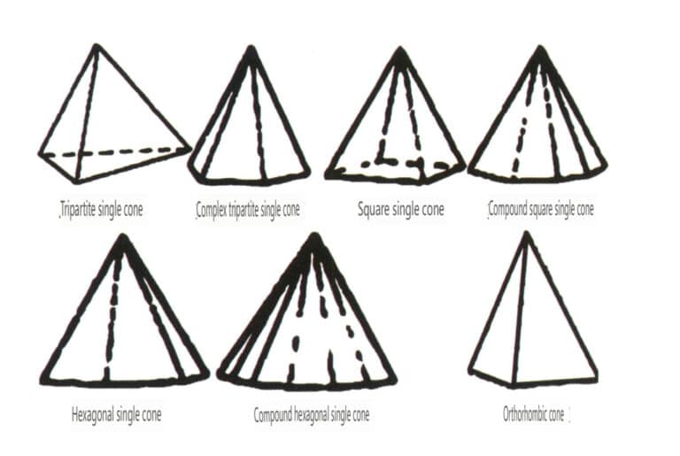
Section III Classification of Crystals
1. Symmetry of Crystals
Symmetry is an abstract concept involved in studying real crystals and unprocessed gemstone materials. It describes the repetition exhibited when the crystal structure is referenced by a direction or plane that passes through it. This is the basis for the classification of crystals.
The symmetry of a crystal can be understood from a microscopic perspective as a method to describe the repetitiveness of the crystal structure and from a macroscopic perspective as the repetition of two or more geometric faces that are the same in shape and size but may differ in direction, according to certain rules. This pattern of repetition can be described using symmetry axes and planes of symmetry, with each symmetry axis or plane of symmetryreferred to as a symmetry element. When observing or inferring the symmetry of an object, this action is described as performing operations on symmetry.
2. Symmetry Elements of Crystals
In crystallography, there are four symmetry elements: axis of symmetry, plane of symmetry, rotoinversion symmetry axes, and symmetrical center. This will involve the two symmetry elements of axis of symmetry and plane of symmetry.
2.1 Axis of Symmetry
(1) The concept of axis of symmetry and their notation.
The axis of symmetry is an imaginary straight line that indicates the number of times the base level (Figures 2-2-1 to Figure 2-2-2) appears in the same position when the lattice structure is rotated 360° around this imaginary line. This number can only be 2, 3, 4, or 6 times in 4 cases. It can also be understood as an imaginary line passing through the center of the geometric body, rotating the geometric body along this line 360°. Suppose the shape of the geometric body after rotating a certain angle is consistent with the shape of the geometric body at the initial zero degrees. In that case, this imaginary line is called the axis of symmetry.
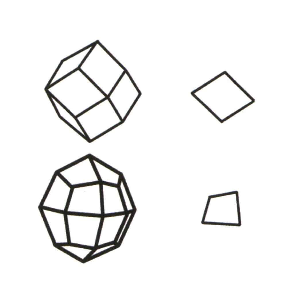
Figure 2-2-1 Selection of the base level for the single form.
The base level of single form is the smallest repeating plane that makes up the simplex. The upper left of the figure shows a rhombic dodecahedron, which is a closed shape composed of one type of face. The smallest repeating plane is the rhombus shown in the upper right, so the base level for the rhombic dodecahedron is the rhombus. The lower left in the figure shows a quadrilateral octahedron, which is a closed shape composed of one type of face. The smallest repeating plane is the quadrilateral shown in the lower right, so the base level for the quadrilateral octahedron is the quadrilateral.
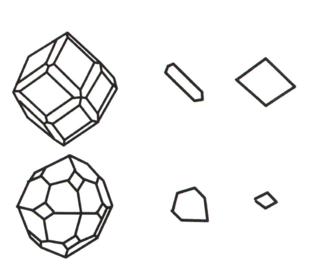
Figure 2-2-2 Selection of the base level for the polytope.
The aggregation of multiple simple forms forms a combinate form, and the choice of the base level for the combinate form is the judgment of the single form that combine to form the combinate form. The first column from the left in the figure represents a combinate form (formed by the aggregation of single forms of a dodecahedron and a tetrahedron), and this geometric body is a closed figure composed of two types of faces. The hexagon represents the minimum repeating plane in the second column and the rhombus on the right in the third column. Hence, the base level for the combinate form in the first column is either the hexagon or the rhombus. When calculating the axis of symmetry, only one shape can be selected as the base levelfor symmetry recording.
The axis of symmetry is represented by the uppercase letter L, with the order of the axis n written in the upper right corner of L, written as Lⁿ. For example, a 2-fold axis is represented as L², a 3-fold axis as L³, a 4-fold axis as L⁴, and a 6-fold axis as L⁶. L⁶, L⁴, L³ is habitually referred to as a axis of the higher order.
Crystals may have axes of symmetry in different directions, and the number of these non-coinciding symmetry axes is conventionally written to the left of L. For example, six secondary axes are represented as 6L² (Figure 2-2-3 to Figure 2-2-9), three tertiary axes are represented as 3L³ (Figure 2-2-10 to Figure 2-2-14), four tertiary axes are represented as 4L³ (Figure 2-2-15 to Figure 2-2-18), and one hexagonal axis is represented as L⁶ (Figure 2-2-19).
When a crystal has multiple axes of symmetry, the recorded method arranges them from left to right in descending order, with the number of symmetry axes written on the left side of the corresponding axis, for example, L⁶6L², 3L⁴4L³6L².
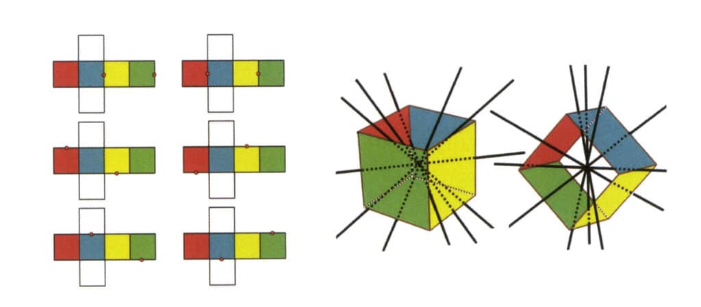
Figure 2-2-3 Secondary Axis of the Cube
The left side of the figure shows the unfolded view of a cube, with red dots indicating the intersection points of the imaginary line and the edges. The right side of the figure shows a closed cube, where the secondary axis may appear at the midpoint of parallel edge lines, the midpoint of parallel rectangular faces, or the intersection points of three or more parallel faces resembling a rectangle.
Copywrite @ Sobling.Jewelry - Producent biżuterii na zamówienie, fabryka biżuterii OEM i ODM
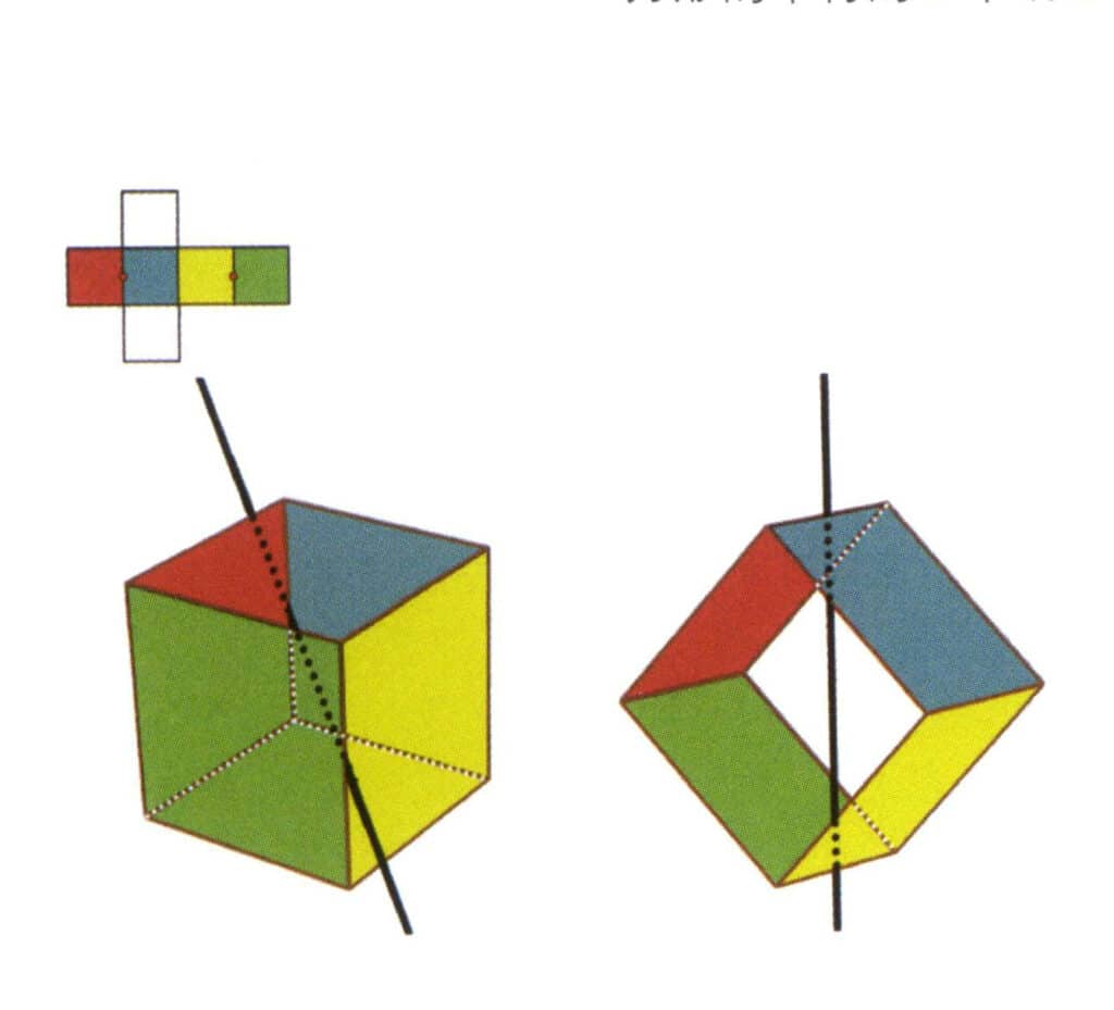
Figure 2-2-4 The first secondary axis of the cube
Select the midpoint of the parallel lines, as shown in the figure. Imagine a straight line passing through the midpoints of these two edges, rotating the cube by 360°. The base levels with different colors but the same shape will repeat twice in the same position (the red and blue faces, the yellow and green faces, the two colorless faces, and three sets of repeated faces. Although three sets of repeated faces will appear since the imaginary line has not changed in position and angle, the secondary axis is recorded only once). This imaginary line is recorded as the secondary axis.
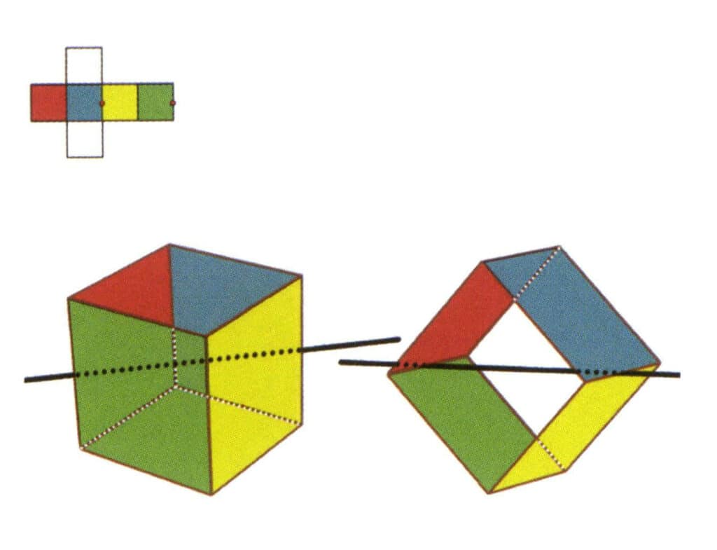
Figure 2-2-5 The second secondary axis of the cube
Select the midpoint of the parallel lines, as shown in the figure. Imagine a straight line passing through the midpoints of these two edges, rotating the cube by 360°. The base levels with different colors but the same shape will repeat twice in the same position (the red and green faces, the yellow and blue faces, the two colorless faces, and three sets of repeated faces). This imaginary line is recorded as the second secondary axis.
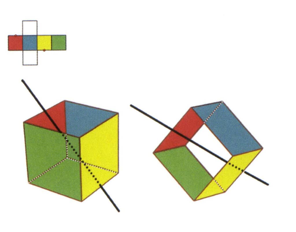
Figure 2-2-6 The third secondary axis of the cube.
Select the midpoint of the parallel lines, as shown in the figure. Imagine a straight line passing through the midpoints of these two edges, rotating the cube by 360°. The base levels with different colors, but the same shape will repeat twice in the same position (the red and colorless faces, the green and blue faces, the colorless and yellow faces, three sets of repeated faces). This imaginary line is recorded as the third secondary axis
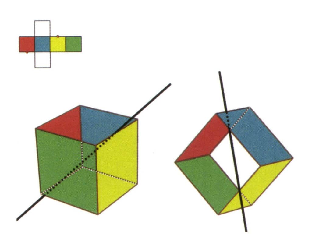
Figure 2-2-7 The fourth secondary axis of the cube
Select the midpoint of the parallel lines as shown in the figure, imagine a straight line passing through the midpoints of these two edges, and rotate the cube 360°; the differently colored but identically shaped reference planes will repeat in the same position twice (the red and colorless faces, the green and blue faces, the colorless and yellow faces, three sets of repeated faces), this imaginary straight line is recorded as the fourth secondary axis.
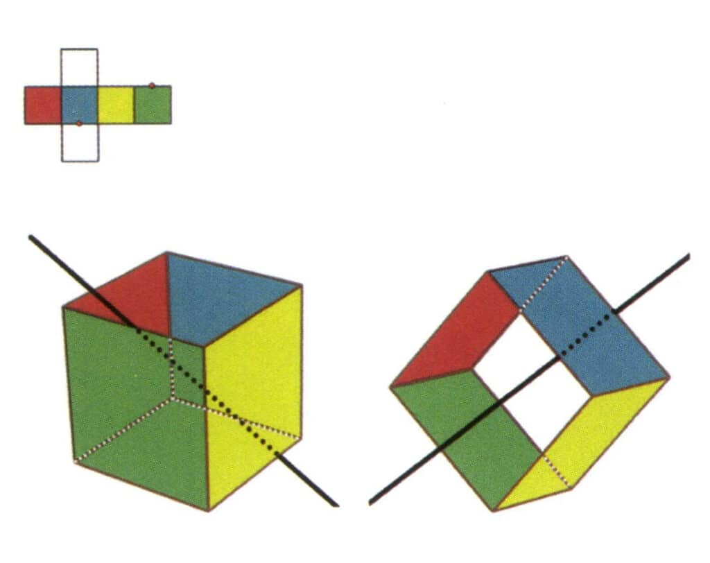
Figure 2-2-8 The fifth secondary axis of the cube.
Select the midpoints of the parallel lines as shown in the figure, imagine a straight line passing through the midpoints of these two edges, rotate the cube 360°, the differently colored but identically shaped reference planes will repeat in the same position twice (red and colorless faces, green and blue faces, colorless and yellow faces, three sets of repeated faces), this imagined straight line is recorded as the fifth secondary axis.
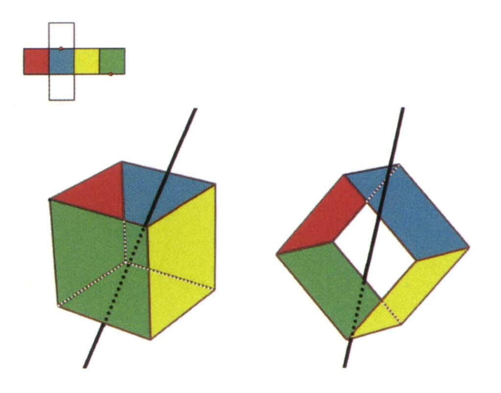
Figure 2-2-9 The sixth secondary axis of the cube
Select the midpoint of the parallel lines, as shown in the figure. Imagine a straight line passing through the midpoints of these two edges, rotating the cube by 360°. The differently colored but identically shaped base levelswill repeat in the same position twice (green and colorless faces, red and yellow faces, colorless and blue faces, three sets of repeated faces). This imaginary line is recorded as the sixth secondary axis.
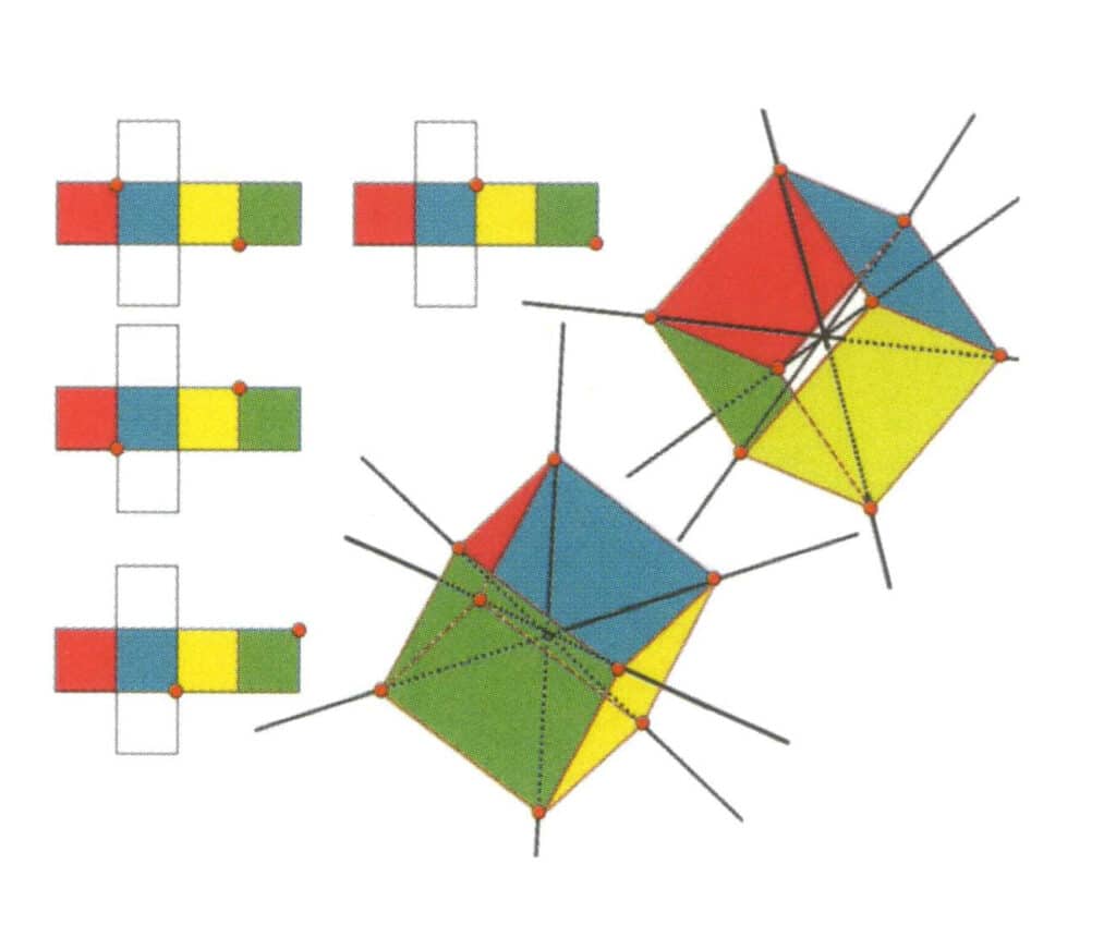
Figure 2-2-10 The tertiary axis of the cube
The left side of the figure shows the unfolded view of the cube, with the red dot indicating the intersection point of the imaginary line and the edge line. The right side of the figure shows the closed cube; the red points indicate the intersection of the imaginary straight line and the edges. The tertiary axis may appear at the midpoint of the faces of a parallel equilateral triangle, at the intersection of three or more parallel faces resembling an equilateral triangle.
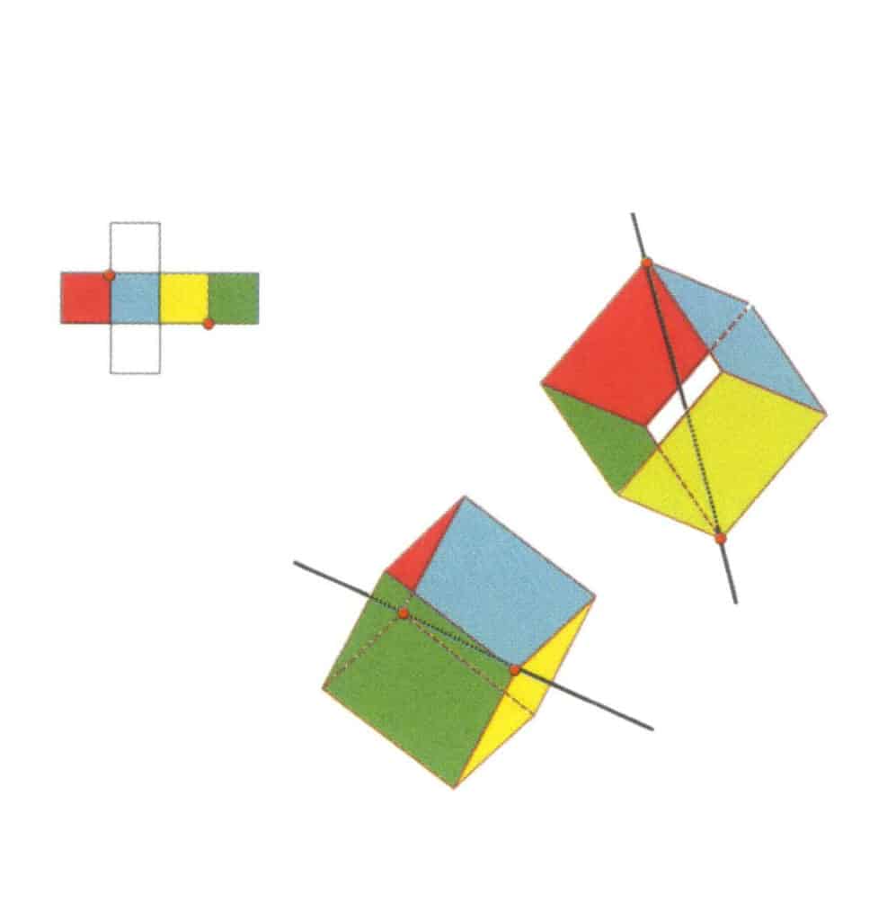
Figure 2-2-11 The first tertiary axis of the cube.
Select the intersection points of the three faces as shown in the figure, imagine a straight line passing through the midpoints of these two edges, rotate the cube 360°, the differently colored but identically shaped reference planes will repeat in the same position three times (red, colorless, and blue faces, green, colorless, and yellow faces, two sets of repeated faces), this imagined straight line is recorded as the first tertiary axis
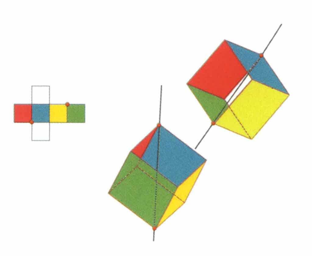
Figure 2-2-12 The second tertiary axis of the cube.
Select the intersection points of the three faces, as shown in the figure. Imagine a straight line passing through the midpoints of these two edges, rotating the cube by 360°. The differently colored but identically shaped base levels will repeat in the same position three times (red, colorless, and blue faces; green, colorless, and yellow faces, two sets of repeated faces). This imaginary line is recorded as the second tertiary axis.
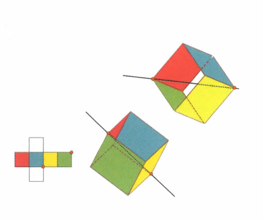
Figure 2-2-13 The third tertiary axis of the cube
Select the intersection points of the three faces, as shown in the figure. Imagine a straight line passing through the midpoints of these two edges, rotating the cube by 360°. The differently colored but identically shaped base levels will repeat in the same position three times (red, colorless, and green faces; blue, colorless, and yellow faces, two sets of repeated faces). This imaginary line is recorded as the third tertiary axis.
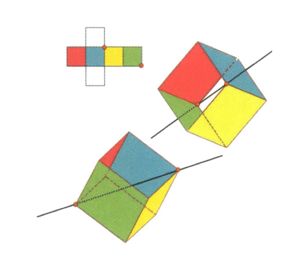
Figure 2-2-14 Fourth cubic axis of the cube.
Select the intersection of the three faces as shown in the figure, assuming there is one straight line through the midpoint of the two edges rotates the cube 360°, different colors but the same shape base level will be the same. Repeat the position three times (red, colorless, green face, blue, colorless, and yellow faces, two sets of repeated faces). This imaginary line is recorded as the fourth cubic axis.
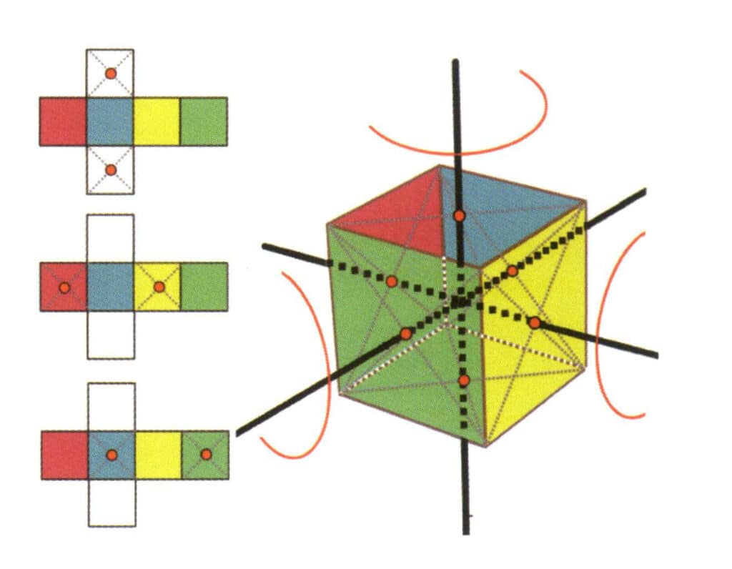
Figure 2-2-15 Fourth Axis of the Cube
The left side of the figure shows the unfolded view of the cube, with the red dots indicating the intersection points of the imaginary line and the edges. The right side of the figure shows a closed cube, with the red dots indicating the intersection points of the imaginary line and the plane. The fourth axis may appear at the midpoint of parallel square faces, at the intersection of three or more parallel faces that resemble a square.
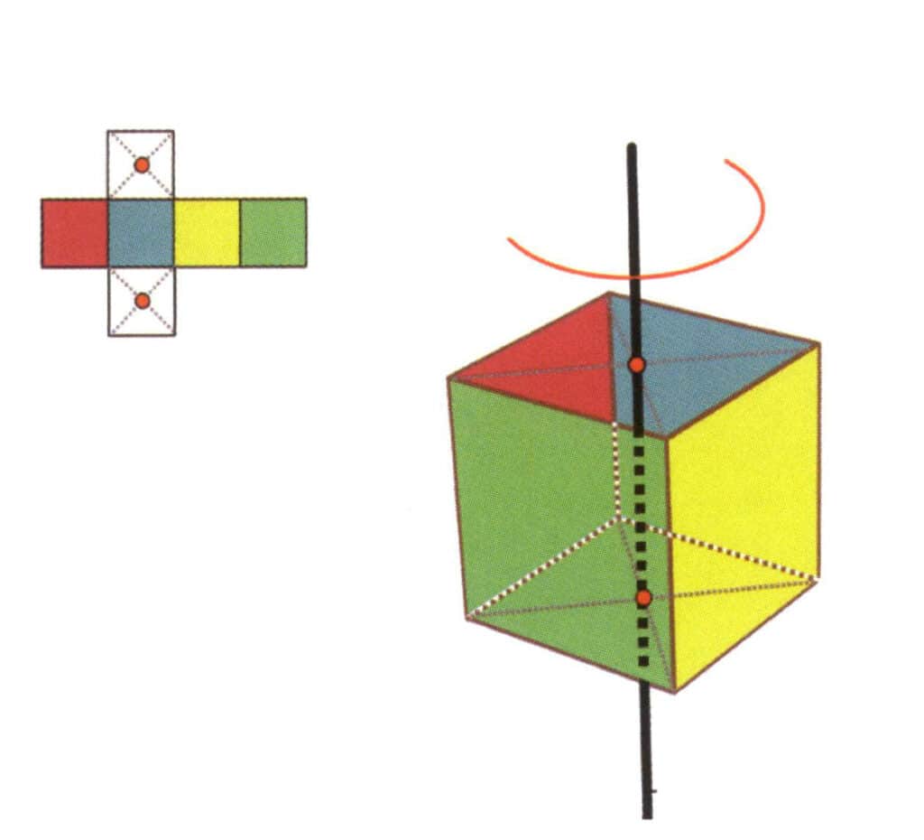
Figure 2-2-16 The first quartic axis of the cube
Choose the midpoints of the planes shown in the figure, assume that there is a straight line through the midpoints of the two planes, and rotate the cube by 360°. The different colored but same-shaped base level faces will be repeated in the same position four times (red, blue, green, and yellow faces), and this hypothetical straight line is recorded as a quadruple axial.
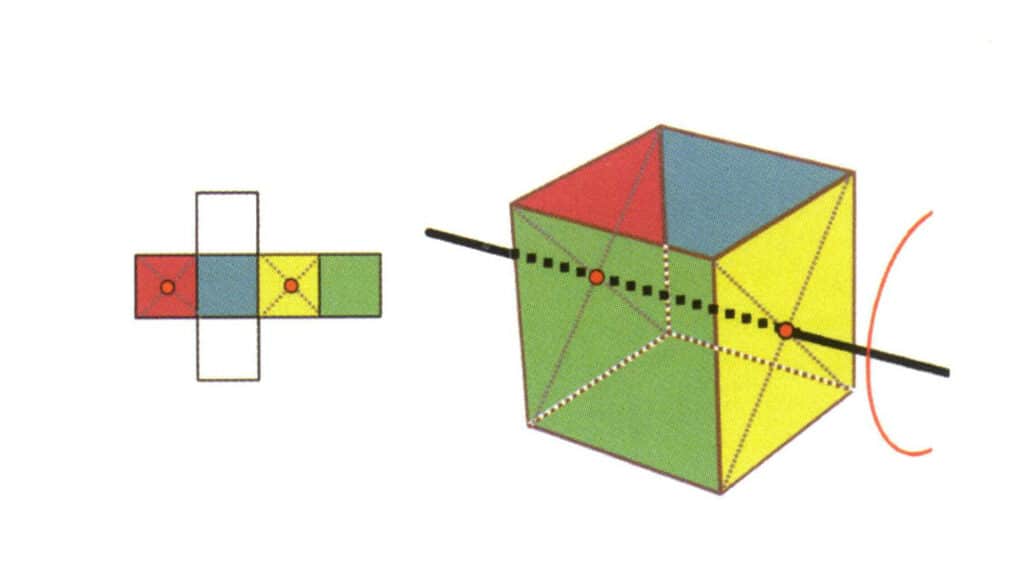
Figure 2-2-17 The second quartic axis of the cube
Select the midpoint of the plane as shown in the figure, imagine a straight line through the cube, and rotate the cube 360°; the base level surface of different colors but the same shape will be repeated four times in the same position (colorless, blue face on the top, colorless, green face on the bottom), and this imaginary line will be recorded as the second quadric axis.
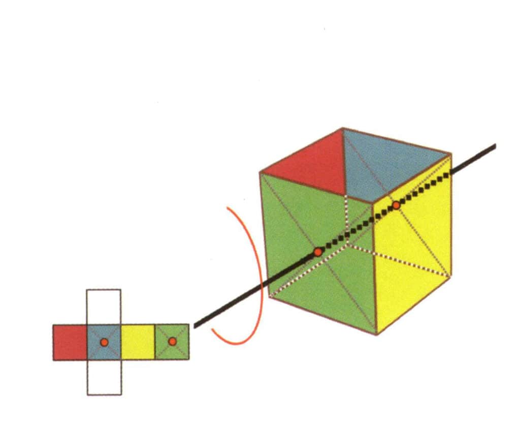
Figure 2-2-18 Third quartic axis of the cube
Select the midpoint of the plane as shown in the figure, imagine a straight line through the cube, and rotate the cube 360°. The base level of different colors but the same shape will be repeated four times in the same position (colorless, red face on the top, colorless, yellow face on the bottom), and this imaginary line will be recorded as the third, fourth axis
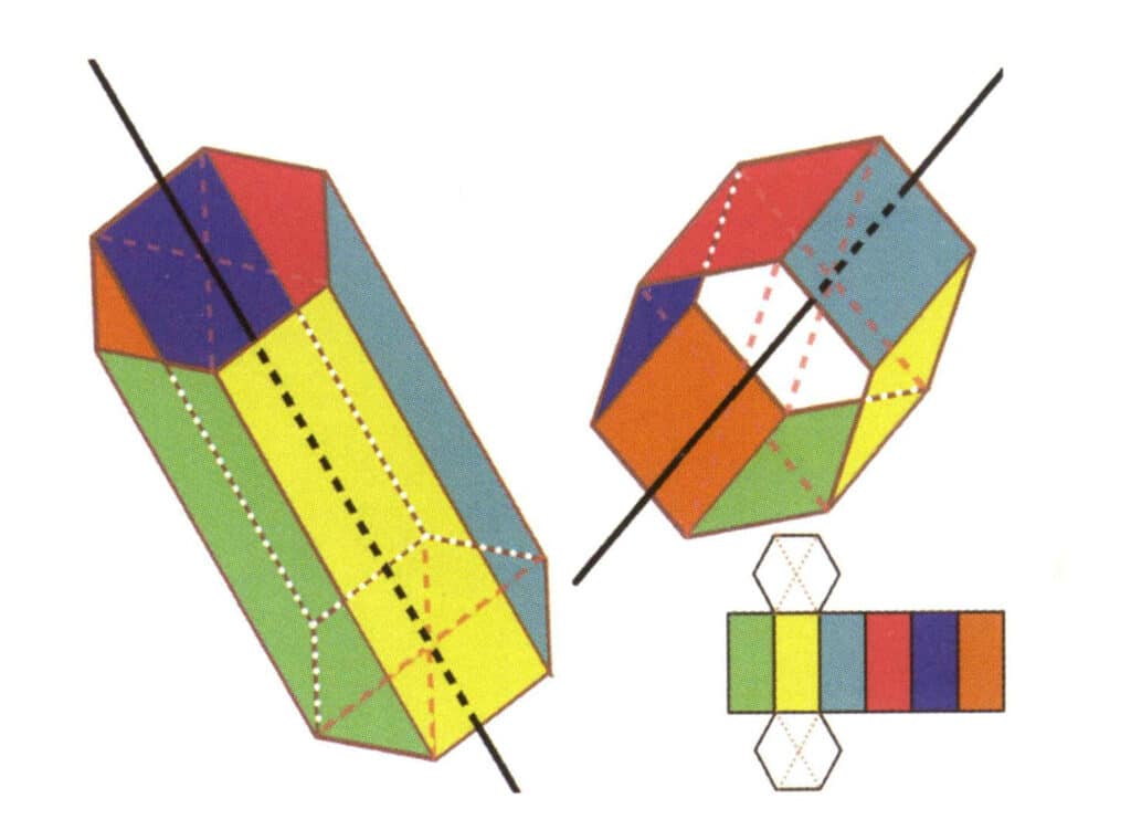
Figure 2-2-19 Six axes of a hexagonal prism
The black lines on the left and top right represent the six axes of the hexagonal prism. The lower right is an expansion of the hexagonal prism The sextic axis may appear at the midpoint of the faces of a parallel hexagon or the intersection of the six faces of a hexagon.
(2) Considerations for finding the axis of symmetry.
① There are five types of positions for the axis of symmetry.
The midpoint of two parallel edges, such as the position of the secondary axis of a cube.
The midpoint of two parallel planes, such as the position of the quartic axis of a cube.
Between two vertices (the intersection points of multiple faces), such as the position of the tertiary axis of a cube.
The midpoint between a vertex and a parallel plane, such as the position of the tertiary axis of a tetrahedron.
The midpoint of the edge line and the midpoint of the parallel plane, such as the secondary axis position of a triangular prism.
② The Selection of the symmetry axis in the same direction follows the principle of the lowest number. For example, according to the lowest principle, if one direction finds six axes of symmetry and three axes of symmetry, it will ultimately be recorded as L³. The axes of symmetry in different directions should be recorded according to the number found.
It should be noted that except for the six-fold axis of symmetry and the four-fold axis of symmetry, which cannot appear simultaneously, and only one six-fold axis can appear, other axes of symmetry can coexist in various forms or multiple instances.
③ The base level must be selected as the smallest unit plane; two or more intersecting planes cannot be selected as the base level. Otherwise, it will affect the accuracy of the symmetry axis judgment.
④ When recording the number of axes of symmetry, it is essential to determine the number of times the same shape and size of the plane is repeated in the same position.
⑤ If there is a secondary axis of vertical symmetry Lⁿ(n = 3, 4 or 6), there must be n secondary axes vertical to Lⁿ.
2.2 Plane of Symmetry
(1) Concept and Recording Method of Plane of Symmetry
A plane of symmetry is an imaginary plane that, when the crystal is cut along this plane, allows each half of the crystal to be a mirror image of the other half (Figure 2-2-20). In the same crystal structure, such a plane can appear a maximum of 9 times (Figure 2-2-21), meaning it can be bisected in 9 different ways, and the two halves can completely coincide. Of course, not all crystal structures have planes of symmetry.
The uppercase letter P represents the plane of symmetry. Some crystals have multiple non-coinciding planes of symmetry, and the number of these planes of symmetry is conventionally written to the left of P; for example, four planes of symmetry are represented as 4P, and one plane of symmetry is represented as P.
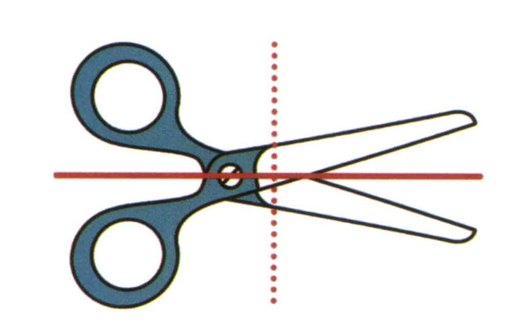
Figure 2-2-20 Imagine a vertical plane of paper and a plane extending along the direction of the red solid line, which divides the scissors into upper and lower parts, and the upper and lower parts are mirror symmetric. This imagined plane is called the plane of symmetry. Imagine another plane perpendicular to the paper surface and extending along the direction of the red dashed line, which divides the scissors into left and right parts, but the shapes of the scissors on the left and right sides are not symmetrical.

Figure 2-2-21 Nine planes of symmetry of a cube
(2) Tips for Finding Planes of Symmetry.
① The plane of symmetry is often parallel and coincident with the symmetry axis.
② The plane of symmetry is an imaginary plane that divides the crystalline geometry, which is different from the parallel double plane in geometry.
③ If a plane of symmetry contains the symmetry axis Lⁿ, then there must be n planes of symmetry containing Lⁿ.
(3) Point Group.
The point group is the sum of all symmetry elements in a crystal. The order of writing the point group is symmetry axis + symmetry plane, for example, 3L²3P (Figure 2-2-22). If a crystal has multiple symmetry axes, it is customary to record them from left to right, from axis of the higher order to axis of the lower order, and the order of planes of symmetry, for example, L⁴4L²5P (Figure 2-2-23). There are 32 types of symmetry in crystals.
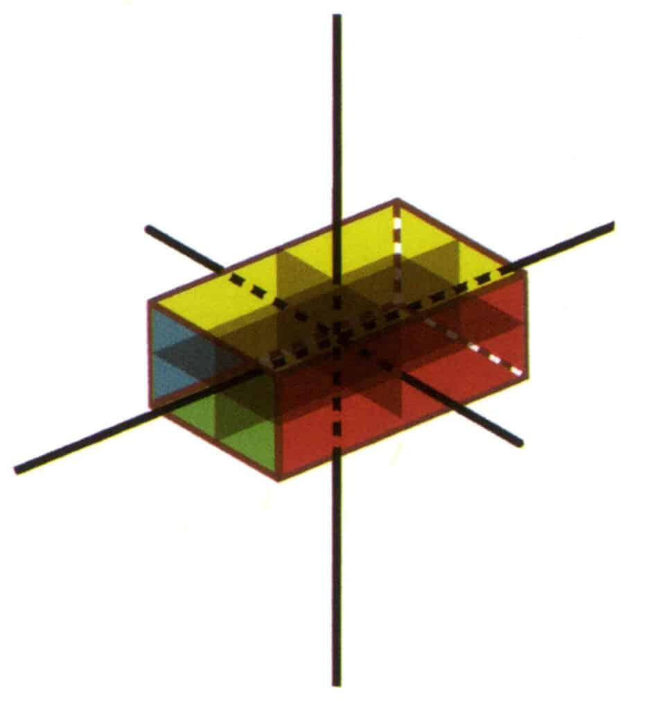
Figure 2-2-22 3L²3P point group(rectangular cuboid with a rectangular cross-section)
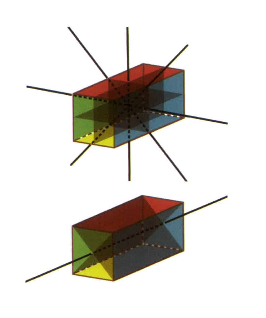
Figure 2-2-23 L⁴4L²5P point group(a rectangular prism with a square cross-section), with four second axes and three symmetrical faces on the top, and one fourth axis and two symmetrical faces on the bottom.
3. Classification of Crystals
Symmetry is a part of crystal classification. Another concept- crystal axis- needs to be introduced to describe the crystal structure of all-natural and artificial crystal gemstones in a crystal classification scheme. The crystal axis is an imaginary line through the crystal structure, indicating the direction in which the lattice nodes repeat and the relative distance in which the nodes repeat along that direction. The crystal axis coincides with the normal of the axis of symmetry or the plane of symmetry. If there is no axis of symmetry or plane of symmetry, the crystal axis can be selected in parallel with the crystal edge direction.
Based on symmetry elements and crystal axes, the academic system classifies crystals into three crystal families and seven crystal systems (Table 1).
Table 1: Key Points for Determining Crystal Families and Systems
| Crystal family | Kryształ | Key points for determination | Common Gemstone Varieties |
|---|---|---|---|
| Low-level Crystal System | Układ trójliniowy | No Second Axis or Symmetry Plane | Amazonite, rhodonite, Turquoise |
| Monoclinic Crystal System | No higher-order axes, no more than one secondary axis and symmetry plane | Jadeite, diopside, spodumene, epidote | |
| Orthorhombic crystal system | No higher-order axes, more than one secondary axis or symmetry plane | Olivine, topaz, saualpite(including tanzanite), cordierite, chrysoberyl, enstatite | |
| Intermediate Crystal Family | Tetragonal Crystal System | 1 fourfold Axis (can be represented by L4) | Diament |
| Trigonal Crystal System | 1 trigonal axes (can be represented by L3) | Corundum, ruby, sapphire, tourmaline , crystals in the quartz family (such as crystal, amethyst, citrine, etc.), rhodochrosite | |
| Sześciokątny układ krystaliczny | 1 hexagonal axis (can be represented by L6) | Aquamarine, emerald, and other berylite family gemstones, apatite | |
| Advanced crystal family | Izometryczny system kryształów | 4 trigonal axes (can be represented by 4L3) | Diamond, garnet, spinel, fluorspar |
4. Common Gemstone Crystal Characteristics
Common gemstones include diamond, spinel, fluorspar, garnet, berylite, zircon, corundum, tourmaline, crystal, chrysoberyl, topaz, etc. Each type of gemstone has its own fixed crystal characteristics.
High-level crystal family gemstones are mostly granular in crystal habit, and common varieties often appear in fixed crystal forms (Table 2).
The crystal habit of intermediate and low-level crystal families is columnar (Table 3).
Table 2: Common crystal characteristics of high-level crystal families
| Gems tone Name | Crystal Classification | Important Crystal Characteristics | |||
|---|---|---|---|---|---|
| Gems tone Name | Crystal Classification | Crystal Habit | Common crystal forms | Common twin forms | Common crystal face patterns |
| Diament | Izometryczny system kryształów | Granular crystal habit (Figure 2-2-24), commonly seen in octahedral granules | The octahedron is a common crystal form, and more complex crystal shapes, including rhombic dodecahedra, can also appear, often featuring rounded crystal faces, which can exhibit threefold symmetry | Triangular flat twin, sometimes without visible concave angles (Figure 2-2-25) | The surface shows inverted triangular etch pits (Figures 2-2-26, 2-2-27) and other crystal face patterns (Figures 2-2-28, 2-2-29) |
| Spinel | Granular crystalline habit (Figure 2-2-30), commonly seen in octahedral granules | Often produced in octahedral form, the crystal faces can be very flat, appearing as if polished (Figure 2-2-31) | The twin crystals are very flat, resembling a triangular shape with corners cut off (Figure 2¬2-32) | Surface-visible etching pits, some resembling diamonds in an inverted triangle shape (Figure 2-2-33) | |
| Fluoryt | Granular crystal habit (Figure 2-2-34) | Octahedral and cubic crystal shapes (Figure 2-2-35) | Interpenetrating twinning | Square step growth marks, mostly with cleavage gaps, color bands parallel to the directions of the six faces of the cube | |
| Granat | Granular crystalline habit, commonly seen in rhombic dodecahedral grains (Figure 2-2-36) | Rhombic dodecahedron or square-trapezohedron | Rzadki | Concentric ring bands visible with the same shape as the crystal faces (Figure2-2-37) | |
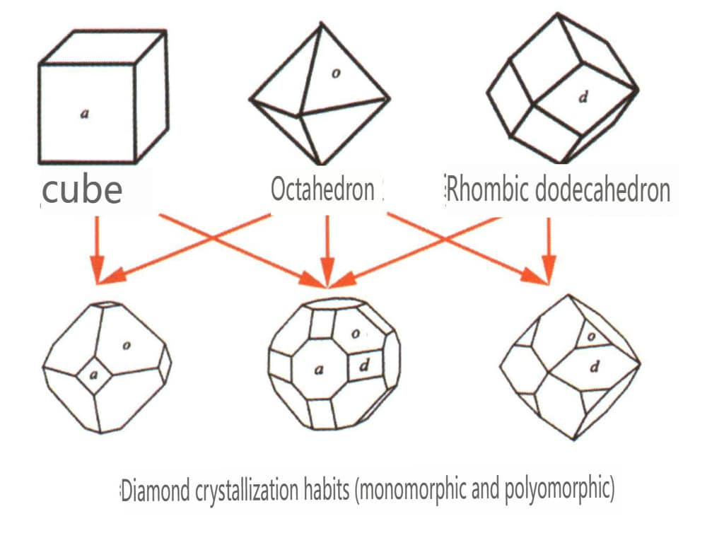
Figure 2-2-24 Diamond crystal habits
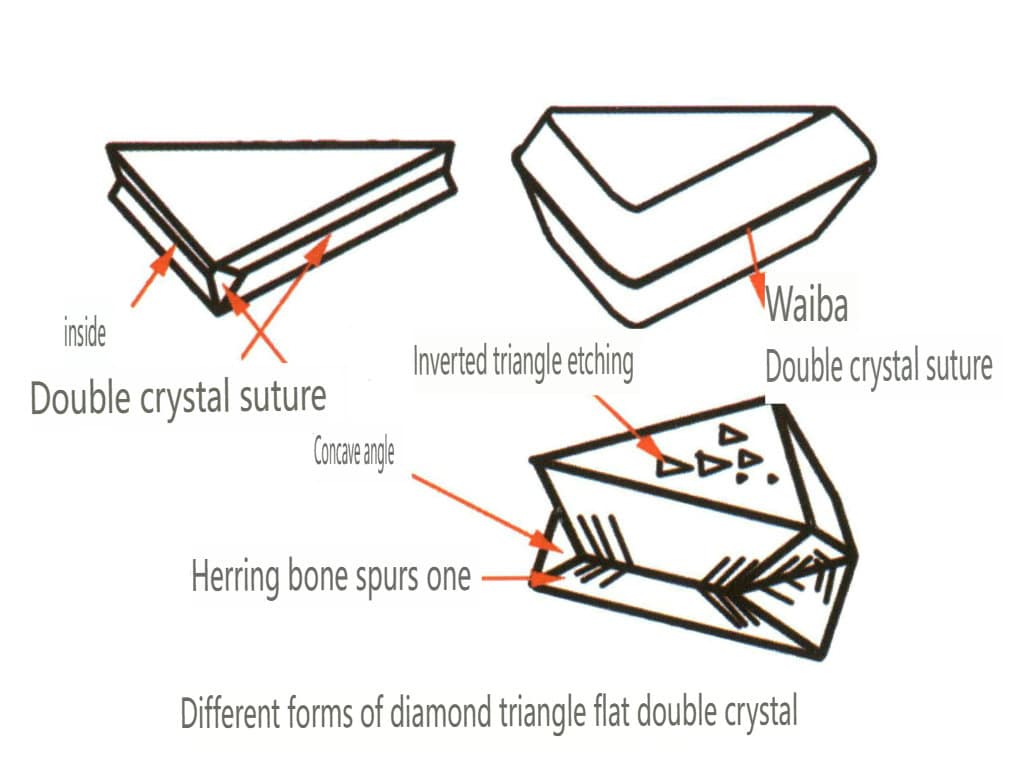
Figure 2-2-25 Diamond Twin Habit
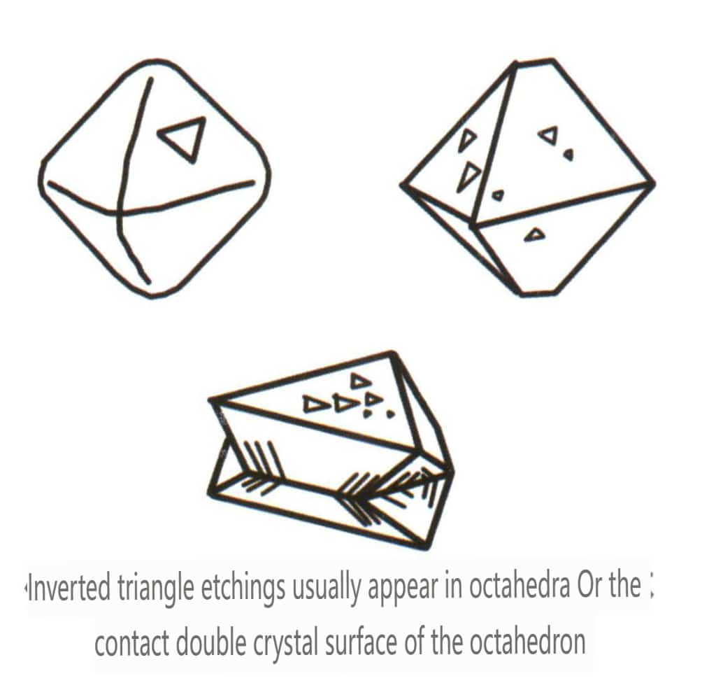
Figure 2-2-26 Inverted Triangle etch figure of Diamond Octahedral Crystal Faces
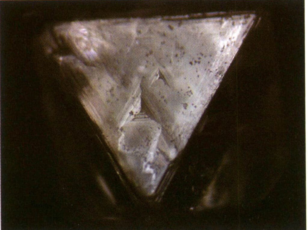
Figure 2-2-27 Inverted triangular etch figure on the surface of a diamond octahedral crystal
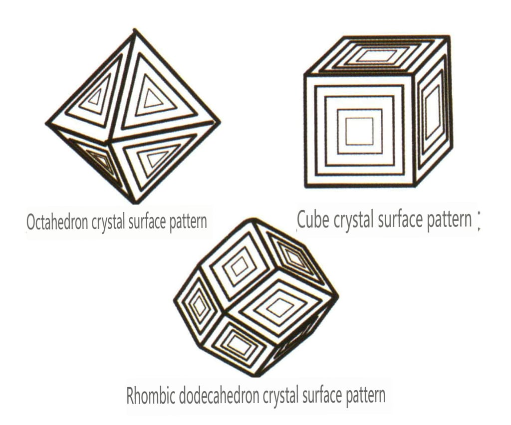
Figure 2-2-28 Inverted Triangle etch figure of Diamond Octahedral Crystal Faces
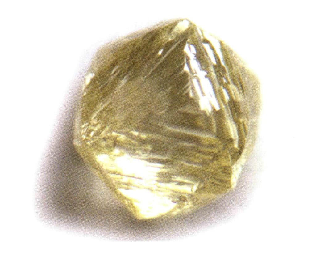
Figure 2-2-29 Inverted triangular etch figure on the surface of a diamond octahedral crystal
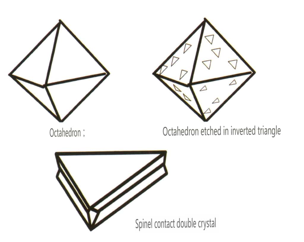
Figure 2-2-30 Spinel crystal habit
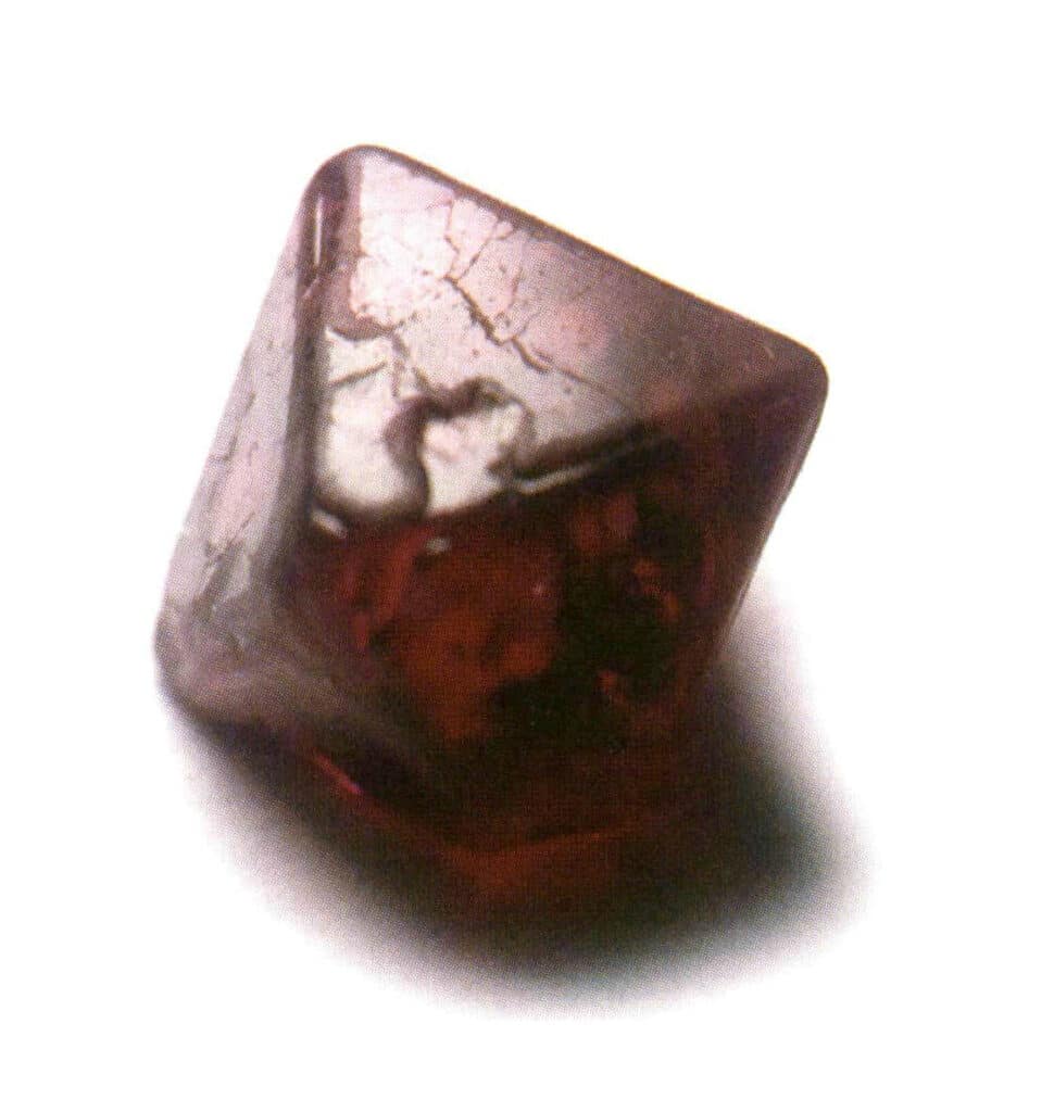
Figure 2-2-31 Common forms of spinel crystals
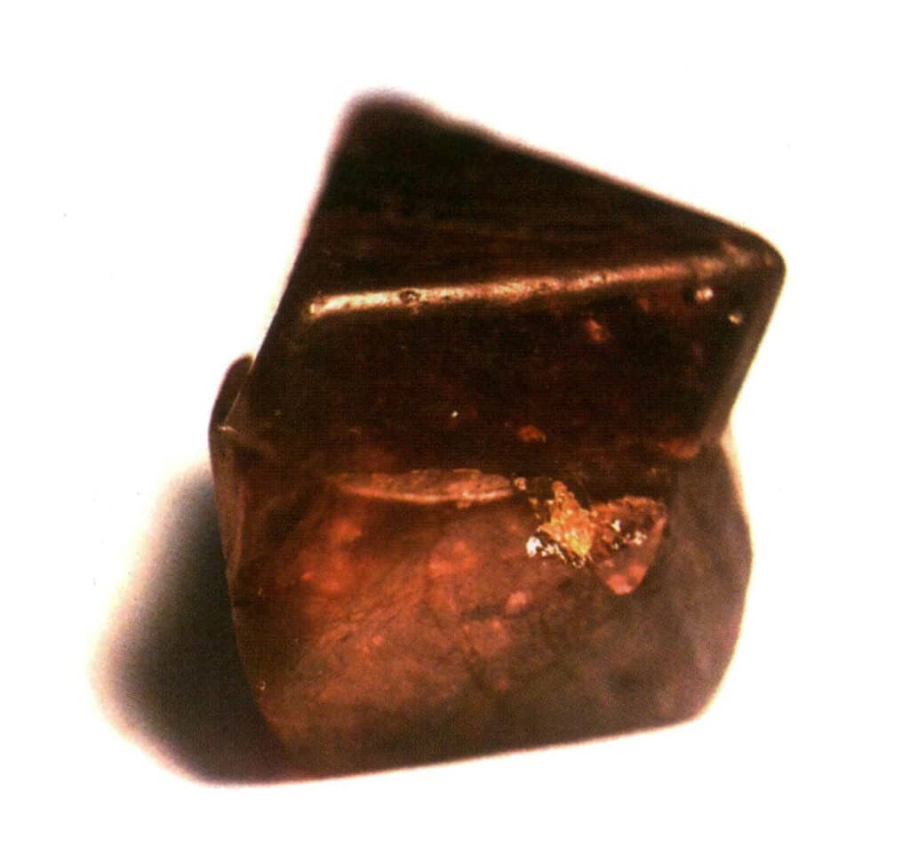
Figure 2-2-32 Contact twinning of spinel
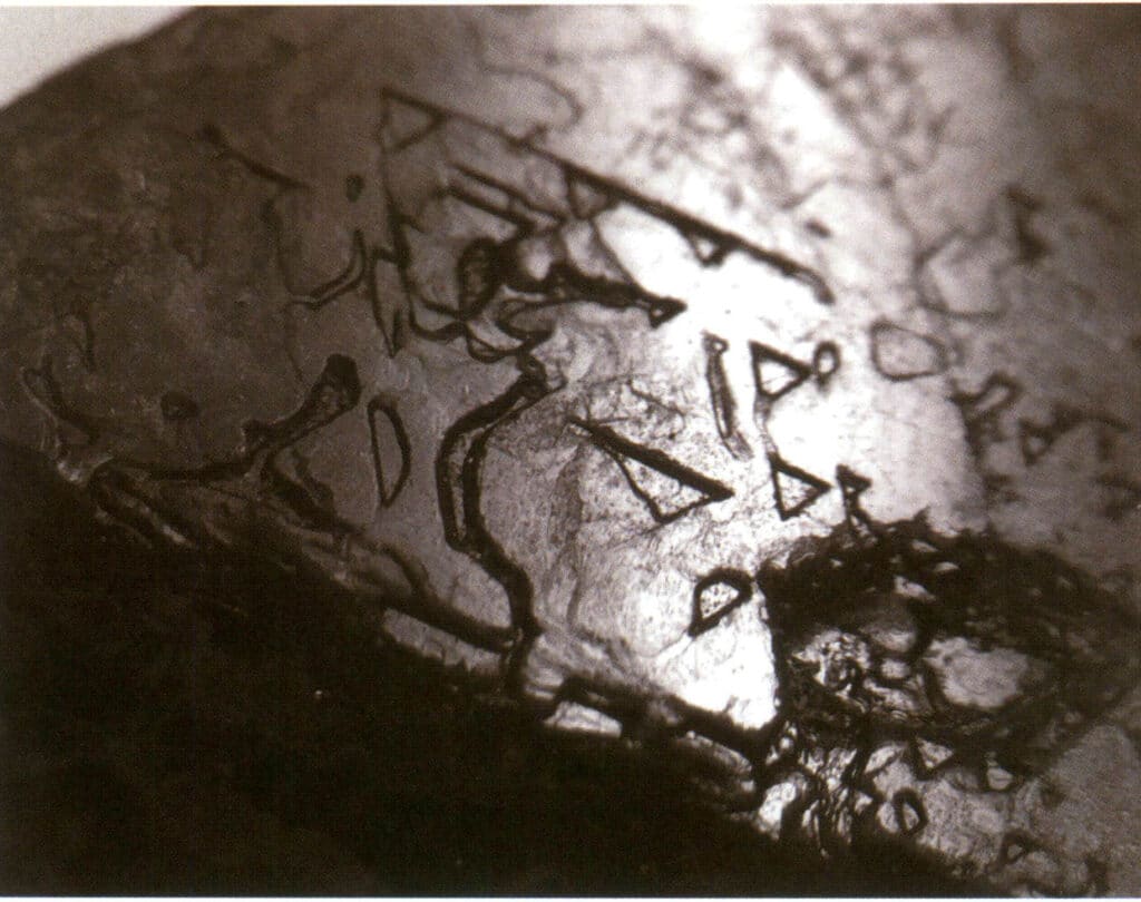
Figure 2-2-33 Inverted triangular etch figure pattern on the surface of spinel
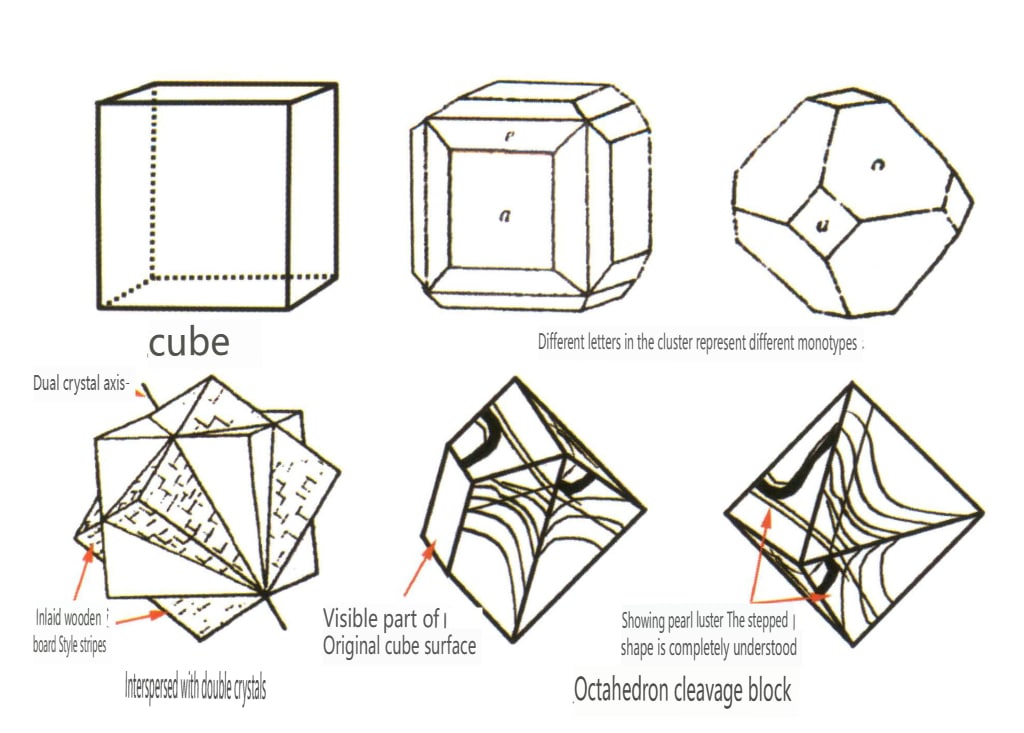
Figure 2-2-34 Fluorite crystal habits
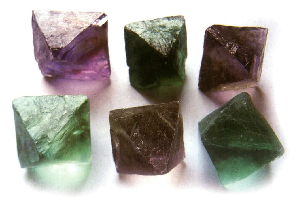
Figure 2-2-35 Fluorite Crystal
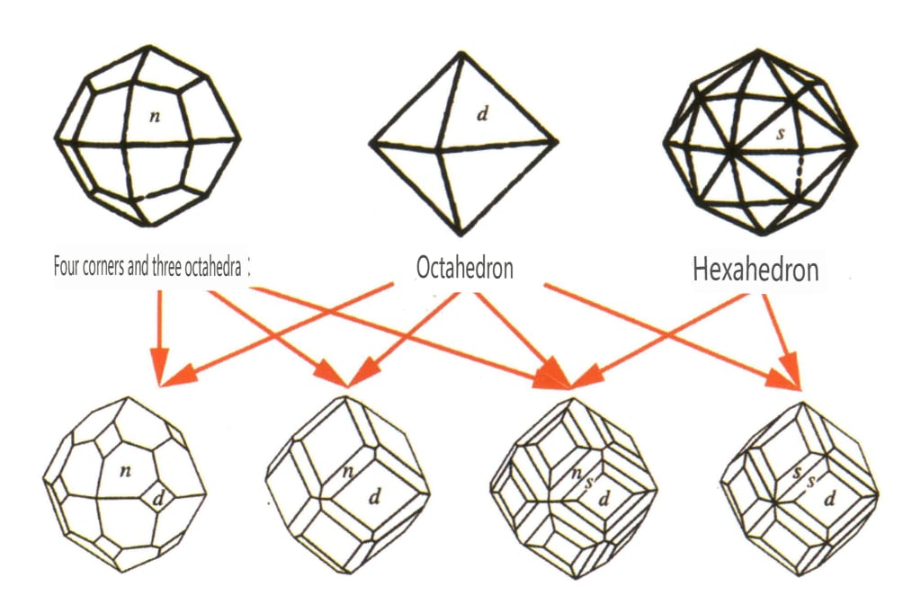
Figure 2-2-36 Garnet crystal habit
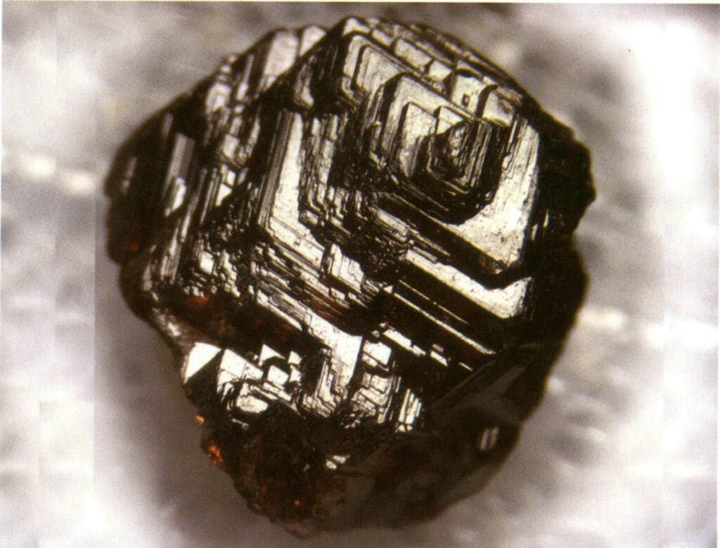
Figure 2-2-37 Concentric ring bands on the surface of garnet crystals that have the same shape as the crystal faces
Table 3: Common Gem Crystal Characteristics of Intermediate and Low Crystal Families
| Gems tone Name | Crystal Classification | Important Crystal Characteristics | |||
|---|---|---|---|---|---|
| Gems tone Name | Crystal Classification | Crystal Habit | Common crystal forms | Common twin forms | Common crystal face patterns |
| Beryl | Sześciokątny układ krystaliczny | Columnar crystal habit (Figure 2-2-38) | Hexagonal columnar crystal form (Figures 2-2-39, 2-2-40) | Rzadki | Visible longitudinal stripes |
| Lead stone | Tetragonalny układ krystaliczny | Columnar crystal habit (Figure 2-2-41) | A square column with a square cross-section, appearing together with a square double cone (Figure 2-2-42) | Visible knee-shaped twin crystals | No special patterns |
| Korund | Trigonal crystal system | Plate-like crystal habit, columnar crystal habit (Figure 2-2-43) | Rubies often present a hexagonal prism shape (Figure 2-2-44), while sapphires often exhibit a hexagonal bipyramidal barrel shaped crystal form (Figure 2-2-45) | Commonly seen bi-crystals. | Visible striations. |
| Tourmaline . | Columnar crystal habit (Figure 2-2-46) | The crystal faces at both ends are different, and the cross-section is a spherical triangle (Figure 2-2-47) | Rzadki | Visible longitudinal stripes (Figure 2-2-48) | |
| Quartz (crystal quartz) | Columnar crystal habit (Figure 2-2-49) | The cross-section is hexagonal, hexagonal bipyramids are rare (Figures 2-2-50, 2-2-51), hexagonal monopyramids are common | Common contact with bi-crystals (also known as Japanese bicrystals) | Common horizontal stripes on crystal surfaces | |
| Chryzoberyl | Trigonal crystal system | Columnar crystallization characteristics (Figure 2-¬2-52) | Monocrystalline is rare | Tri-crystalline is common (Figure 2-2-53), hexagonal and concave angles can be used as identification criteria | The stripes of tri-crystalline can be used as identification criteria |
| Topaz | Columnar crystal habit (Figure 2-2-54) | The cross-section is diamond-shaped, and the top often appears envelope-like (Figure2-2-55) | Bi-crystals are rare | Visible longitudinal stripes | |
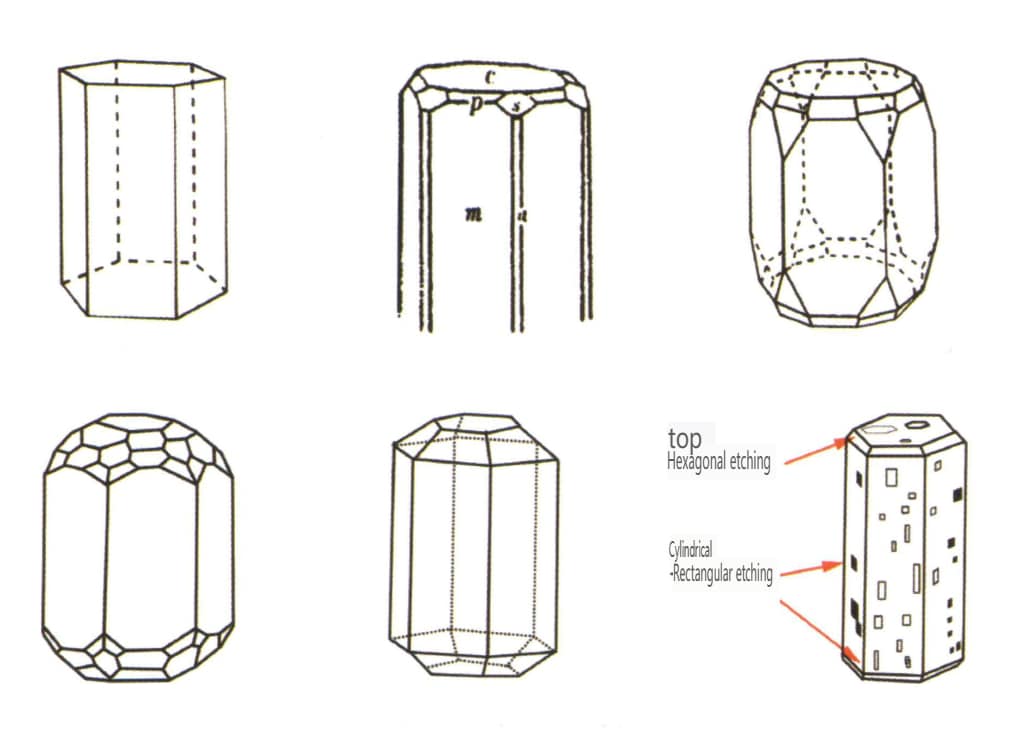
Figure 2-2-38 Beryl crystal habit
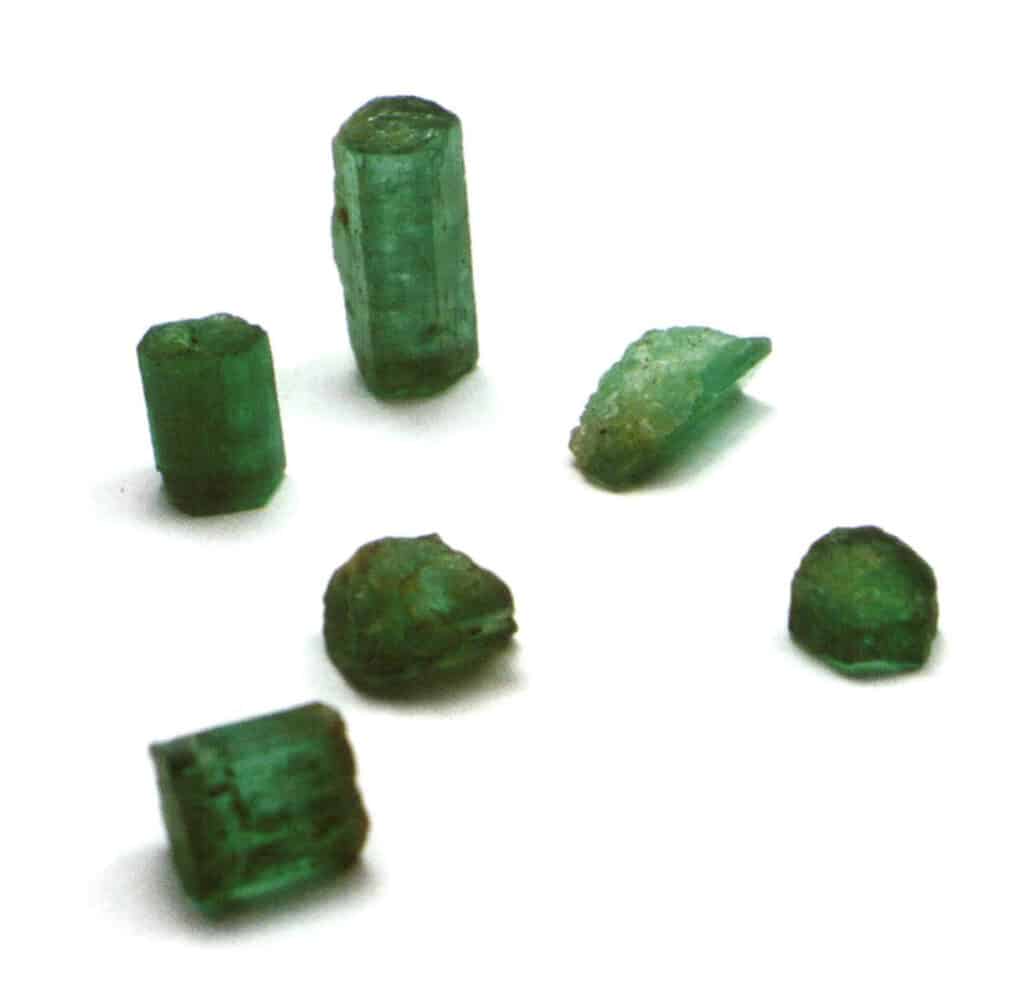
Figure 2-2-39 Common forms of emerald crystals
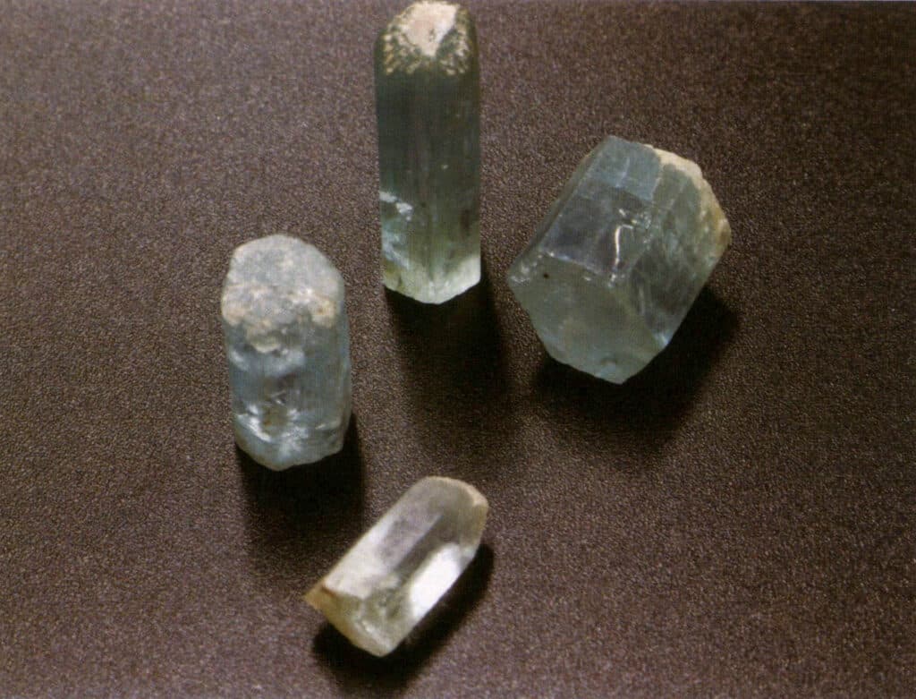
Figure 2-2-40 Common forms of aquamarine crystals
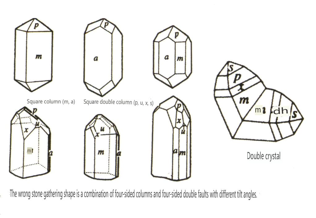
Figure 2-2-41 Zircon Crystal Habits
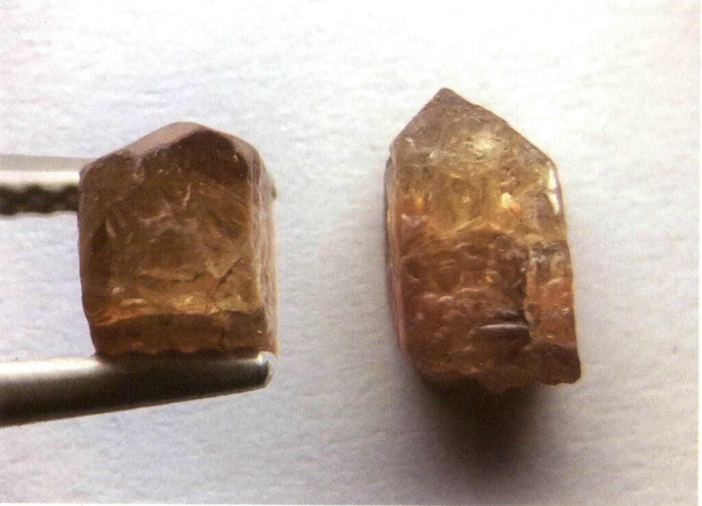
Figure 2-2-42 Zircon Crystal
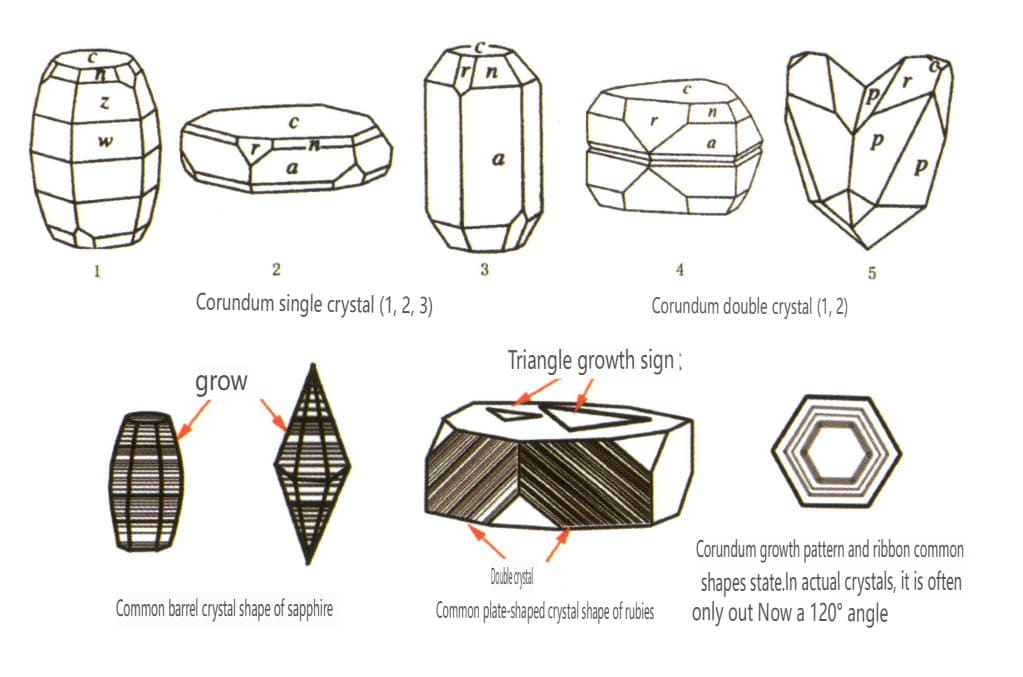
Figure 2-2-43 Corundum crystal habit
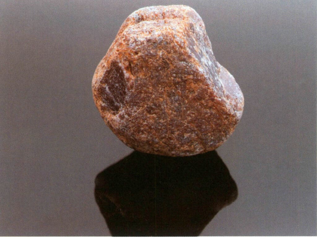
Figure 2-2-44 Ruby Crystal
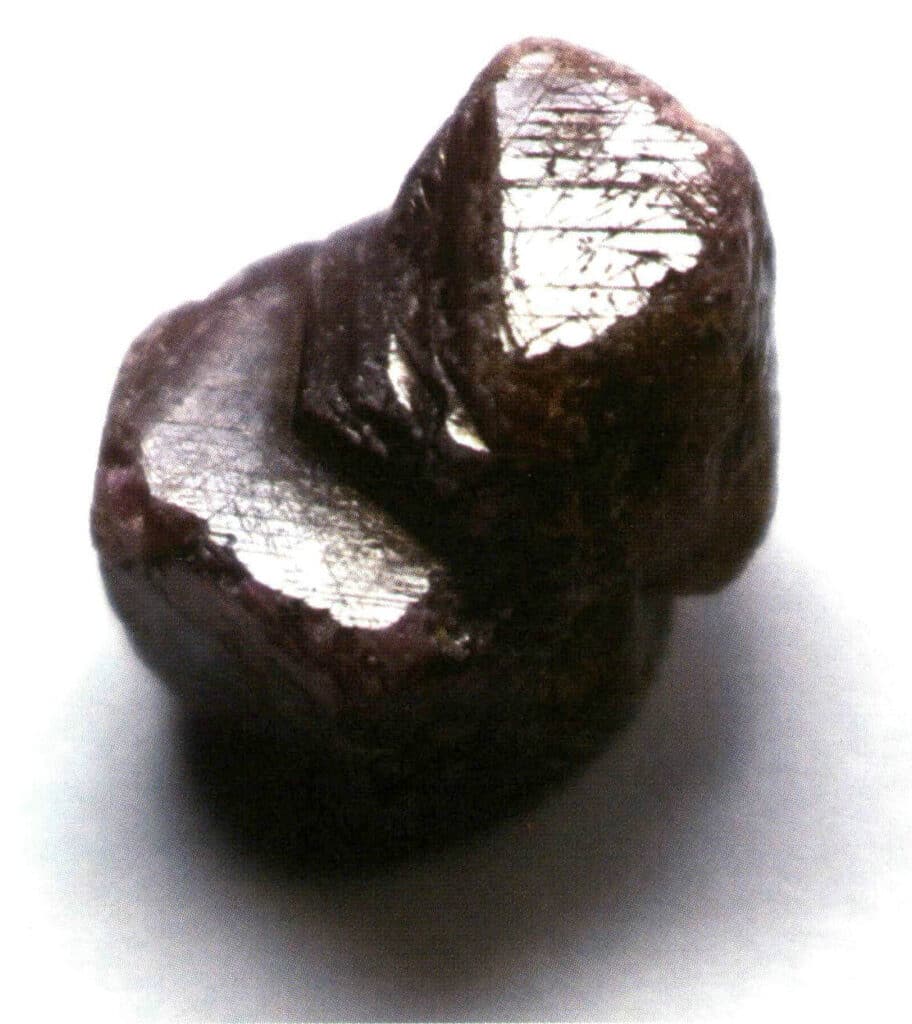
Figure 2-2-45 Mechanical twin of ruby
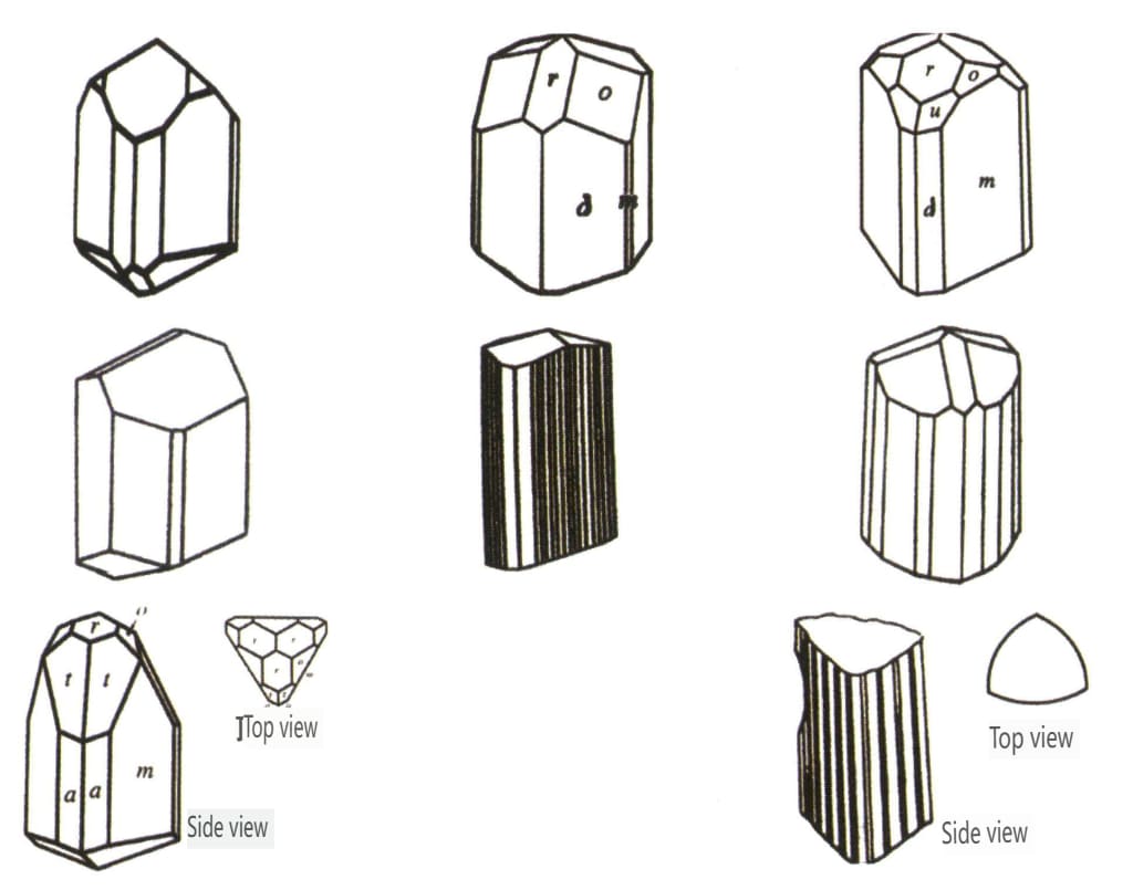
Figure 2-2-46 Tourmaline Crystal Habits
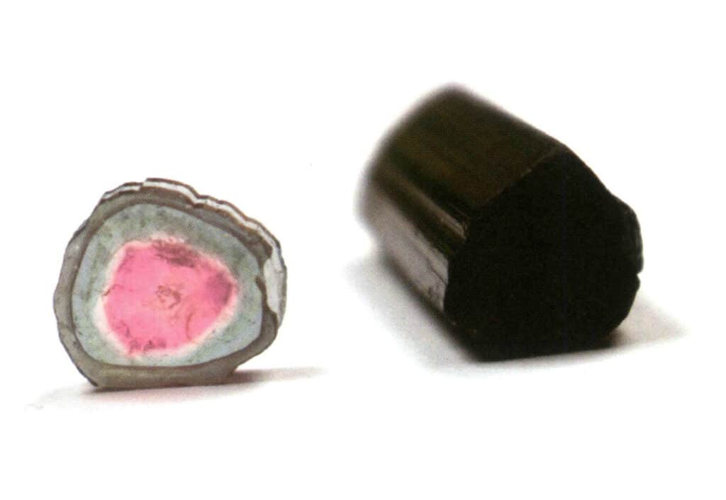
Figure 2-2-47 Tourmaline Crystal
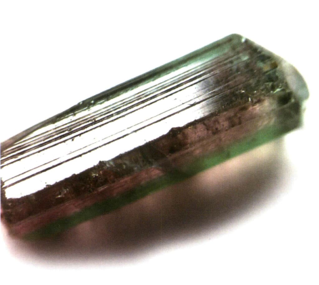
Figure 2-2-48 Surface Longitudinal Stripes of tourmaline Crystal
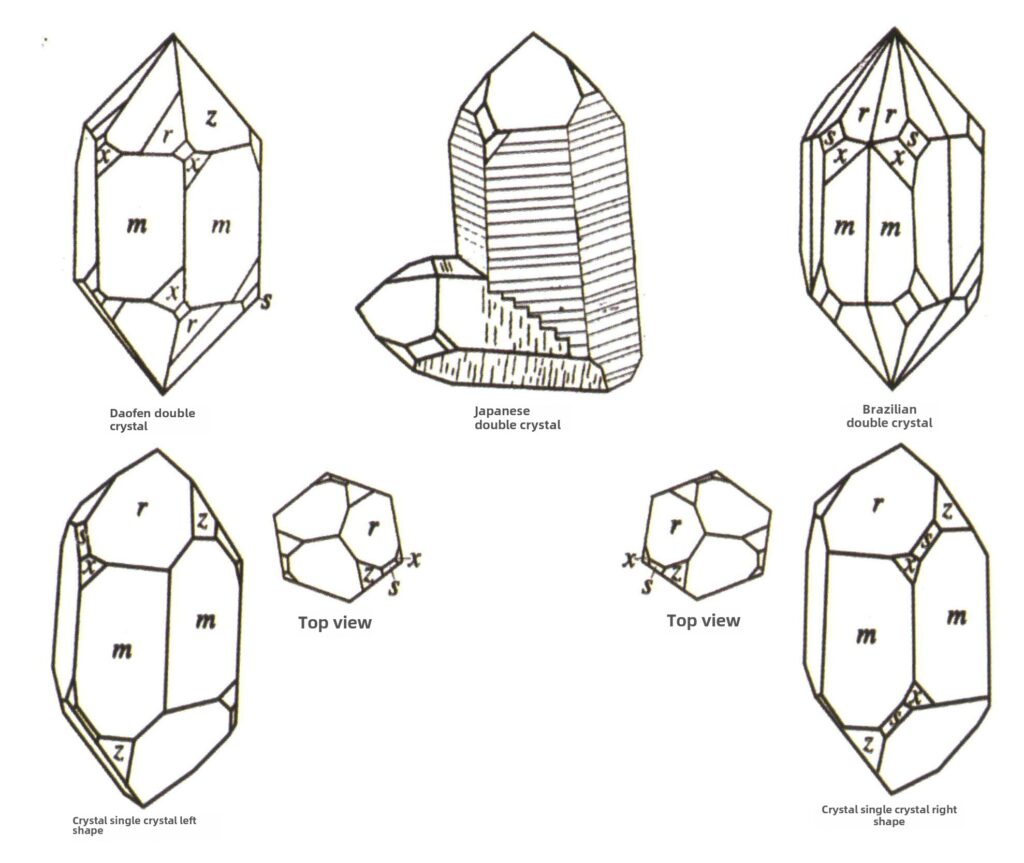
Figure 2-2-49 Crystal Crystallization Habits
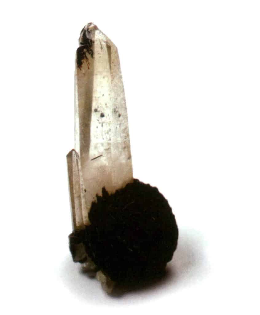
Figure 2-2-50 crystal body
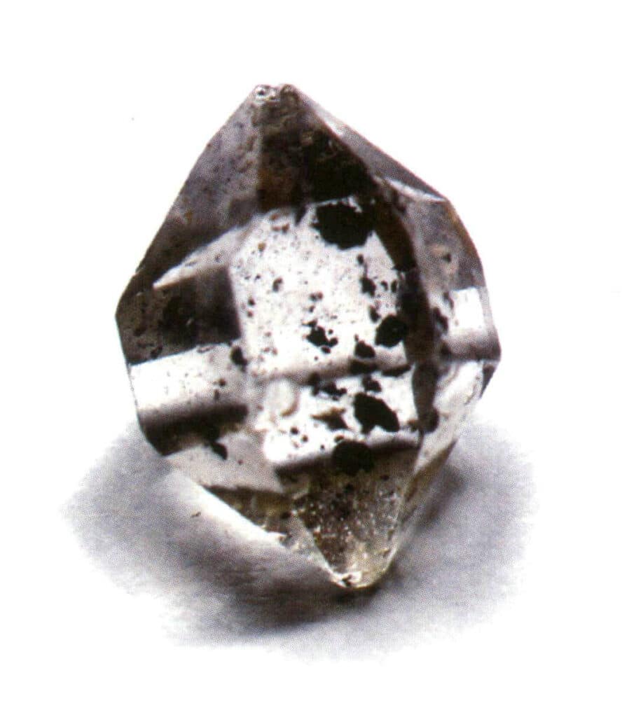
Figure 2-2-51 Crystal body
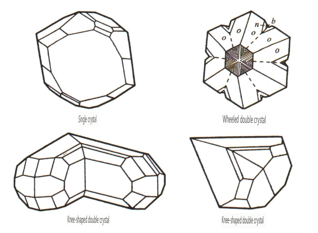
Figure 2-2-52 Crystal Habit of Chrysoberyl
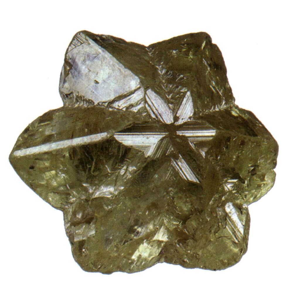
Figure 2-2-53 Crystal of Chrysoberyl
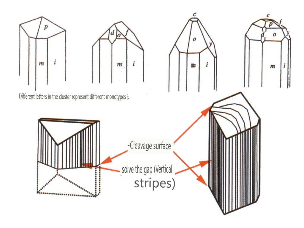
Figure 2-2-54 Crystal habits of topaz
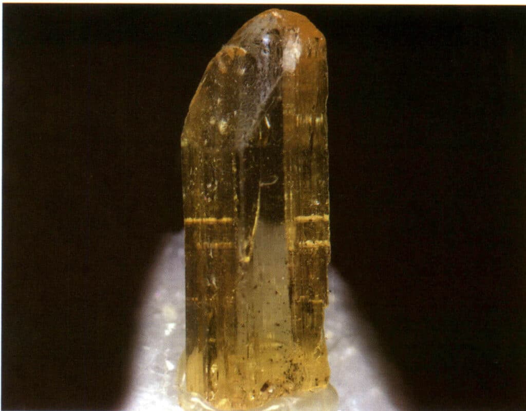
Figure 2-2-55 Topaz Crystal
Section IV Why do gemstone crystals grow differently
From a microscopic point of view, the gem crystal is a solid composed of elements of different sizes arranged by different rules. From a macroscopic point of view, many gems have crystal shape characteristics because of their different compositions. However, some special cases exist, such as heteromorphic. To better understand why gem crystals look different, here we will introduce five aspects: heteromorphic, isomorphism, molecular mechanical intermixing, water in gem minerals, and chemical composition of gemstones.
1. Heteromorphic
Although some minerals have the same chemical composition, they have very different crystal structures (the arrangement of elements in three-dimensional space) and exhibit significant differences in physical and chemical properties (Table 4). We refer to this phenomenon as heteromorphism, for example, diamond and graphite (Figure 2-2-56).
Common quartz has the phenomenon of heteromorphism. Sillimanite, andalusite, and kyanite are a group of heteromorphism variants.
The transformation of heteromorphism occurs under solid-state conditions. During the structural transformation process, pressure can develop within the crystal, often leading to the formation of twinning inside the crystal.
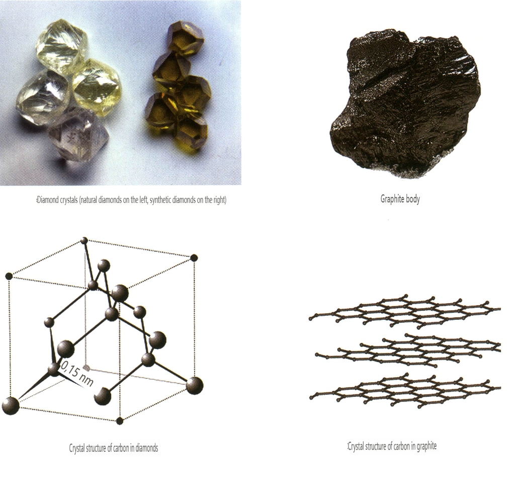
Table 4: Comparison of Properties of Diamond and Graphite
| Mineral | Diament | Graphite |
|---|---|---|
| Komponenty | Carbon (C) | Carbon (C) |
| Formation Conditions | Wysoka temperatura i wysokie ciśnienie | High temperature |
| Crystal system, habit | Isometric crystal system, octahedron, rhombic dodecahedron | Hexagonal crystal system, layered |
| Kolor | Colorless, yellow, blue, pink, green, etc. | Czarny |
| Połysk | Adamantine luster | Metallic Luster |
| Przejrzystość | Transparent to opaque | Opaque |
| Współczynnik załamania światła | 2.40 ~ 2.48 | 1.93 ~ -2.07 |
| Mechanical Properties | Moderate octahedral cleavage, hardness 10, density 3.52 | A set of perfect cleavage, hardness 1, density 2.10 |
| Other properties | Excellent thermal conductivity; except for natural blue diamonds which are semiconductors, diamonds of other colors are insulators. | Moderate thermal conductivity, good electrical conductivity |
2. Isomorphism
Isomorphism refers to the phenomenon where some particles in the lattice structure are replaced by other particles with similar properties, resulting in slight changes in lattice parameter and physical and chemical properties. In contrast, the crystal structure remains fundamentally unchanged. It can be understood as the elements in the gemstone crystal being replaced by other elements. In contrast, the repeating pattern of the gemstone crystal elements remains the same, with slight deviations in the distances between atoms. Still, the physical-chemical properties of the gemstone crystal undergo slight changes (Figure 2-2-57 to Figure 2-2-58).
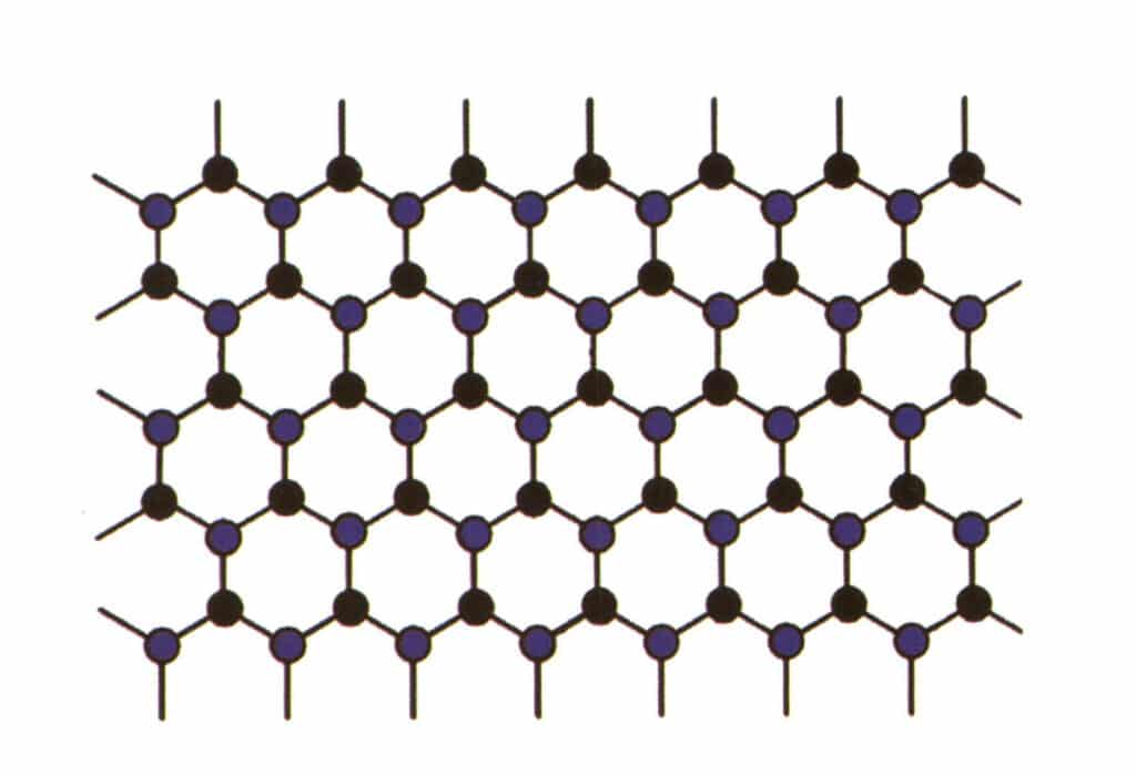
Figure 2-2-57 Crystal structure simulation diagram (blue and black indicate element particles)
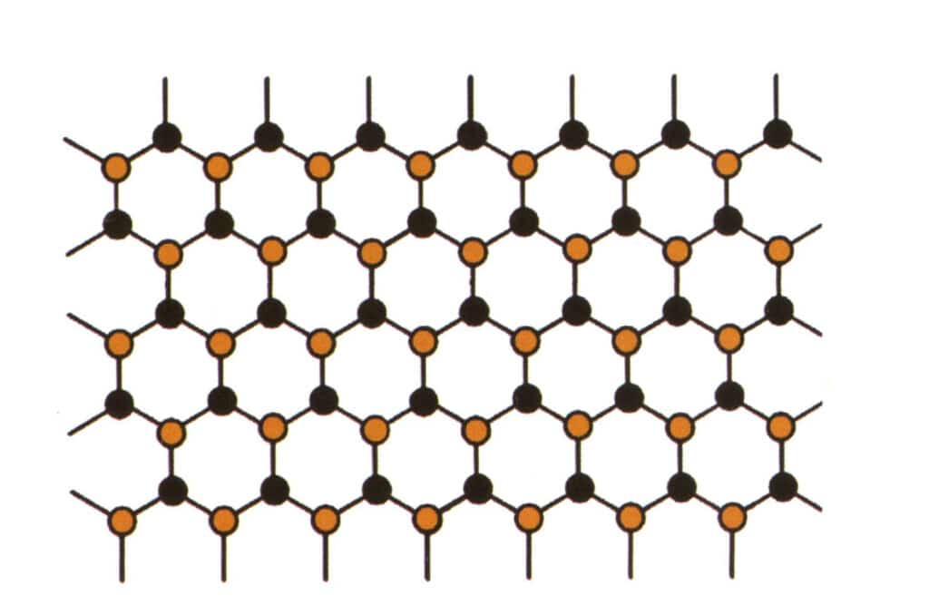
Figure 2-2-58 Crystal structure simulation diagram (black represents elemental particles, yellow represents new elemental particles that partially substitute the blue elemental particles, yellow may not completely replace all blue particles)
The concept of isomorphism can explain why gemstones from the same family can have so many colors and why there are variations in refractive index and density among gemstones of the same family.
A family can be understood as a type of gemstone where the repeating patterns of crystal elements are the same, but the physical and chemical forms are slightly different. For example, the corundum family includes two members, ruby and sapphire, while the beryl family includes emerald, aquamarine, and morganite varieties.
(1) Olivine
The chemical composition of olivine is (Mg,Fe)₂SiO₄. The complete isomorphic substitution of Fe and Mg elements occurs in its composition. As the Fe content in olivine increases, the color of olivine becomes darker, the refractive index increases, and the density also increases.
(2) Corundum
Pure corundum without any impurities (Al₂O₃) is colorless, and when Cr replaces Al, the gem presents a rose-red to red hue, known as ruby. The remaining colors are called sapphire, such as orange-yellow sapphire or colorless sapphire. The commonly referred to sapphire is specifically the blue sapphire, where Fe and Ti replace Al. The higher the content of the coloring elements in the substitute gem, the deeper the color of the gem; conversely, the lower the content, the lighter the color.
(3) Tourmaline
Tourmaline refers to the same type of gem as tourmaline, where tourmaline is its mineralogical name, and tourmaline is its gemological name. The chemical composition of beryl is (Na, Ca)R₃Al₃Si₆O₁₈(O, OH, F), where R is mainly Mg , Fe , Cr , Li, Al , Mn, and the elements in R can completely or partially substitute each other, resulting in an extremely wide variety of colors for tourmaline. For example, when R is mainly Fe, beryl presents a deep blue or even black color; when R is mainly Mg, beryl presents yellow to brown; when R is mainly Li or Mn, beryl presents rose or light blue; when R is mainly Cr, tourmaline presents a deep green.
From the above, it can be seen that substituting elements with similar properties leads to more beautiful and brilliant colors in gems.
3. Molecular Mechanical Intermixing
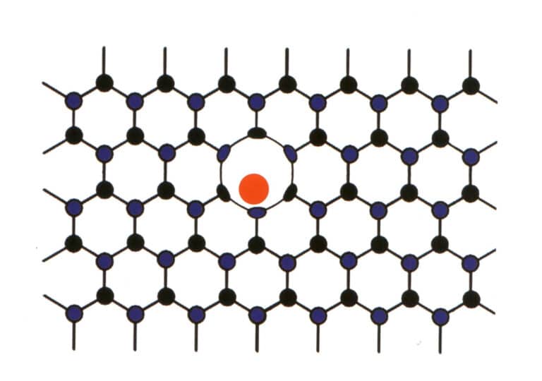
Sometimes, certain elements forcibly enter between the main elements of regularly arranged gemstones. However, the low proportion of the entering elements does not disrupt the repetitive pattern of the main gemstone elements, only causing deformation (Figure 2-2-59). This situation is referred to as molecular mechanical intermixing, such as the molecular mechanical intermixing of nitrogen and boron in diamonds, which produces blue, pink, and yellow diamonds, which are highly valuable.
4. Water in Gem Minerals
Some gemstones contain water, which is an important component of gem minerals and is closely related to the properties of the gemstones. Based on the form of water present in gem minerals and its role in the crystal structure, the water in gemstones can be divided into two categories: one is absorption water, which is unrelated to the crystal structure, and the other is water that participates in the mineral crystal structure, including crystallization water, zeolitic water, interlayer water, and constitution water. The water closely related to gemstones includes absorption water, crystallization water, and constitution water.
One is to absorption water, such as Opal (chemical composition is SiO₂ • nH₂O, n represents the number of H₂O, the content is variable) in the water molecule, which is a neutral water molecule mechanically adsorbed for mineral particles or fracture surfaces. When the temperature reaches 100 ~ 110°degrees under normal pressure, the water molecules can all escape and do not damage the crystal lattice structure, so to avoid the Opal in the counter in a long time of strong light exposure dry crack, should put a cup of water in the counter.
Second is the crystallization water, such as the water of crystallization in turquoise [chemical composition is CuAl₆(PO₄)₄(OH)₈•4H₂O, where the content of H₂O can reach 19.47% ]. This neutral water molecule exists in fixed positions within the lattice and serves as a structural unit, being part of the mineral’s chemical composition. The temperature at which water of crystallization escapes generally does not exceed 600℃ and usually escapes at 100 -200℃. When a gemstone loses its water of crystallization, its crystal structure is damaged, forming a new structure.
Third is constitution water, also known as combined water, which participates in the mineral lattice in the form of OH⁻, H⁺, H₃O⁺ plasma, with OH⁻ being the most common. Constitution water is part of the mineral’s chemical composition, occupying fixed positions in the lattice structure with a defined proportion in its composition. Structural water requires a higher temperature to escape and damage its structure, usually around 600 -1000℃. When a gemstone loses structural water, its crystal structure is destroyed. Many gemstones contain constitution water, such as tourmaline[chemical composition is ( Na, Ca )R₃Al₃Si₆O₁₈(O, OH, F), where R mainly includes Mg , Fe , Cr, Li, Al, Mn, etc., and the elements in R can completely or partially substitute each other], and topaz [chemical composition is Al₂SiO₄( F, OH) ₂ ].
5. The chemical composition of gemstones
Gems, like other substances, are composed of chemical elements. Each type of gem has its specific chemical composition and a certain range of variation, which determines the various characteristics and properties of the gem. Gems belong to minerals and rocks, and the classification of a gem’s chemical composition can be traced back to the chemical composition of minerals.
Currently, the main classification methods for minerals include classification by chemical composition (Dana system), geochemical classification, genetic classification, application classification, and crystal-chemical classification. The widely adopted method is the chemical classification based on chemical composition and crystal structure (Hugo Strunz system) (Table 5).
Table 5: Mineral Crystal Chemical Classification System
| Level sequence | Basis for Division | Example |
|---|---|---|
| Major Category | Compound type | Oxygen-containing Salt Major Category |
| Class | Anion or Complex Anion Types | Silicate class |
| (Subcategory) | Anionic complex structure | Framework silicate subclass |
| Grupa | Crystal structure types and ionic properties | Corundum group, beryl group, garnet group |
| (Subgroup) | Cation types | Alkaline feldspar subgroup |
| Specie | Certain crystal structure and chemical composition | Orthoclase KAlSi3O8 |
| (Subspecies) | Same crystal structure, different composition or properties, morphology | Adularia KAlSi3O8 |


