What Makes Low Melting Point Alloy Jewelry Unique: A Guide to Production and Care
Discover the Art of Crafting: Inside the World of Low Melting Point Alloy Jewelry
Low melting point or fusible alloys are binary, ternary, or quaternary alloys composed of metal elements such as lead, tin, bismuth, and cadmium. Their characteristics include a bluish-gray or silver-white cold color tone, low melting point, easy melting, simple casting, soft alloy quality, and ease of carving, making them widely used for creating intricately designed craft ornaments.
Due to their relatively low melting point, zinc alloys are also introduced with fusible alloys. Zinc alloy jewelry is another important type of popular jewelry material made from low-melting-point alloys, with the main types of zinc alloys used for jewelry being zinc-aluminum alloys, zinc-aluminum-magnesium alloys, and zinc-aluminum-copper alloys.
Sinkkiseos rintaneula
Sisällysluettelo
Section I Low Melting Point Alloy Accessories
1. Introduction to Several Typical Low Melting Point Metal Elements
(1) Tin
Tin is the fourth rare metal, following platinum, gold, and silver. Its chemical symbol is Sn, and its atomic number is 50, atomic weight is 119, density is 7.31g/cm3, and melting point is 232℃. Tin is a silvery-white, ductile metal with a low coefficient of friction, very soft, and has good plasticity and ductility. The elongation rate of cast tin at 17℃ is 45%-60%, tensile strength is 25-40MPa, and yield strength is 12-25MPa. Tin is oxidized quickly in air by oxygen, water, and carbon dioxide, forming a protective film on its surface. Due to its non-tarnishing, non-oxidizing, and non-toxic characteristics, tin is very suitable for contact with the human body. Given the high cost of gold and the tendency of silver to tarnish, tin-crafted jewelry has many advantages. It is recognized as one of the excellent materials for jewelry outside of gold and silver, showcasing both a high-end appearance and good metallic properties.
In commercial pure tin, the total impurity content does not exceed 0.25%, and in the ASTMB-339 standard, the minimum tin content required for grade A tin ingots is 99.8%. Tin has poor cutting performance and tends to stick to tools, so tin products are not suitable for mechanical processing and shaping but are suitable for pressure forming and casting.
China has abundant tin resources, with proven reserves of over 3 million tons, accounting for about a third of the world’s total reserves.
(2) Lead
Lead is one of the earliest metals used by humans, with the chemical symbol Pb, atomic weight of 207, and atomic number of 82, and has the highest atomic number among all stable chemical elements. The density is 11.33g/cm3, and the melting point is 327℃. Lead is a blue-tinted silvery-white heavy metal, soft, low tensile strength, and a ductile main group metal. Lead has four stable isotopes in nature: lead-204, lead-206, lead-207, and lead-208, as well as more than 20 radioactive isotopes. Metallic lead is quickly oxidized in air by oxygen, water, and carbon dioxide, forming a protective film on its surface; when heated, lead can quickly react with oxygen, sulfur, and halogens; lead is almost inert with cold hydrochloric acid and cold sulfuric acid, but can react with hot or concentrated hydrochloric acid and sulfuric acid; lead reacts with dilute nitric acid but does not react with concentrated nitric acid; lead can slowly dissolve in strongly alkaline solutions. Lead, and its compounds are highly toxic to the human body and can accumulate in the body.
(3) Antimony
Antimony is a brittle, lustrous silver-white solid with the chemical symbol Sb, atomic number 51, atomic weight 121.76, melting point of 631℃, and density of 6.65g/cm3. Antimony was discovered in ancient times, with the content of 1×10⁻⁶ in the Earth’s crust, and its abundance in the Earth’s crust mainly exists in the form of the element itself or stibnite and valentinite. Antimony has two allotropes: the yellow variant is stable only at -90℃; the metallic variant is the stable form of antimony. Antimony reacts with water to release hydrogen gas only when red-hot; at high temperatures, it can react with oxygen to form antimony trioxide, which is an amphoteric oxide, poorly soluble in water but soluble in acids and bases; it can react with concentrated nitric acid.
(4) Bismuth
Bismuth is a silvery-white metal that is brittle and easily crushed, with the chemical symbol Bi, atomic number 83, atomic weight 209, melting point of 271℃, and density of 9.81g/cm3. Bismuth content in the Earth’s crust is 20×10-6, and mainly exists in nature as elements or compounds, with two allotropes but only one stable isotope. It reacts with air when red-hot; bismuth can directly react with sulfur and halogens; it is insoluble in non-oxidizing acids but soluble in nitric acid and hot concentrated sulfuric acid. A typical characteristic of bismuth is that its volume increases when it transitions from liquid to solid, meaning it expands upon solidification.
(5) Cadmium
Cadmium is a shiny, soft metal that is silver-white or lead-gray in color, has ductility, the chemical element symbol is Cd, the atomic number is 48, the atomic weight is 112, and the density is 8.64 g/cm3, melting point is 321℃. Cadmium has 8 natural stable isotopes and 11 unstable artificial radioactive isotopes. It quickly loses its luster in the air and is covered with a layer of oxide film, which prevents further oxidation. It is insoluble in water and soluble in most acids.
(6) Zinc
Zinc is a bluish-white metal with a density of 7.14g/cm3 and melting point of 419.5℃. It is relatively brittle at 100-150℃, softens, and becomes brittle again after exceeding 200℃.
Zinc has active chemical properties. In the air at room temperature, a thin and dense layer of basic zinc carbonate film forms on the surface, which prevents further oxidation. Due to the easy formation of a protective film on the surface of zinc at room temperature, its largest use is in the galvanizing industry. When the temperature reaches 225℃, zinc oxidizes vigorously. When burned, it emits a blue-green color flame. Zinc is easily soluble in acid and can easily displace gold, silver, copper, etc., from the solution.
Zinc has strong reducing properties and can release flammable hydrogen gas when in contact with water, acids, or alkali metal hydroxides. Reactions with oxidizers or sulfur can cause combustion or explosions. Zinc powder can form explosive mixtures with air, which can be easily ignited by an open flame, leading to explosions, and damp dust can easily self-heat and ignite in the air.
The above several typical low melting point alloy elements are shown in Table 4-1.
Table 4-1 Several Typical Low Melting Point Alloy Elements
| Element name | Element symbol | Järjestysluku | Atomic weight | Density /g • cm-3 | Melting point/℃ |
|---|---|---|---|---|---|
| Antimony | Sb | 51 | 121. 76 | 6.65 | 631 |
| Bismuth | Bi | 83 | 209 | 9.81 | 271 |
| Cadmium | Cd | 48 | 112 | 8.64 | 321 |
| Lead | Pb | 82 | 207 | 11. 33 | 327 |
| Tin | Sn | 50 | 119 | 7.31 | 232 |
| Zinc | Zn | 30 | 65 | 7. 14 | 419. 5 |
2. Typical Low Melting Point Alloys
2.1 Tin Alloy
Tin has three allotropes: white tin, gray tin, and brittle tin. The most common is white tin, which is silver-white, but below 13℃, it transforms into powdery gray tin, a phenomenon known as “tin pest.” To avoid this situation, alloying elements such as antimony, bismuth, lead, and cadmium can be added to tin to prevent the occurrence of “tin pests.” Additionally, adding alloying elements can improve tin’s mechanical properties and casting performance.
(1) The Effect of Alloying Elements on the Properties of Tin Alloys
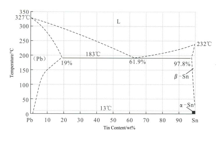
① Lead. Tin and lead form a typical binary eutectic alloy, as shown in the phase diagram in Figure 4-1, with a eutectic temperature of 183℃ and a eutectic point of 38.1℃Pb. It lowers the melting point, improves the casting performance of tin alloys, has good fluidity, reduces porosity, refines grains, and decreases the specific heat capacity and thermal conductivity of tin alloys. Lead increases the tin’s hardness while the alloy’s ductility remains intact. Lead is a toxic element, and high lead content can affect the luster of the alloy’s surface.
② Antimony. Antimony increases the strength and hardness of tin alloys, reduces ductility, expands during solidification, aids in surface replication, and helps create sharp and clear letters. However, it also brings the issue of surface plating discoloration. The solid solubility of antimony in tin reaches a maximum of 10.4% at 246°C. The solid solubility of antimony at room temperature is about 2%. An antimony content of 20% or less when the alloy has ductility can be processed but does not lose its beautiful luster. Therefore, adding an appropriate amount of tin to the alloy can achieve a certain hardness, making it workable without losing shape.
③ Bismuth. It is a brittle metal, pale red, with a high luster, and expands upon solidification, which is more pronounced than other metals. Bismuth helps reduce the solidification shrinkage of alloys and improves surface replication performance. However, bismuth can increase the brittleness of alloys, and its content should be controlled.
④ Copper. Copper increases the hardness of alloys and enhances tensile strength, which is commonly used in tin-lead-antimony alloys.
⑤ Cadmium. Cadmium is a bluish-white, soft, ductile metal that is toxic. Cadmium lowers the melting point of alloys, allowing them to be cast at lower temperatures, and it also improves ductility and reduces solidification shrinkage, which is beneficial for casting large, flat pieces.
(2) Tin Alloy Categories
The main categories of tin alloys used for craft jewelry are as follows.
① White wax. Also known as “white tin,” it is a common term for tin-lead alloys, with a long history of use since Roman times in utensils and other daily necessities, such as tin tables, goblets, plates, candlesticks, or clothing. Traditional white wax has a high lead content, is toxic, and affects surface gloss. Contemporary white wax is a high-tin alloy containing approximately 6% antimony and 1%-2% copper. The antimony content is usually limited to below 4% for white wax intended for drawing, but cast white wax can contain up to 8% antimony and 2% copper. Small amounts of bismuth or silver can also be added if necessary to improve the hardening properties of white wax.
Currently, there is a specific standard for pewter in Europe, EN611-1996, which also includes the solder standard (EN29453) used to join fittings with pewter products. The International Tin Research Institute has published a guide to pewter products worldwide. Depending on the alloy composition, the melting point of pewter is 240-295℃, and these alloys can be cast using various techniques, including gravity die casting and centrifugal casting. Although pewter products have traditionally been cast, modern manufacturing techniques have utilized tin’s excellent stamping, stretching, and spinning properties to produce from rolled sheets. Contemporary pewter product manufacturers have begun to shift from traditional items like goblets, tea caddies, and coffee pots to meet the needs of modern life, and there are now pewter cigarette lighters, ashtrays, lamps, and clocks.
② Tin-based die-casting alloys. Tin-based alloys are preferred for die casting because their low melting point and unique fluidity help produce strong castings with complex structures or shapes without special requirements or damage to the molds. Generally, for most applications, tin-based die-casting alloys have good corrosion resistance and can be electroplated if needed.
③ Tin-based low-melting alloys. Bismuth, tin, lead, cadmium, and indium are all low-melting-point metals. When these metals are combined in different proportions (binary, ternary, or quaternary alloys), alloys with even lower melting points can be obtained, commonly called “low-melting alloys.” In addition, these alloys have some valuable properties, including low vapor pressure, good thermal conductivity, ease of processing, high fluidity suitable for casting molds, controllable dimensions during solidification, fine detail reproduction in casting, and reusability.
2.2 Lead Alloy
Lead alloy is an alloy composed of lead as the base and other elements. The surface of lead alloy generates oxides, sulfides, or other complex salts during the corrosion process, which helps to prevent oxidation, sulfuration, dissolution, or volatilization, thus providing good corrosion resistance in air, sulfuric acid, fresh water, and seawater. If lead alloys contain impurities such as bismuth, magnesium, or zinc that are not soluble in the lead or form a second phase, their corrosion resistance will decrease; adding tellurium and selenium can eliminate the harmful effects of bismuth on corrosion resistance. Adding antimony and tellurium to lead alloys containing bismuth can refine the grain structure, increase strength, suppress the harmful effects of bismuth, and improve corrosion resistance.
Lead alloys have low deformation resistance, and cast ingots can be processed into sheets, strips, pipes, bars, and wires using processes such as rolling and extrusion without heating or intermediate annealing. The tensile strength of lead alloys is 0.3-0.7MPa, much lower than that of most other metal alloys. Antimony is an important element that strengthens the matrix; it is only partially soluble in lead and can be used for solid solution and aging strengthening. However, if the content is too high, the toughness and corrosion resistance of the lead alloy can deteriorate.
Lead, tin, and antimony can form eutectic alloys. The lead alloys used for craft ornaments generally take the ternary Pb-Sn-Sb alloy near the eutectic point, which has good fluidity, almost no solidification shrinkage, and a beautiful casting surface.
2.3 Selection of Low Melting Point Alloy Materials for Jewelry
Table 4-2 Domestic Low Melting Point Alloy Craft Jewelry Materials
| Product name | Malli | Product Name Element content Composition/% | Melting point/ ℃ | Main application | |||
|---|---|---|---|---|---|---|---|
| Tin | Muut | Antimony | Lead | ||||
| Babbitt alloy | 0 # A | 96 | 2 | 2 | Ei ole | 200 | Light weight, moderate hardness, good toughness, low temperature crystallization, lead-free and non-toxic suitable for the production of high-grade jewelry, cooking utensils, drinking utensils and glossy large variety of high-grade handicrafts. |
| 0 # B | 92 | 2 | 6 | Ei ole | 200 | Light weight, strong hardness, good densification, low-temperature crystallization, lead-free and non-toxic applicable to the production of high-grade jewelry, cooking utensils, drinking utensils and glossy large variety of high-grade handicrafts. | |
| 0 # C | 88 | 4 | 8 | Ei ole | 200 | Light weight, strong hardness, good densification, low temperature crystallization, lead-free and non-toxic. Suitable for making high-grade jewelry, cooking utensils, drinking utensils and various high-grade crafts with large glossy surface (such as wind chimes). | |
| No.1 lead-tin alloy | 1 # A | 92 | 3 | 2 | Residual | 200 | It is suitable for the production of high-grade jewelry and handicrafts with strong toughness, low density and large glossy surface. |
| 1 # B | 90 | 4 | 3 | Residual | 215 | ||
| 1 # C | 85 | 5 | 4 | Residual | 220 | ||
| No.2 lead-tin alloy | 2 # A | 72 | 5 | 3 | Residual | 230 | Suitable for making various kinds of high-grade jewelry and handicrafts with strong toughness, small density and narrow glossy surface. |
| 2 # B | 63 | 5 | 4 | Residual | 230 | Suitable for the production of mid-range jewelry and handicrafts with better toughness, lower density, narrower polished surface or larger polished surface without polishing. | |
| 2 # C | 50 | 4 | 4 | Residual | 250 | ||
| No.3 lead-tin alloy | 3 # A | 35 | 4 | 4 | Residual | 270 | Suitable for the production of a variety of mid-range jewelry and handicrafts with better toughness, lower density and larger polishing surface. |
| 3 # B | 30 | 3 | 3 | Residual | 270 | ||
| 3 # C | 25 | 1 | 2.8 | Residual | 270 | ||
| No.4 lead-tin alloy | 4 # A | 15 | 1 | 3 | Residual | 280 | Suitable for making various kinds of mid-range jewelry or handicrafts with better toughness, lower density, narrower polishing surface or without polishing. |
| 4 # B | 12 | 1 | 3 | Residual | 280 | ||
| 4 # C | 10 | 1 | 3 | Residual | 280 | ||
| No.5 lead-tin alloy | 5 # A | 8 | 2 | 3 | Residual | 286 | It is suitable for making all kinds of mid-range jewelry or handicrafts with better toughness, less density, narrower polishing surface or without polishing. |
| 5 # B | 6 | 2 | 3 | Residual | 290 | ||
| No.6 lead-tin alloy | 6 # A | 5 | 1 | 3.5 | Residual | 300 | Suitable for making all kinds of general jewelry and heavy crafts. |
| 6 # B | 3 | 1 | 3.5 | Residual | 300 | ||
| 6 # C | 2 | 1 | 3 | Residual | 320 | ||
| (Tan Derui and Chen Guanyi, 1996) | |||||||
Table 4-3 Foreign Tin Alloy Craft Jewelry Materials
| Serial number | Sn | Sb | Cu | Impurities | Remarks | ||||
|---|---|---|---|---|---|---|---|---|---|
| Pb | Kuten | Fe | Zn | Cd | |||||
| 1 | 91 ~ 93 | 6 ~ 8 | 0. 25 ~ 2 | 0.05 | 0.05 | 0.015 | 0.005 | American Standard ASTMB5601 type, casting alloy | |
| 2 | 95 ~ 98 | 1.0 ~ 3.0 | 1.0 ~ 2.0 | 0.05 | 0.05 | 0.015 | 0.005 | - | American Standard ASTMB5603 Specialty Alloys |
| 3 | Residual | 5 ~ 7 | 1.0 ~ 2. 5 | 0.5 | - | - | - | 0.05 | British Standard BS5140 |
| 4 | Residual | 3 ~ 5 | 1.0 ~ 2. 5 | 0.5 | - | - | - | 0.05 | British Standard BS5140 |
| 5 | Residual | 1 ~ 3 | 1 ~ 2 | 0.5 | - | - | - | - | German Standard DIN17810 |
| 6 | Residual | 3. 1 ~ 7 | 1 ~ 2 | 0.5 | - | - | - | - | German Standard DIN17810 |
| 7 | 92 | 6 | 2 | - | - | - | - | - | Suitable for casting thin-walled and fine-grained products |
| 8 | 90 | 6 | 2 | Plus Bi | - | - | - | - | Good polishing effect |
| 9 | 82 | - | Pb18 | - | - | - | - | - | French pewter |
| 10 | 80 | - | Pb20 | - | - | - | - | - | England pewter |
| 11 | 85 | 7 | 4 | 4(Main ingredient) | - | - | - | - | England pewter |
| 12 | 83 | 7 | 2 | 3(Main ingredient) | - | - | 5(Main ingredient) | - | Empress metal |
| 13 | 89 | 11 | - | - | - | - | - | - | CABE (Italy) specializes in centrifugal casting alloys molded in heat-resistant silicone rubber. The former for casting lead-free jewelry, the latter can be used for soldering jewelry. |
| 14 | 61 | 4 | - | 35(Main ingredient) | - | - | - | - | |
| (Tan Derui and Chen Guanyi, 1996) | |||||||||
When choosing an alloy, the most important consideration is the product category, and the alloy must meet the “molding, health, and functionality” requirements of both producers and customers. Some companies believe that alloys with lower tin content are cheaper because the material price of low-tin alloys is lower. The overall cost of the alloy should be considered; high lead content alloys have greater harmful effects and need to be cast at high temperatures, which can reduce the lifespan of the molds. In addition, the density of tin is 7.31g/cm3, while the density of lead is 11.33g/cm3, so the same weight of tin can produce more ornaments, and various factors should be considered when choosing an alloy.
Currently, pure tin or tin-rich pewter alloys are mainly used for high-end crafts, while for general popular jewelry, 1# lead-tin alloy – 6# lead-tin alloy is commonly used, with 3# lead-tin alloy being the most common. Higher-end jewelry often uses alloys with a higher tin content, while lower-end, lower-quality jewelry primarily uses alloys with a lower tin content.
2.4 Characteristics of Low Melting Point Alloys Used in Craft Jewelry
(1) Stable performance, low melting point, good fluidity, small shrinkage.
(2) The grains are fine, with good toughness, appropriate hardness, smooth surface, few sand holes, blemishes, cracks, and good polishing and electroplating effects.
(3) Centrifugal casting has good performance and strong toughness and can cast complex shapes and thin-walled precision parts with a smooth surface on the castings.
(4) The product can undergo surface treatment: electroplating, spraying, and painting.
(5) The dense crystal structure ensures small dimensional tolerances for the castings in terms of raw materials. It has a fine surface and few post-processing defects.
3. Categories and Characteristics of Low Melting Point Alloy Craft Jewelry
Lead-tin low melting point alloy craft ornaments are a type of alloy product that is both decorative and practical. They represent one of the applications that consume a large amount of tin metal, with a wide variety of creative themes and huge market development potential.
(1) Tin Crafts
Tin alloys can be made into various types of vessels such as wine utensils, tea sets, tableware, trophies, and other products with embossed patterns, or decorative crafts, alloy photo frames, religious emblems, miniature sculptures, souvenirs, and other handicrafts. These products are generally made from pure tin or high-tin content pewter, featuring the appearance characteristics of silverware, with prices lower than silverware, combining both ornamental and practical uses. They can embody different cultural meanings and are widely used for corporate gifts, souvenirs for various events, travel souvenirs, and home decorative items, offering a broad market space.
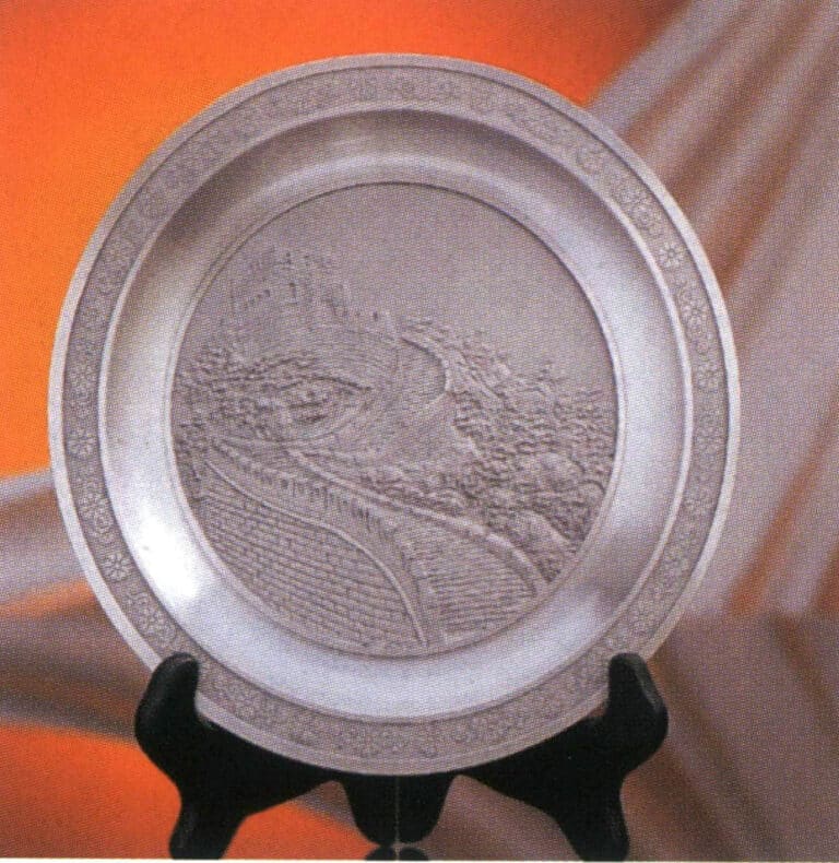
Tin plate
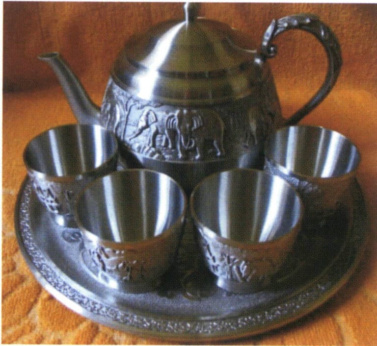
Tinpot and tin cup
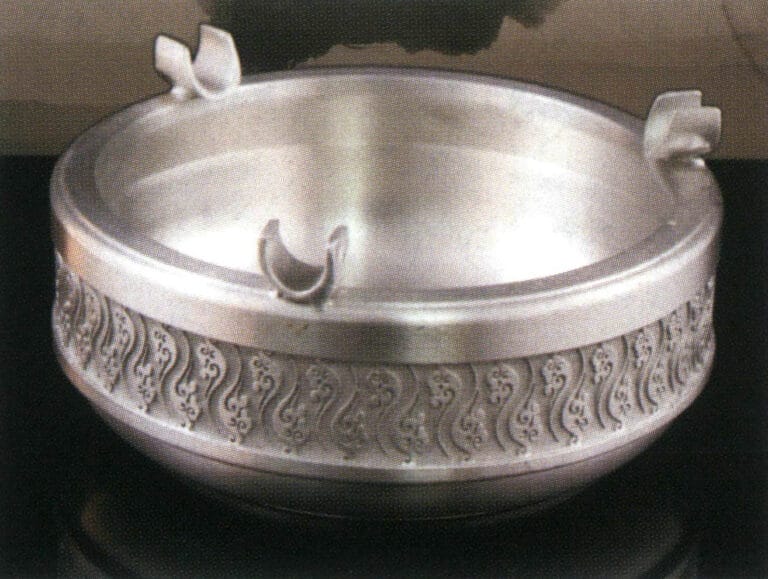
Tin alloy ashtray
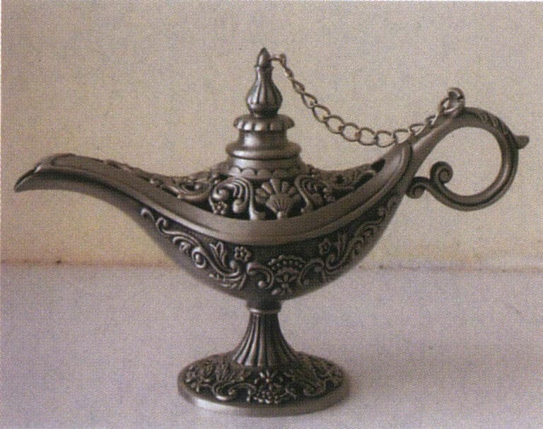
Tin alloy ornament
(2) Body jewelry
Lead-tin low melting point alloys can be made into various exquisite body jewelry. These jewelry are characterized by individuality and fashion, and they are inexpensive and increasingly favored by fashionable men and women. Most alloy jewelry has an electroplated layer (18K white gold, 18K gold, 925 silver). It is inlaid with zircon, crystal diamonds, pearls, or jade, making their appearance comparable to high-priced gold and silver jewelry. Common items include rings, necklaces, bracelets, earrings, brooches, buttons, tie clips, and hair accessories, with the main material being 3# lead-tin alloy.
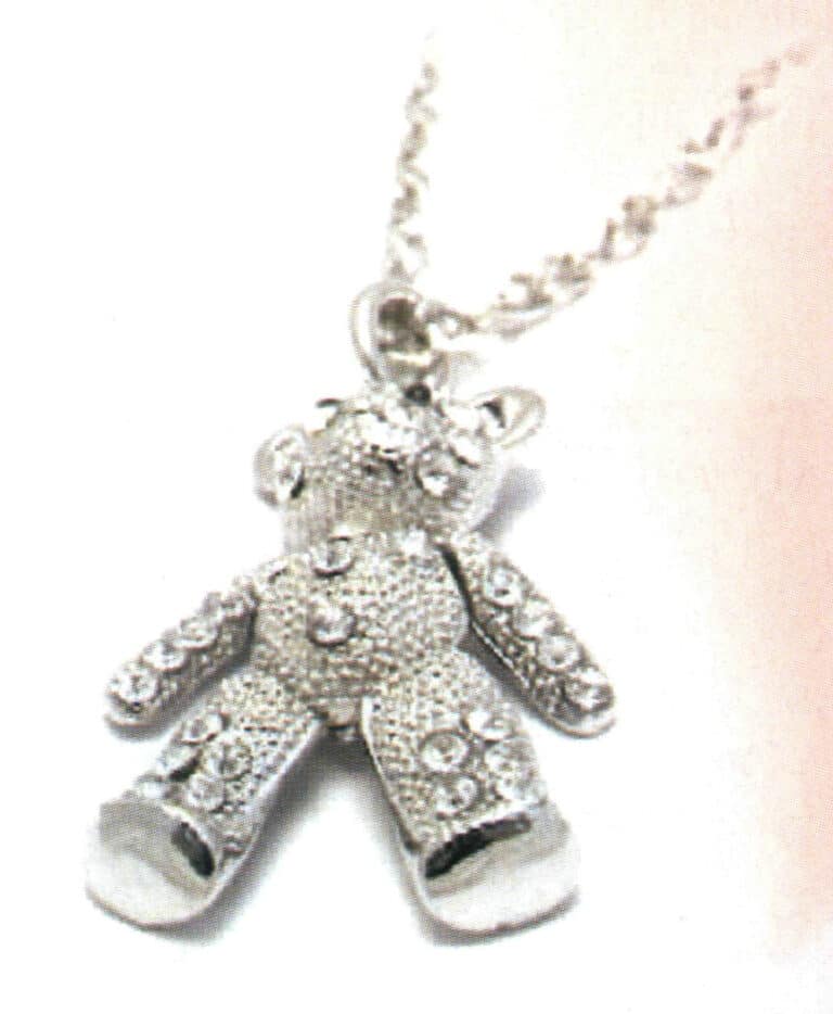
Lead-Tin alloy rhinestone pendant
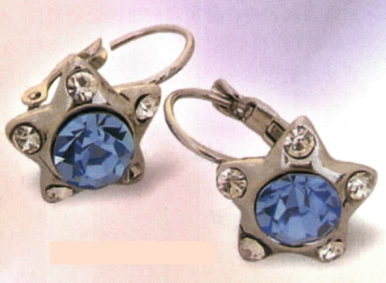
Lead-Tin alloy rhinestone earrings
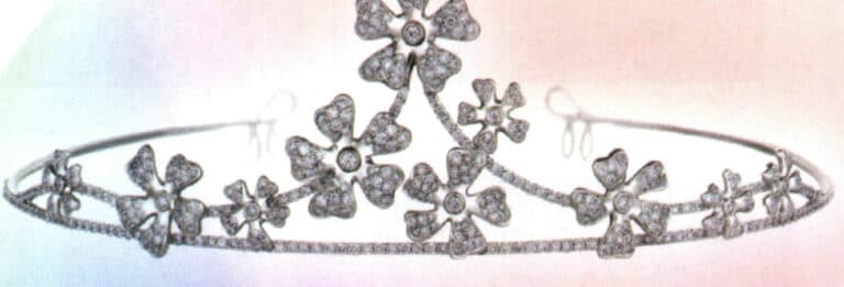
Lead-tin alloy rhinestone crown

Lead-tin alloy rhinestone hair clips

Lead-Tin alloy rhinestone rings
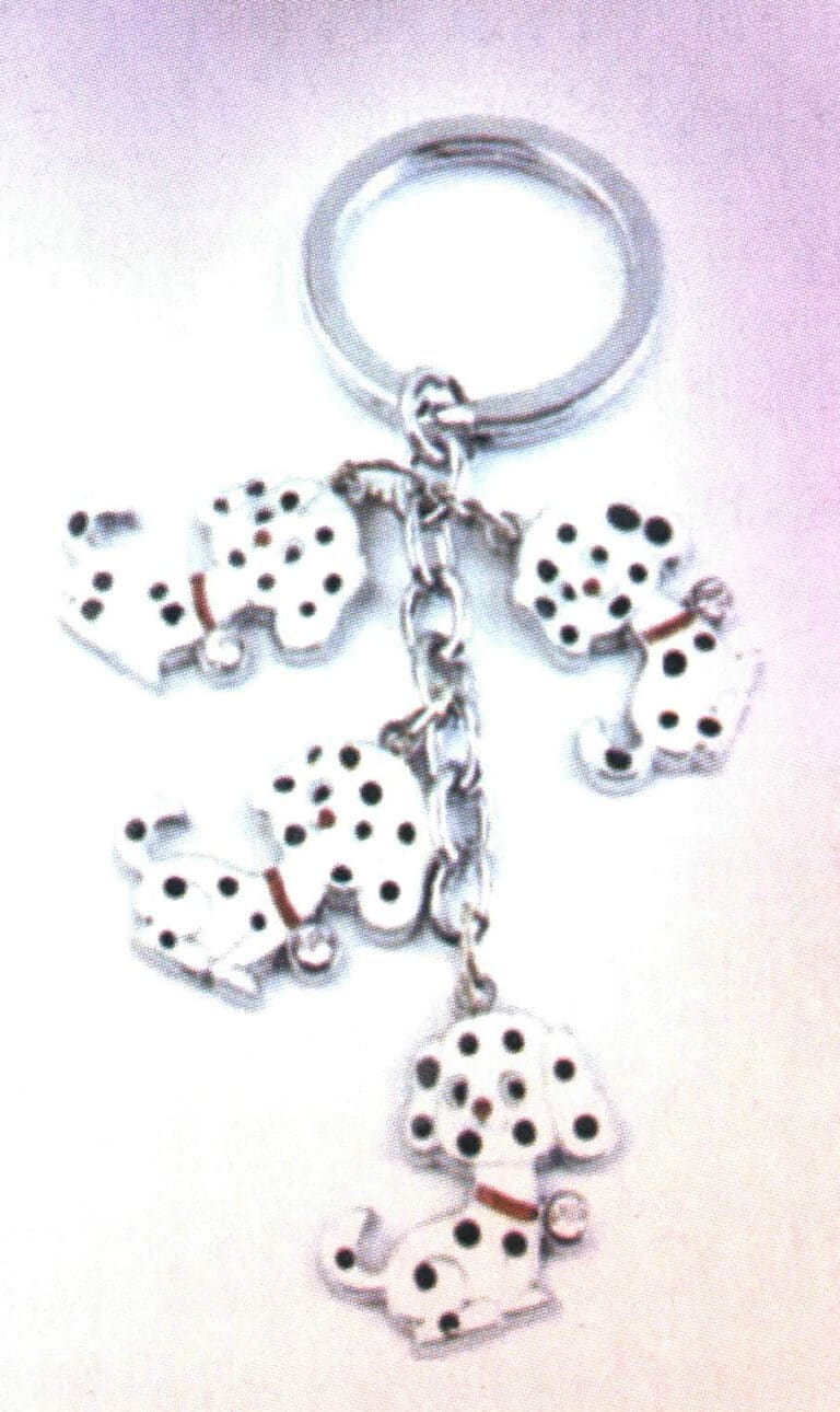
Lead-tin alloy keychain

Lead-tin alloy necklace
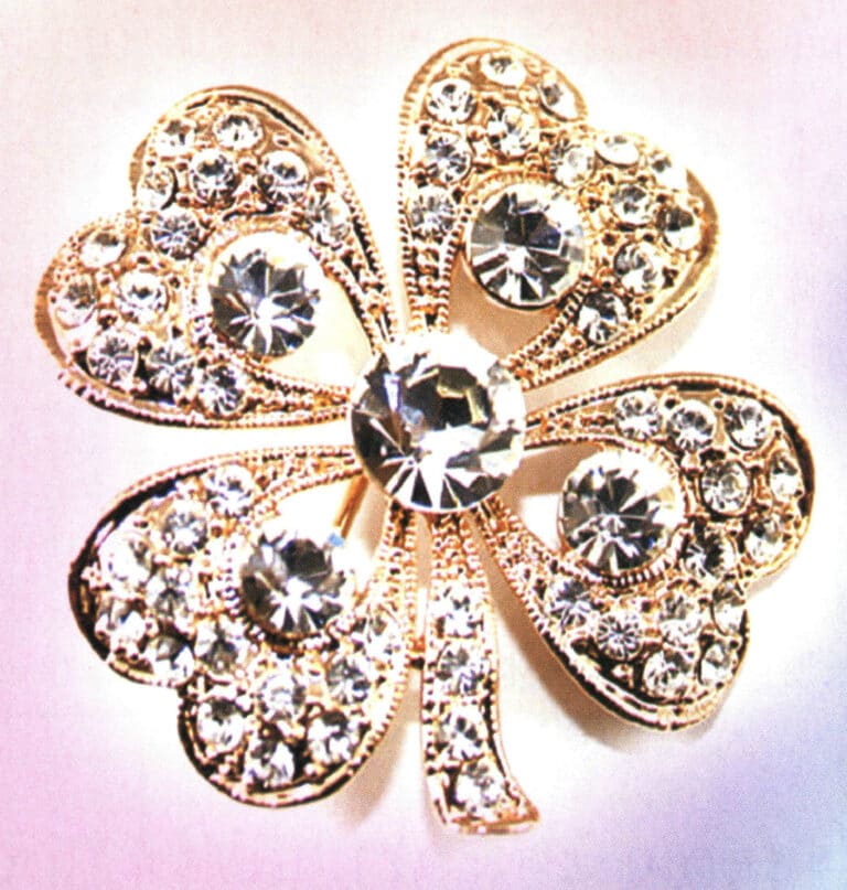
Lead-tin alloy corsage
4. Maintenance of Low Melting Point Alloy Jewelry
Lead-tin alloy jewelry with low melting points has a good simulation effect after surface treatment. However, if not properly maintained or worn, the jewelry can quickly show problems such as corrosion, discoloration, or even breakage. Therefore, it is necessary to maintain it correctly and reasonably, as detailed below:
(1) Jewelry should be changed frequently. The same jewelry should be avoided for long periods of wear, especially in hot summer weather, as the jewelry’s plating can easily wear off from prolonged contact with sweat. Therefore, it is best to prepare multiple jewelry pieces for regular replacement.
(2) Contact with chemical drugs can easily damage jewelry. The fragrance during bathing, chlorine in swimming, and salt in seawater can all cause corrosion to the jewelry’s plating, so all jewelry should be removed before bathing or swimming.
(3) Collisions can easily cause scratches; store them carefully. Do not stack the jewelry together; it should be stored in its original packaging or placed in a jewelry box with separate compartments to avoid collisions that can scratch the surface.
(4) Clean jewelry regularly, using a soft fine-bristle brush to sweep and wipe the surface of the jewelry to remove surface stains.
5. The Safety of Low Melting Point Alloy Jewelry
Metal elements play an extremely important role in human health; deficiency and excess can lead to diseases. However, some metal elements are harmful to human health, causing diseases and even death.
(1) Lead
Lead is a heavy metal and a highly polluting toxin. It can damage the blood, causing the breakdown of red blood cells, and spread through the bloodstream to all organs and tissues, entering the bones, leading to bone nerve paralysis and finger tremors. In severe cases, it can result in lead poisoning, encephalopathy, and death. The ancient Romans used lead vessels to store sugar and wine and cast water pipes from lead, which increased the lead content in food and water, causing chronic poisoning. An example is the presence of black spots of lead sulfide on bones after death.
Among all known toxic substances, lead is the most documented in books. Ancient texts record that using lead pipes to transport drinking water poses risks. Many chemicals may degrade into harmless final compounds after remaining in the environment for some time. Still, lead cannot degrade and remains available for a long time once released. Due to lead’s long-term persistence in the environment and its strong potential toxicity to many living organisms, it has consistently been classified as a strong pollutant.
(2) Cadmium
Cadmium poisoning can cause muscle atrophy, joint deformities, unbearable bone pain, inability to sleep, pathological fractures, and even death. The main source of cadmium is wastewater containing cadmium discharged from factories into riverbeds, irrigating rice fields, being absorbed by plants, and accumulating in rice. Long-term consumption of cadmium-contaminated rice or drinking water polluted by cadmium can easily lead to “bone pain disease.”
(3) Antimony
Experiments conducted by the International Antimony Association in its early years showed that if mice were exposed to high concentrations of antimony for a long time, inflammation will occur in the lungs, which can lead to lung cancer. However, in reality, people do not work for long periods in environments with high concentrations of antimony, and there have been no reported cases of lung cancer due to excessive inhalation of antimony. Nevertheless, its potential danger to the human body cannot be ruled out.
In addition to the toxic elements such as Cd, Pd, foundry workers should also be aware of the harmful effects of other alloy elements on the body such as Cu, Sn, Bi, Zn. Therefore, it is important to ensure good ventilation during casting and comply with laws regarding these elements’ proper use and exposure limits. The “Industrial Pollution” in the United States lists some typical metal elements and their hazards to various parts of the body (Table 4-4).
Research shows that some alloys without Pb and Cd can improve their casting performance by enhancing rubber composition, which, if feasible, would eliminate the need to use toxic elements.
Table 4-4 The Harm of Metal Elements to Body Organs
| Affected organs | Bi | Cd | Cu | Pb | Sn | Zn |
|---|---|---|---|---|---|---|
| Kidney | √ | √ | √ | |||
| Nerves | √ | √ | √ | |||
| Liver | √ | |||||
| Gastrointestinal | √ | √ | √ | √ | √ | |
| Respiratory organs | √ | |||||
| Hematopoietic tissues | √ | √ | √ | |||
| Bones | √ | √ | ||||
| Skin | √ | √ | ||||
| Cardiovascular | √ |
Section II Zinc Alloy Products
1. Zinc Alloy
Zinc alloy is a non-ferrous alloy composed of zinc as the base with the addition of other elements such as aluminum, copper, and magnesium. It is bluish-white, shiny, and hard and brittle. Zinc alloys can be divided into two categories based on processing technology: deformed and cast zinc. Cast zinc alloys have good fluidity and corrosion resistance, making them suitable for casting process products such as jewelry, instruments, and automotive parts housings.
Zinc alloys are mainly used for silicone rubber centrifugal casting and die casting according to the casting method.
1.1 Zinc Alloy for Centrifugal Casting of Silicone Rubber
Table 4-5 Low Melting Point Zinc Alloy Composition Table (According to American ASTMB240-01 Standard)
| Elementti | Zn | Al | Cu | Mg | Fe | Pb | Cd | Sn |
|---|---|---|---|---|---|---|---|---|
| Content /wt% | Margin | 3. 9 ~ 4. 3 | 0.75 ~ 1.25 | 0.03 ~ 0.06 | < 0.075 | < 0. 005 | < 0.03 | < 0. 002 |
This environmentally friendly alloy is free of lead, cadmium, and nickel. It is lightweight, has a good surface finish, forms quickly, effectively suppresses grain boundary corrosion, and prevents the formation of surface roughness and sand holes. It suits various industries, such as automotive, home appliances, machinery, watches, electrical appliances, instruments, hardware accessories, decorative gifts, and toy trademarks.
To increase the luster of accessories’ surfaces and meet the casting needs of high-gloss accessories, a zinc-magnesium alloy with magnesium as the main alloying element has been developed. This alloy is widely used in high-hardness, high-gloss hardware accessories such as pendants, earrings, hairpins, clothing, handbag buckles, belt buckles, shoe buckles, nameplates, etc. Its typical chemical composition is shown in Table 4-6.
Table 4-6 Typical Zinc-Magnesium Alloy Composition for Accessories
| Elementti | Zn | Mg | Al | Cu | Bi | Ag | Osoitteessa | Pb | Ni | Cd |
|---|---|---|---|---|---|---|---|---|---|---|
| Content /wt% | Margin | 12.4 | 3.5 | 0.06 | 0.06 | 0. 05 | 0.01 | 0.0003 | 0.0002 | 0.0019 |
The melting point range of zinc-magnesium alloy is 320-330℃. Generally, the casting temperature is 380-400℃, the grain is fine and uniform, the produced products have a smooth and shiny surface, no sand holes, a white luster with an oily feel, good fluidity, less oxidation, and slag inclusion, easy to polish, quick cooling, suitable for the requirements of large smooth surface products. The alloy is lead-free, cadmium-free, and nickel-free, classified as an environmentally friendly alloy, with a cost only 1/3 of 0# lead-tin alloy material, and the smooth surface is better than 0# lead-tin material. This alloy is lightweight, 50% lighter than lead-tin alloy 3# material, and 20% lighter than zinc alloy.
In addition, as corresponding materials for zinc-magnesium alloys, there are also magnesium-based alloy materials on the market that use zinc and aluminum as the main alloying elements, commonly referred to as magnesium-zinc alloys. The commonly used decorative magnesium-zinc alloy materials mainly fall into three categories.
(1) Magnesium-Zinc Alloy A Material
This alloy is suitable for producing ornaments and crafts that require a high gloss finish (over 5 cm). It has good fluidity, toughness, and gloss, is easy to polish and weld, does not bubble during electroplating, and has a melting point of around 300℃. It is on par with lead-tin alloy 1# material, but the price is only half that of lead-tin alloy 1# material.
(2) Magnesium-Zinc Alloy B Material
This alloy is suitable for moderately difficult smooth surfaces (about 3 cm). It has good fluidity, toughness, and smoothness and is easy to polish and weld. It is 20% lighter than material A and suitable for producing jewelry and crafts, with a melting point of about 320℃.
(3) Magnesium-Zinc Alloy C Material
This alloy is suitable for producing small smooth surface products with high strength and hardness (under 2 cm), has good fluidity and smoothness, is easy to weld and polish, and is lighter than the previous two, being the 1/3 of the lead-tin alloy #3. However, its toughness is poorer than the previous two, making it suitable for producing hard-strength products like hairpins and belt buckles, but not for hollow or perforated products with a melting point of 350-380℃.
The application range of magnesium-zinc alloys is quite broad, suitable for making various exquisite artistic castings, such as rings, necklaces, bracelets, earrings, brooches, buttons, tie clips, hat decorations, craft ornaments, religious emblems, miniature statues, souvenirs, belt buckles, and other craft accessories. These materials have the following characteristics:
- Stable performance, low melting point, good fluidity, small shrinkage.
- The grains are fine, with good toughness and appropriate hardness, a smooth surface, few sand holes, blemishes, and cracks, and good polishing and electroplating effects.
- Compliance with environmental protection requirements and health standards.
- Its lower melting point makes it suitable for silicone molds. Thus, the mold consumption cost is low, making it particularly suitable for producing castings in quick delivery and small batches.
1.2 Die-Casting Zinc Alloy
(1) Characteristics of Die-Cast Zinc Alloy
Zinc alloys are widely used in the die-casting industry to produce various structural and functional die-cast parts, which are closely related to the characteristics of the material. Zinc die-casting alloys have a low melting point and good fluidity, and the casting process allows the mold’s small parts to be filled, offering many advantages that other die-casting alloys lack, such as fast casting speed, low temperature, low energy consumption, and long mold life. This has led to their adoption by many jewelry companies, with a gradually increasing variety and expanding usage, forming a series of alloy products. One of the characteristics of these alloys is that they can be processed using hot chamber die casting machines, which is much faster than the production speed of high aluminum zinc alloys and aluminum alloys that must be cast in cold chamber die casting machines, and they are easy to process into relatively economical thin-walled die-cast parts, with surfaces that are also easy to process, paint, and electroplate. Furthermore, compared to bronze alloys, cast aluminum alloys, and cast iron, zinc alloys have the advantages of low processing energy consumption, low cost, and good mechanical properties.
(2) Types of Die-Cast Zinc Alloys
With the improvement of product zinc grades, zinc alloys developed. By the early 1930s, the composition had stabilized. During this period, the New Jersey Company in the United States (now known as the American Zinc Company) developed the famous Zamak series of alloys, which gained worldwide recognition and became synonymous with die-casting alloys. The Zamak series of alloys was developed according to the requirements of different production processes and product structural performance, and different zinc alloys have different physical properties and mechanical properties, which provides options for the design of die-cast parts.
Common types of die-cast zinc alloys include:
- Zamak 3. Castings with good fluidity and mechanical properties are used for applications requiring low mechanical strength, such as toys, lamps, decorations, and electrical components.
- Zamak 5. Good fluidity and mechanical properties are used in castings with certain requirements for mechanical strength, such as automotive parts, electromechanical parts, mechanical components, and electrical assemblies.
- Zamak 2. Used for mechanical parts with special requirements for mechanical performance, high hardness requirements, and general dimensional accuracy requirements.
- ZA8. Good fluidity and dimensional stability, but poor fluidity, applied to small die-casting parts with high precision and mechanical strength requirements, such as electrical components.
- Superloy. It has the best fluidity and is used for die-casting thin-walled, large-sized, high-precision, complex-shaped workpieces, such as electrical components and their enclosures.
The composition requirements of the alloys mentioned above are shown in Table 4-7.
Table 4-7 Standard Alloy Composition of Zinc Alloys
| Alloy Category | Zamak 2 | Zamak 3 | Zamak 5 | ZA8 | Superloy | AcuZinc 5 |
|---|---|---|---|---|---|---|
| Aluminum | 3.8 ~ 4. 3 | 3.8 ~ 4. 3 | 3.8 ~ 4. 3 | 8. 2 ~ 8. 8 | 6. 6 ~ 7. 2 | 2. 8 ~ 3. 3 |
| Kupari | 2. 7 ~ 3. 3 | < 0.030 | 0. 7 ~ 1. 1 | 0. 9 ~ 1. 3 | 3. 2 ~ 3. 8 | 5. 0 ~ 6.0 |
| Magnesium | 0.035 ~ 0.06 | 0.035 ~ 0.06 | 0.035 ~ 0.06 | 0.02 ~ 0.035 | < 0. 005 | 0.025 ~ 0.05 |
| Rauta | < 0.020 | < 0.020 | < 0.020 | < 0.035 | < 0. 020 | < 0.075 |
| Lead | < 0. 003 | < 0. 003 | < 0. 003 | < 0.005 | < 0. 003 | < 0.005 |
| Cadmium | < 0.003 | < 0.003 | < 0.003 | < 0. 005 | < 0.003 | < 0. 004 |
| Tin | < 0.001 | < 0.001 | < 0.001 | < 0.001 | < 0.001 | < 0. 003 |
| Zinc | Margin | Margin | Margin | Margin | Margin | Margin |
| (Lu Hongyuan, 1997; Wu Chunmiao, 2003) | ||||||
(3) The Effect of Alloying Elements on the Properties of Zinc Alloys
In the composition of die-cast zinc alloys, effective alloying elements such as aluminum, copper, and magnesium and harmful impurity elements such as lead, cadmium, tin, and iron are present. The effects of these elements on the alloy’s properties are as follows.
① Aluminum. Aluminum can improve the casting performance of alloys, increase the fluidity of alloys, refine grains, cause solid solution strengthening, and enhance mechanical properties; in addition, aluminum can reduce the reactivity of zinc with iron, decreasing the impact on ferrous materials, such as gooseneck, mold, erosion of the crucible.
The aluminum content is generally controlled between 3.8%-4.3%. This is mainly due to the required strength and fluidity; good fluidity is a necessary condition for obtaining castings with complete shapes, precise dimensions, and smooth surfaces.
② Copper. The role of copper in zinc alloys includes increasing the hardness and strength of the alloy, improving the wear resistance of the alloy, and reducing intergranular corrosion.
However, to control the copper content in zinc alloys, when the copper content exceeds 1.25%, it will cause changes in the dimensions and mechanical strength of the die-cast parts due to aging; additionally, it will reduce the alloy’s ductility.
③ Magnesium. Magnesium’s role in zinc alloys includes reducing intergranular corrosion, refining the alloy structure, thereby increasing the strength of the alloy, and improving its wear resistance.
Magnesium is a very active element that easily oxidizes and is lost in the molten state of alloys. When the magnesium content is more than 0.08%, the alloy becomes thermally brittle, with reduced toughness and flowability.
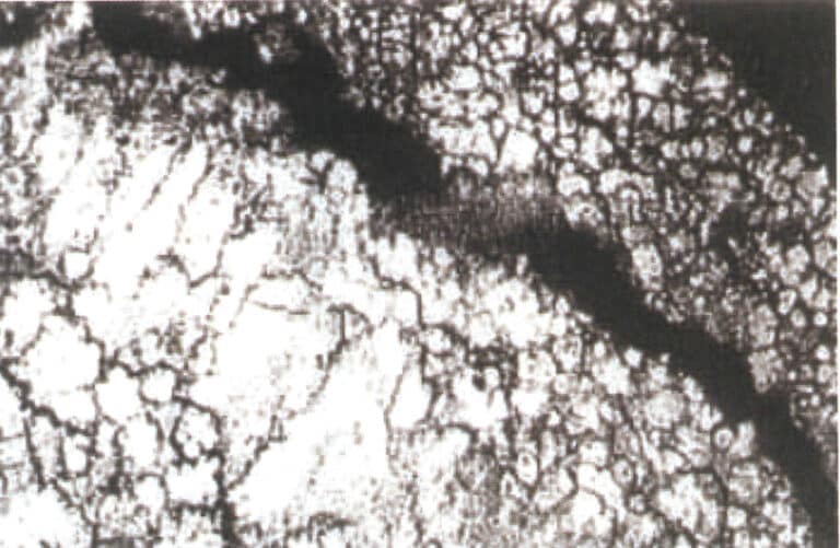
④ Impurity elements: lead, cadmium, tin. The aforementioned impurity elements make the intergranular corrosion of zinc alloys very sensitive, accelerating its intergranular corrosion in warm, humid environments (Figure 4-2), reducing the alloy’s impact resistance, lowering the alloy’s tensile strength, thereby reducing mechanical properties, and causing dimensional changes in castings. The cadmium and lead content in the alloy must not exceed 0.003%, the tin content in zinc alloy ingots must not exceed 0.001%, and the content in large castings must not exceed 0.002%. When the content of impurity elements lead and cadmium in the zinc alloy is too high, the surface quality of the workpiece appears normal immediately after die casting, but after being stored at room temperature for some time (8 weeks to several months), blisters appear on the surface.
⑤ Impurity element: Iron. The iron element can increase the hardness of zinc alloys, but the iron content in zinc alloys must not exceed 0.02%; otherwise, it will increase the brittleness of the alloy. Iron reacts with aluminum in the zinc alloy to form intermetallic compounds Al5Fe2, causing the loss of aluminum and forming slag; it forms hard spots in die-cast parts, affecting subsequent processing and polishing, and scratches are likely to appear on the surface during polishing; it increases the brittleness of the alloy.
⑥ Impurity element: Silicon. The content of silicon in zinc alloys must not exceed 0.02%. Otherwise, it will increase the brittleness transition temperature of the zinc alloy and reduce its processing performance.
(4) Selection of Die-Cast Zinc Alloys
There are many die-cast zinc alloys, and the choice of which zinc alloy to use mainly depends on three aspects.
① The purpose of the die-cast part itself. The performance requirements that must be met include:
- Mechanical properties, such as tensile strength, elongation, hardness, etc. Tensile strength is the maximum resistance of the material at the time of fracture; elongation is a measure of the material’s brittleness and plasticity; hardness is the resistance of the material’s surface to plastic deformation caused by pressing or friction with hard objects.
- Working environmental conditions, including working temperature, humidity, the medium in contact with the workpiece, and airtightness requirements.
- Precision requirements, including achievable precision and dimensional stability.
② Good process performance. It includes casting process performance, machinability, and surface treatment process performance.
③ Good economy. The cost of raw materials, production equipment requirements (including melting equipment, die-casting machines, molds, etc.), and production costs.
2. Examples of Zinc Alloy Jewelry

Zinc alloy pendant
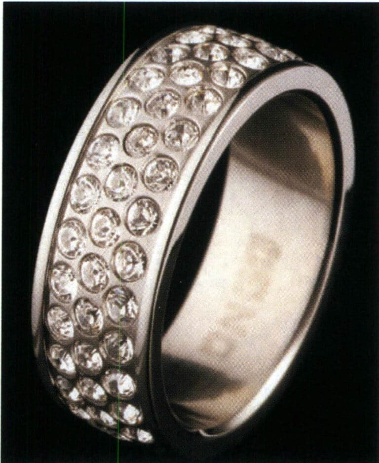
Zinc alloy ring

Zinc alloy keychain
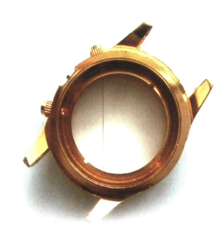
Zinc alloy case
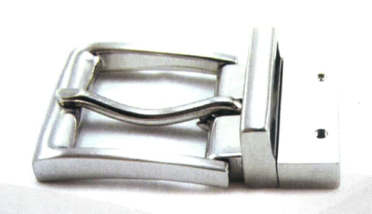
Zinc alloy strap buckle
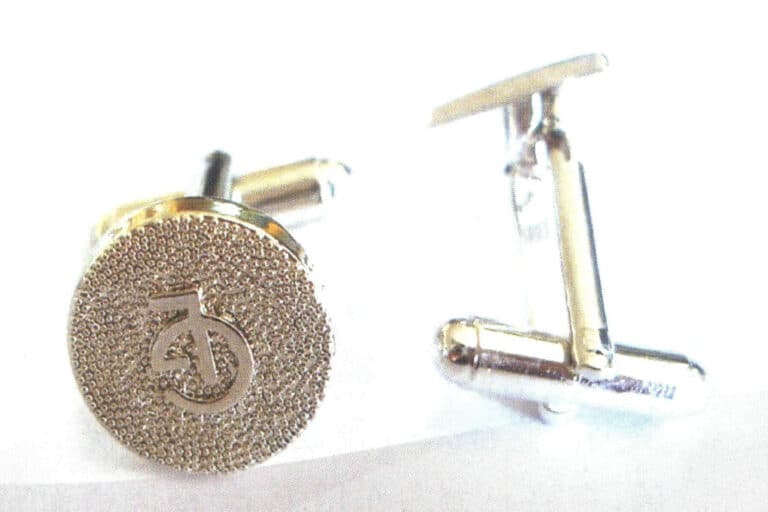
Zinc alloy cufflinks

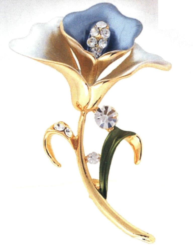
Sinkkiseos rintaneula
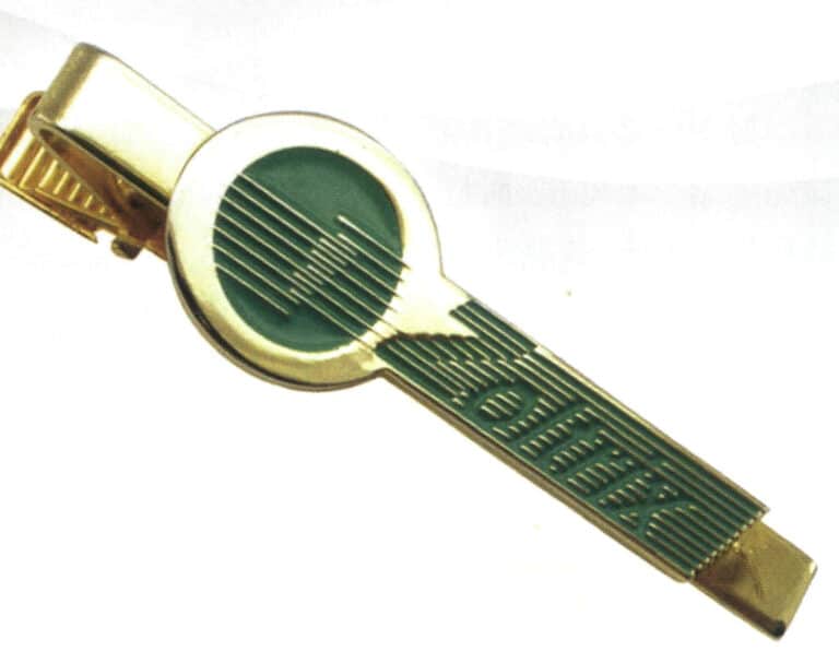
Zinc alloy tie clip
Section III The Production Process of Low Melting Point Alloy Craft Jewelry
1. Silicone Rubber Centrifugal Casting Process
1.1 Introduction to the Centrifugal Casting Process
1.2 Characteristics of Silicone Rubber Centrifugal Casting Process
Due to the low melting point of alloy jewelry, creating a gypsum mold like cast gold, silver, and copper alloys is unnecessary. Instead, soft molds made of heat-resistant silicone rubber are used for production, which can greatly reduce production costs and improve production efficiency.
Centrifugal casting of gold jewelry is carried out using the centrifugal pressure casting method. After the molten metal is poured into the mold, as the mold rotates, the molten metal is subjected to centrifugal force, generating filling pressure that forces the molten metal to fill the cavity smoothly. The centrifugal force F=m·r·w2, where F is the centrifugal force, m is the mass of the molten metal, w is the radius of rotation of the mold, and is the angular velocity. It can be seen that the larger the radius of rotation and the faster the rotation speed, the greater the centrifugal force generated. Since the molten metal fills and solidifies under centrifugal force, the metal has good shrinkage compensation, resulting in a dense structure and good mechanical properties of the castings; hollow castings do not require risers, significantly improving metal utilization.
However, compared to negative pressure casting, centrifugal casting has disadvantages such as severe turbulence of the molten metal during pouring, a tendency to produce gas holes, strong erosion of the mold wall by the molten metal, and a relatively small maximum amount of metal that can be cast. In addition, castings produced by the centrifugal casting method are prone to thermal cracking defects, especially at high rotational speeds.
1.3 Silicone Rubber Centrifugal Casting Production Process
Low melting point alloy jewelry mainly uses a silicone rubber centrifugal casting process, and its process mainly includes the following aspects.
(1) Jewelry Development
Jewelry development is the first step in creating jewelry from scratch, serving as a guide and reference for subsequent steps, and is also an important link in fully expressing the individuality of the jewelry. Designers form their initial ideas by synthesizing and categorizing information from various aspects and then representing them on flat drawings. Once the drawings are completed, they are handed over to the sample making room, where the sample maker creates a three-dimensional master model using alloy materials according to the requirements of the drawings. Completing the master model concludes the main process of jewelry development.
(2) Molding
The completed master model is transferred to the molding room, where the mold maker creates molds made of special rubber. The molding process is key to the transition from a single piece of jewelry to mass production, and the quality of the mold directly affects the yield of the next process.
① Types of rubber raw materials. In producing low melting point alloy centrifugal casting, models made of silicone rubber are widely used, with a small amount of natural rubber and silicone rubber. The comparison of the two types of rubber model materials is shown in Table 4-8.
Table 4-8 Comparison of Natural Rubber and Silicone Rubber
| Parameter | Natural rubber | Silicone rubber | |||||||
|---|---|---|---|---|---|---|---|---|---|
| 1#black | 2#black | 3#black | White | Natural | 60 - D | 70 - D | 58 - D | 65 - D | |
| Relative hardness | 60 | 65 | 70 | 66 | 42 | 60 | 70 | 58 | 65 |
| Density/(g·cm-3 ) | 1.24 | 1.26 | 1.17 | 1. 55 | 1.07 | 1.6 | 1. 73 | 1.44 | 1.56 |
| Tear strength/MPa | 2.34 | 2.09 | 3. 00 | 1.94 | 0.68 | 0. 74 | 0.69 | 1.01 | 0. 63 |
| Bending modulus/MPa | 2.20 | 2.17 | 3. 58 | 2.41 | 1.72 | 1. 86 | 2.41 | 1.31 | 2.27 |
| Tensile strength/MPa | 3.79 | 3.79 | 2.41 | 3.45 | 3.93 | 2. 55 | 2.41 | 3.58 | 1.38 |
Rubber generally contains fillers, catalysts, active agents, retarders, antioxidants, plasticizers, and other materials. Uncured materials should be stored in a cool place, and cured models should be kept as far away from light as possible, as ozone can damage the materials.
During production, slightly softer rubber materials are generally preferred because they are easier to mold and allow for moveable blocks. The hardness of rubber used for accessories after vulcanization is generally around 60-80, and in actual production, about 70% of the rubber types have a relative hardness of with hardness of 65, and there is also 5% with a hardness of 70.
The lower the hardness of the rubber model, the more it shrinks, so the foundry workers and model makers must collaborate to take measures to compensate for its shrinkage value. The shrinkage value is related to the placement of the workpiece during casting; for the same product, the shrinkage value can vary significantly using different placement methods. The production of some special workpieces depends on the operator’s experience.
② Making rubber sheets. Mix new rubber and recycled rubber, using a ratio of 50/50. The rubber is heated in a molding machine and pressed into sheets with a thickness of 1.3-1.5mm, which is one layer of the rubber mold. The material is rolled up in a cylindrical barrel and cut into small pieces of the required size. The material is stacked on a pallet and placed in a cooling chamber (the cooling chamber temperature is about 6℃), for 3-4 days, allowing the rubber to shrink to its final size. The total shrinkage of the material during the entire process may reach 11%. If the final shape of the material is egg-shaped, it may be due to insufficient cooling. The material is usually removed from the cooling chamber and cut into circular pieces of the desired diameter, usually 8’’-18’’. In Figure 4-3, rubber A is used as the surface layer of the model, featuring high-temperature resistance, low shrinkage, strong tear resistance, and durability. In contrast, rubber B is used as the reinforcement layer of the rubber model, mainly serving to support and reinforce.
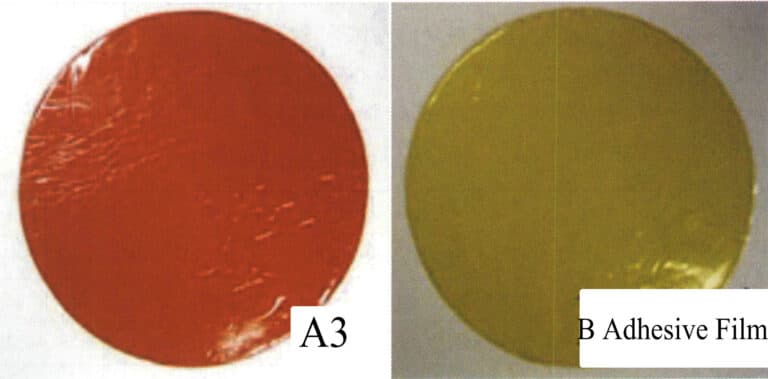
Figure 4-3 Silicone rubber sheet
Film A is used as the surface layer; Film B is used as the reinforcement layer
③ Press the rubber mold. The quality of the rubber mold directly determines the quality of the casting. A high-quality rubber mold requires reasonable distribution of the original model, sprues that facilitate filling and venting, easy removal of the casting, and resistance to deformation and breakage, among other factors. The following are the basic steps for making a rubber mold.
Step one is preparation. Prepare various tools and auxiliary materials needed for mold pressing (Figure 4-4).
Place the mold frame into the press for preheating to 150℃ or according to the recommended temperature from the rubber supplier, usually 146-157℃; separate the top and bottom of the mold base, and sprinkle with a release agent to prevent the two halves from sticking together or sticking to the mold frame; clean the dust off the surface of the original model, spray with silicone to facilitate separation from the silicone rubber mold, preventing sticking. Place newspaper under the steel plate and put the round disc into the steel ring (Figure 4-5).
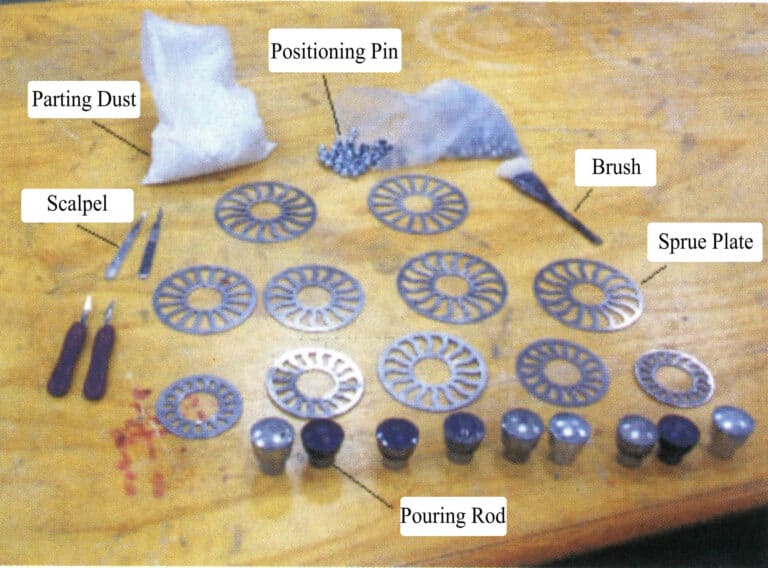
Figure 4-4 Tools and auxiliary materials required for molding
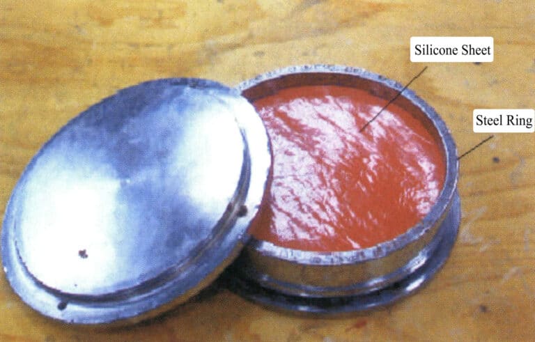
Figure 4-5 Silicone plate placed inside the steel ring.
In the second step, a hole is drilled in the center of the upper half of the membrane disc, and the pouring rod and pouring basin are placed in the center (Figure 4-6).
In the third step, arrange the master model and positioning pins in a reasonable order and at the required distance around the pouring plate on the surface of the lower mold (Figure 4-7). If the original model is very large, it is necessary to dig out part of the rubber from the bottom mold.
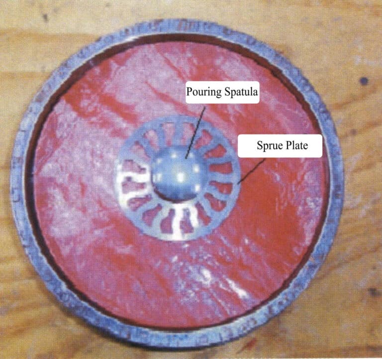
Figure 4-6 Placing the pouring disc
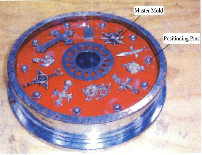
Figure 4-7 Place the master model and positioning pin in the lower half of the mold
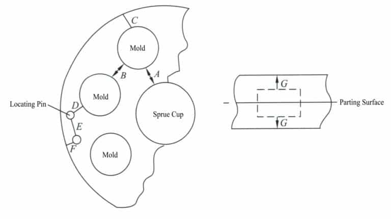
Experiments show that the distance from the outer periphery to the mold’s center gate significantly impacts the casting’s quality. The closer the workpiece is to the center gate, the larger the cross-section of the runner must be to ensure the forming rate and the density of the solidified structure. In addition, the original models within the same rubber mod should preferably have similar shapes, as this not only improves the completion rate of the castings but also results in a more uniform composition of the finished products; if the shape differences are too great, it may lose balance and vibrate during the casting rotation.
In the fourth step, evenly sprinkle the release powder on the mold release surface and use a brush to remove the release powder from the model (Figure 4-9).
In the fifth step, place the upper half of the mold into the mold frame, carefully position it, and place the upper-pressure plate into the mold frame, ensuring both are vertical (Figure 4-10).
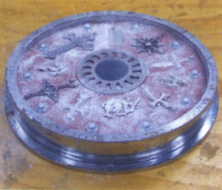
Figure 4-9 Spraying powder on the profiling surface
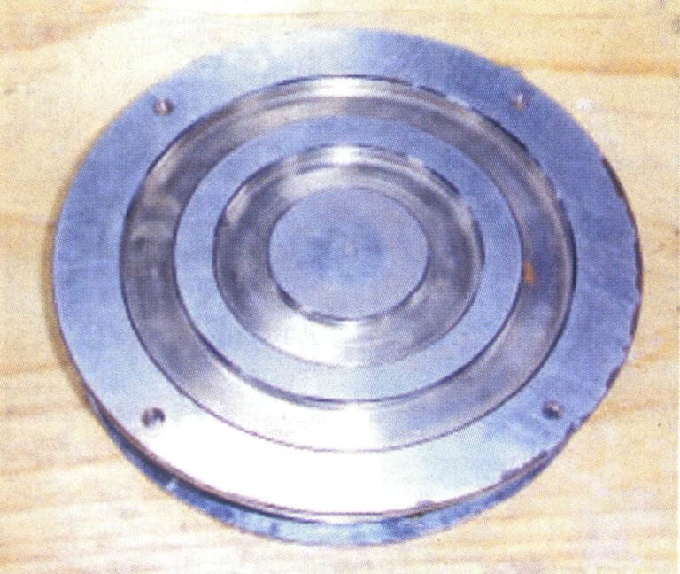
Figure 4-10 Mold assembly
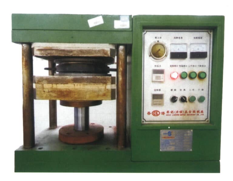
In the six step, place the mold frame into the press machine, ensuring it is straight and positioned in the center of the press machine. Raise the platform and mold frame to engage with the upper platform and observe the fit condition (Figure 4-11). Gently apply pressure to raise the platform, release the pressure and repeat the previous operation, applying pressure in small amounts each time. A general molding machine relies on a feel, while an automatic molding machine has a pressure gauge. Repeat this step for 8-15 minutes until the rubber is very soft and the platen is completely sealed.
In the seven step: set the Vulcanization time, generally at least 1 hour for each inch of thickness. When the curing time is up, release the pressure and remove the mold frame.
Copywrite @ Sobling.Jewelry - Custom korujen valmistaja, OEM ja ODM korut tehdas
(3) Cutting Mold
① Open the mold frame with a wrench or screwdriver, remove the rubber mold from the mold frame, cut the two halves of the rubber mold with a scalpel or saw blade, make alignment marks on the edges of the rubber mold, and remove the excess flash (Figures 4-12 and 4-13).
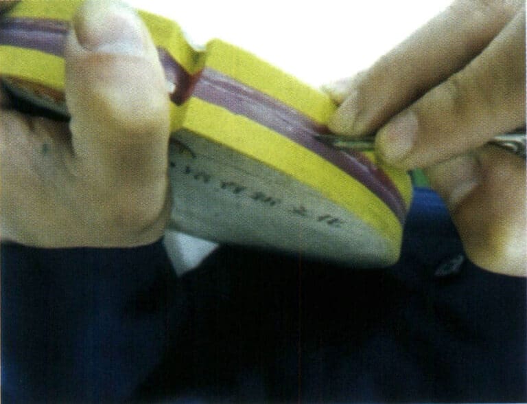
Figure 4-12 Cutting mold
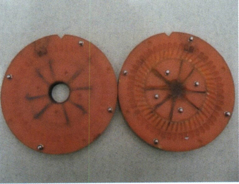
Figure 4-13 Opened adhesive rubber mold
② Remove the original model from the mold and cut the sprue and ventilation line.
The establishment of sprues and ventilation lines has a significant impact on the quality of centrifugal casting. In the centrifugal casting of low melting point alloy jewelry, the molten metal enters the mold cavity through the pouring cup, horizontal runner, and sprue. The basic principle of opening sprues is similar to that in precious metal casting; the sprue must be large enough to ensure good shrinkage compensation, and ventilation lines must be established to allow gas to be smoothly discharged. Cutting the mold should be done smoothly to reduce turbulence during the flow of molten metal, and the sprue should be located at the thickest part of the casting.
a.Pouring system. A pouring cup model forms a pouring cup at the bottom of the rubber mold.
The horizontal pouring system consists of a series of channels that allow molten metal to flow from the pouring cup into the inner runner. The channels first radiate outward from the pouring cup to connect to the runner circle and then connect from the runner circle to the inner runner (Figure 4-14). This pouring system is beneficial for filling and prevents slag and impurities from entering the mold cavity.

The inner runner supplies molten metal to the mold cavity; it is the channel through which the molten metal flows from the horizontal runner into the mold cavity. The inner runner must be large enough to continuously compensate for the shrinkage of the molten metal as it solidifies in the cavity, and it should be located at the thickest part. At the connection point with the workpiece, it is generally tapered to facilitate the separation of the inner runner from the workpiece unless it is necessary to make it the same thickness as the workpiece.
b.Type of gating system. Direct pouring gating: usually used only for simple workpieces, this type of gating causes significant turbulence, and its advantage is that it increases the quantity of each type of workpiece.
Reverse gating system: The gating system first passes through the workpiece and then connects to the cavity from the back of the workpiece near the edge of the mold. Its advantages are that the casting quality is good, impurities and slag will not enter the cavity, and it reduces turbulence during filling.
Side gating system: It enters from the side of the workpiece and, like the reverse gate, occupies the space of the mold, but the quality of the workpiece is better. This type of gate can have various properties.
Horizontal gating system: It refers to the channels in the gating circle and spoke gating system, which serves to ensure smooth filling, avoid direct filling of molten metal, and thus help obtain clean workpieces.
Top gating system: This type of pouring gate is the opposite of the bottom pouring gate, where the material enters the cavity from the top of the workpiece. Generally, the pouring gate is located in the lower half of the mold, but if there are issues during filling, it can be set in the upper half of the mold. This type of pouring gate is beneficial for workpieces with large surfaces and thin walls.
In addition to directing molten metal into the mold cavity, the pouring system has other functions. For example, aside from the direct gating system, other pouring systems can have a slag collection area to gather slag and impurities from the molten metal, preventing them from entering the mold cavity; they can also allow gases to escape from the mold cavity. However, due to the high speed of centrifugal casting, relying solely on the pouring system is insufficient to expel all gases, so vent lines need to be established. Figure 4-15 is a schematic diagram of different types of pouring systems.
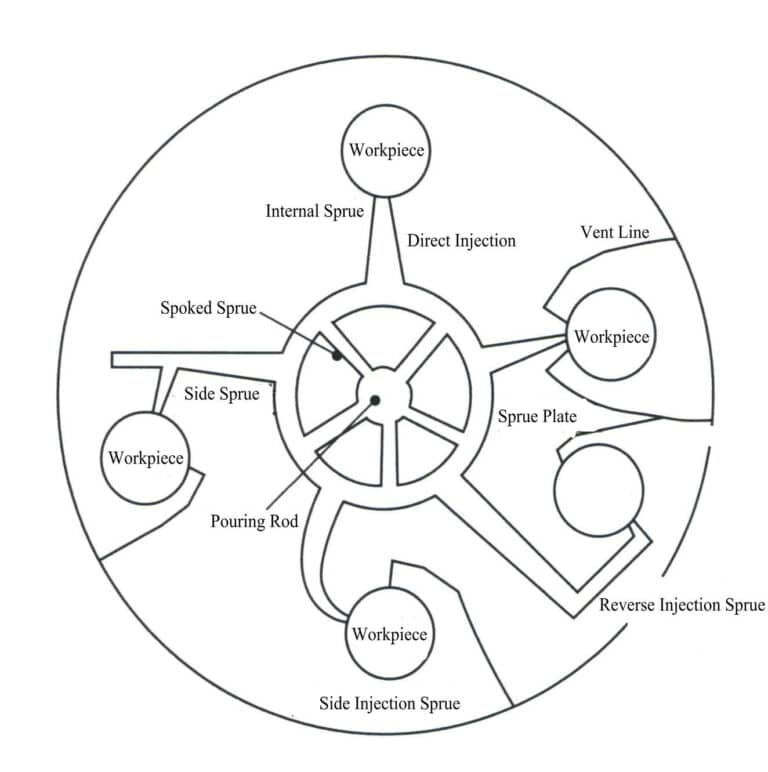
c. Cutting rubber mold sprue. Setting the sprue for the rubber mold is the most skillful task in the production of the rubber mold, and the basic steps are as follows:
After vulcanization of the rubber mold, it is better to cut the mold when there is a warm feeling by hand. The first step of cutting the mold is determining the sprue’s position and pouring gate. When no shaped pouring cup is used, the pouring cup should be cut out first, and the layout of the pouring gate can be drawn out by using a compass and other scribing tools, including the pouring gate and spokes from the pouring cup to the pouring circle, the transverse pouring gate, and the channel from the sprue circle to the workpiece. It is best to avoid directly filling the cavity with liquid metal, which should first flow through the cross pouring gate and the pouring system to ensure mold filling and help prevent impurities and slag from entering the cavity.
The mold cutting knife is placed at an 45 angle to the drawn line. First, cut out the pouring channel circle (Figure 4-16), about 12.5 mm wide and 6 mm deep in the center. Continuously cut along the inner and outer sides of the drawn runner circle to ensure smoothness, then remove the cut rubber material to obtain a runner circle shaped like a “V” (Figure 4-17).
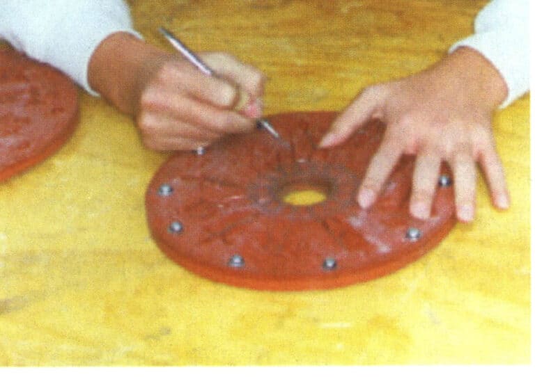
Figure 4-16 Cutting mold technique
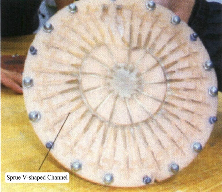
Figure 4-17 V-shaped sprue
The runner and the spoke runner should be cut out by cutting the runner circle, and a sufficient number of runners should be provided to ensure good filling of the molten metal. Generally, 4-5 spoke runners from the pouring cup to the runner circle is sufficient.
Cut the inner runner from the pouring circle to the workpiece. The inner runner is the part that connects the runner to the workpiece; it should not be a continuation of the transverse runner but rather a compensation for it to achieve optimal efficiency. The inner runner compensates and shrinks the workpiece; when cleaning, it should be knocked off from the casting. The inner runner should be large enough but should not cause cleaning difficulties. It is best to start cutting the inner runner at the workpiece as follows: neck down at the workpiece cut a very narrow channel with a thickness of about 5 mm; cut a channel towards the pouring circle, gradually increasing the depth and width, with a width of 12.5 mm and a depth of 6 mm at the pouring circle (approximately equal to the width of the pouring circle at the junction of the two inner runners).
If a top gating system is needed, the same method described above should be used for cutting. However, talcum powder should be used to complete the runner layout; the talcum powder will imprint the position of the workpiece in the lower half of the mold onto the corresponding position in the upper half of the mold, and cutting can be done based on these imprints.
d. Set up vent lines. The rubber mold’s vent lines must ensure that the gas in the cavity is smoothly discharged during the casting process to obtain high-quality castings. The vent lines here are very similar to those in the rubber mold during wax injection in investment casting. Just as talcum powder is dusted on the rubber mold during wax injection, talcum powder is also dusted on the rubber mold when centrifugally casting low-melting-point alloys to allow gas to be smoothly discharged outside the rubber mold.
There are two commonly used forms of vent lines, and their size depends on the size of the casting and the amount of gas that needs to be discharged. One is the conical vent line, which is very similar to the inner runner but much smaller, gradually tapering from the workpiece outward. The other, most commonly used, is the inner runner vent line, similar to the conical vent line but larger, allowing more gas to be discharged. When creating vent lines, the opening at the workpiece should be as small as possible to prevent molten metal from flowing in, but it should also be large enough to allow gas to escape quickly.
Since the workpiece is filled from the outer wall of the cavity towards the center, the inner runner should be set at the last filled area. If follow the imaginary straight line from the pouring cup to the center of the workpiece, this point should be the closest to the pouring cup. The inner runner is usually located at the tail end of the workpiece closest to the pouring cup. Most vent lines are cut similarly to the inner runner but are much smaller and established from the workpiece’s key points towards the cavity’s periphery. Sometimes, vent lines are also passed through the bottom of the mold, and then vent lines are established at the back, leading to the edge of the mold. Some manufacturers also use a vacuum during casting to assist with venting, a vacuum centrifugal casting process. The forms of vent lines are as follows:
Runner vent line: Often used with the direct inner runner, connected to the workpiece at an angle of 45°, then opened from one or both sides of the workpiece to the edge of the mold.
Drilling vent line: Used in situations where there is insufficient space in the mold, a gas collection point is set within the cavity, and a hole is drilled to the back of the mold at this point, then a ventilation line is drawn from the hole at the back of the mold to the edge of the mold. When making large workpieces, multiple ventilation holes may sometimes be drilled, drilling at an angle of 45° from the part of the workpiece close to the inner runner towards the back of the mold and then drawing ventilation lines from these to the edge of the mold at the back.
Vent holes: This ventilation method involves drilling holes in any part of the workpiece towards the back of the mold and creating vent lines. The reason for creating such vent holes is that gas can easily form back pressure during filling when blind holes are in the cavity, leading to poor filling. The diameter of a typical vent hole is 1 mm.
Air-collecting vent lines: They are composed of a series of conical vent lines drilled into the back of the mold and then opened on the back. They are usually used in areas of the workpiece that are difficult to fill completely.
Auxiliary vent line: It is opened along the side of the inner runner in the direction of rotation or on the edge of the reverse inner runner, drilled to the back of the mold, and its function is to assist the inner runner’s venting capability.
Figure 4-18 shows the opening methods of the pouring system for some typical ornaments.
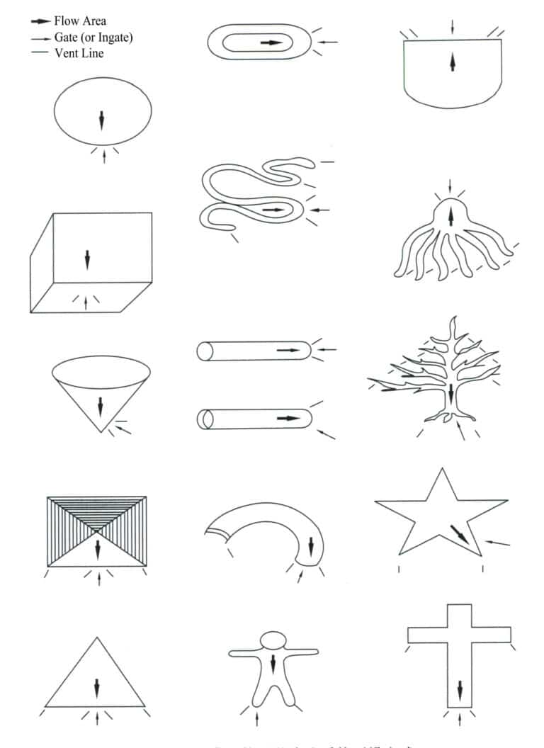
e. Use a scalpel to mark the side of the disc for alignment.
(4) Smelting
Alloy melting is an important part of the casting process. The melting process not only obtains molten metal but, more importantly, achieves a chemical composition that meets specifications, allowing the castings to have a good crystalline structure and minimal gas and inclusions in the molten metal.
During the melting process, the interaction between the metal and gas and between the molten metal and the crucible causes changes in the components, resulting in inclusions and gas absorption. Therefore, formulating the correct melting process specifications and strictly adhering to them is an important guarantee for obtaining high-quality castings.
① Oxidation and burning loss of metals. Oxidation and burning loss inevitably occur during the metal smelting process, and the following factors influence the extent:
a. The properties of metals and oxides. The affinity of metals for oxygen and the oxide film’s properties significantly impact oxidation loss. Elements with a high affinity for oxygen and a loose, porous oxide film experience greater oxidation loss, such as magnesium and lithium, which oxidize preferentially; aluminum and beryllium have a high affinity for oxygen, but the a of oxide film>1, allowing for the formation of a dense oxide film that reduces oxidation loss. Table 4-9 shows the a values of some oxides at room temperature.
Table 4-9 Approximate a Values of Certain Oxides at Room Temperature (Geng Haoran et al., 2006)
| Me | Mg | Cd | Al | Pb | Sn | Ti | Zn | Be | Ni | Cu | Cr | Fe |
|---|---|---|---|---|---|---|---|---|---|---|---|---|
| MexOy | MgO | CdO | Al2O3 | PbO | SnO2 | Ti2O3 | ZnO | BeO | NiO | Cu2O | Cr2O3 | Fe2O3 |
| a | 0.78 | 1.21 | 1.28 | 1.27 | 1.33 | 1.46 | 1.57 | 1.68 | 1. 60 | 1.74 | 2.04 | 2. 16 |
b. Melting temperature. The higher the temperature, the more the metal oxide film dissolves and loses its protective effect. However, rapid melting at high temperatures can also reduce oxidation losses. The melting temperature is generally 10-20℃ above the alloy liquidus temperature. The current liquidus temperature for industrial casting zinc is 387℃ (including 3% aluminum )-493℃ (including 27% aluminum ). The casting temperature should be lower, generally 100-150℃ above the alloy liquidus temperature.
c. Properties of furnace gas. In oxidizing furnace gas, oxidative loss is difficult to avoid. The oxidizing nature of the furnace gas is strong, and the degree of oxidative loss is generally high.
d. Other factors. The smaller the size of the charge, the larger the surface area, and the more severe the burning loss. Under certain conditions, the longer the smelting time, the greater the oxidative burning loss. Oxygen-enriched blowing shortens the smelting time and reduces oxidative burning loss. When operations such as mixing and slagging are unreasonable, it is easy to break the protective oxide film on the surface of the melt, increasing burning loss. Sprinkling a thin layer of flux on the surface of the charge during loading can also reduce oxidative burning loss.
Metal oxidation burn loss deteriorates the material performance and affects product surface quality. Therefore, measures should be taken to reduce oxidation burn loss, generally in the following aspects.
First, choose a reasonable furnace type. Use a furnace with a smaller molten pool area and a faster heating speed.
Secondly, a reasonable charging sequence and charge handling process should be adopted. Easily oxidized and burned materials should be added to the lower layer of the charge or added to the melt after other materials have melted, or they can be added as intermediate alloys.
The third is to use a covering agent. Easily oxidizable metals and various metal scraps should be melted and refined under the flux’s cover.
Fourth, correctly control the furnace temperature. To ensure the molten metal’s fluidity and the refining process’s requirements, the melt’s temperature should be appropriately controlled. Before melting, it is advisable to use high-temperature rapid heating and melting; after melting, the furnace temperature should be adjusted to avoid overheating the melt.
The fifth is a reasonable operating method, avoiding frequent stirring.
Sixth, the addition of a small amount of active element of a>1 improves the properties of the melt surface oxide film and effectively reduces burn loss.
② Volatile loss. Metal vapor and oxides pollute the environment and harm human health. Metals’ volatile loss primarily depends on their vapor pressure. Zinc and cadmium are more prone to volatile loss, and the methods for preventing or reducing volatile loss are the same as those for reducing oxidative loss.
③ Gas absorption. During the smelting process, the gases encountered include hydrogen (H2), oxygen (O2), water vapor (H2O), nitrogen (N2), CO2, CO, etc. These gases may dissolve in the molten metal or react chemically. Gases can enter the alloy liquid through various sources such as gas, furnace lining, raw materials, flux, and tools.
④ Control of melting temperature. When the melting and pouring temperatures are too high, it can exacerbate the oxidation and loss of alloying elements, accelerate the reaction rate between the molten metal and the crucible material, and affect the mechanical properties of the alloy. Therefore, it is necessary to strengthen the control of the molten metal temperature during the melting and casting processes. Current melting pots or furnaces are equipped with temperature measurement and control systems, and in daily operations, regular checks are conducted to ensure the accuracy of the temperature measuring instruments, with periodic actual temperature measurements of the furnace using portable thermometers (thermometers) for calibration.
Experienced foundry workers will observe the molten liquid with the naked eye. If, after skimming the slag, they find the molten liquid not too viscous and relatively clear, and the slag does not form quickly, it indicates that the temperature is appropriate; if the molten liquid is too viscous, it indicates that the temperature is too low; if a layer of white frost quickly appears on the surface after skimming the slag and the slag forms too quickly, it indicates that the temperature is too high and should be adjusted promptly.
To maintain the stability of the casting temperature, a central melting furnace can be used, and the addition of the entire alloy ingot can be changed at once to multiple additions of small alloy ingots, reducing the temperature variation caused by feeding.
⑤ Scrap remelting. Sprue material, waste materials, scrapped workpieces, etc., should not be directly placed into the melting pot for remelting. The reason is that the surfaces of these waste materials oxidize during the casting process, and the content of their oxides far exceeds that of the original alloy ingot. When these waste materials are directly remelted, a large amount of slag is generated on the surface of the molten metal, and removing this slag will take away a significant amount of alloy components.
Electroplated waste should be smelted separately from non-electroplated waste because metals such as copper, nickel, and chromium contained in electroplated waste are insoluble in zinc and will exist as hard particles in the zinc alloy, causing difficulties in polishing and machining.
During the remelting of electroplating waste, pay attention to separating the coating material from the alloy. First, place the electroplating waste into a crucible containing the alloy melt. At this time, do not stir the melt or add-flux, as the melting point of the coating material is high, and the coating will not melt into the alloy but will float on the surface of the molten liquid for a while. After everything has melted, let the crucible sit for 15-20 minutes to see if any floating dross appears on the surface, and scrape off the dross. After this step, check if it is necessary to add refining agents.
⑥ Precautions during the smelting operation.
a. The crucible must be cleaned before removing surface oil, rust, slag, and oxides. To prevent the iron elements in the cast iron crucible from dissolving into the alloy, the crucible should be preheated to 150-200℃, a coating layer should be sprayed on the working surface, and then heated to 200-300℃ to completely remove the moisture from the coating.
b. The melting tools should be cleaned of surface dirt before use, and the parts that come into contact with metal must be preheated and coated. The tools must not be damp. Otherwise, the molten liquid may splash and explode.
c. Control the alloy composition by procuring alloy ingots with strict composition standards. High-quality alloy materials guarantee high-quality castings.
d. The alloy ingots purchased must be stored in a clean and dry area to avoid long-term exposure to a humid environment. This can lead to white rust or contamination from factory dirt that increases slag production and metal loss.
e. Clean and preheat before melting to remove surface-adsorbed moisture. The ratio of new material to recycled material, such as the sprue, should not exceed 50%. Generally, the ratio of new material: old material is 70:30. Some alloy elements gradually decrease in continuous remelted alloys.
f. The melting temperature must not exceed the upper limit.
g. Timely remove the floating dross on the surface of the zinc pot, and gently stir with a dross rake to gather the floating dross on the molten liquid for removal.
(5) Casting
Typical equipment involved in the casting process includes centrifugal casting machines and electric melting furnaces, with the equipment shapes shown in Figures 4-19 and 4-20, respectively.
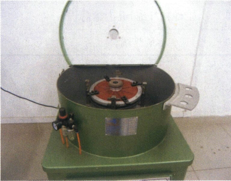
Figure 4-19 Outline of the centrifugal casting machine
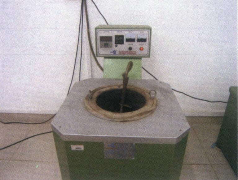
Figure 4-20 Electric furnace outline diagram
① According to the requirements, add the alloy material to the electric furnace, apply electricity to melt it, and maintain the temperature as required.
② Prepare the rubber mold by dusting talcum powder on both sides, then tapping the two halves of the mold to remove excess talcum powder.
③ Preheat the rubber mold. Pour the molten metal into the mold and hold it for a period of time to preheat the mold to a sufficient temperature. Casting can also begin, and after a few times, the mold temperature will increase.
④ In accordance with the rotation direction on the rubber mold, pressure settings, and other markings, the rubber mold installed in the centrifuge, set the parameters to ensure that the air pressure is appropriate in the opposite direction to lock the rubber mold (Figure 4-21).
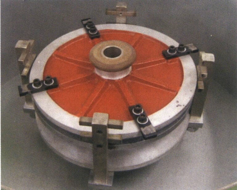
Table 4-10 Casting Pressure Required for Different Types of Workpieces
| Workpiece size | Pressure/MPa | Rotational speed/(r・min-1 ) | Metal temperature | Rotation time/min |
|---|---|---|---|---|
| Large items (above 3100g) | 3. 92 | 250 | Coldest end | 4 ~ 5 |
| Medium item (620 ~ 1 240g) | 3.92 | 400 ~ 475 | The thinner the workpiece, the higher the temperature | 2 ~ 3 |
| Small item (155 ~ 620g) | 1.96 | 475 ~ 550 | Hottest end | 1 ~ 2 |
⑤ Properly close the centrifuge lid and check if the speed setting is correct. When the machine lid is closed, the casting cycle will start automatically. Use an appropriate ladle to push the dross on the surface of the molten metal aside with the back of the ladle and scoop an appropriate amount of molten metal from the furnace.
⑥ Pour the molten metal steadily into the mold (Figure 4-22). The pouring method depends on the type of workpiece and the foundry worker’s skills. The amount of molten metal should be appropriate; too much will splash out of the mold into the casting chamber, while too little will result in incomplete mold filling.
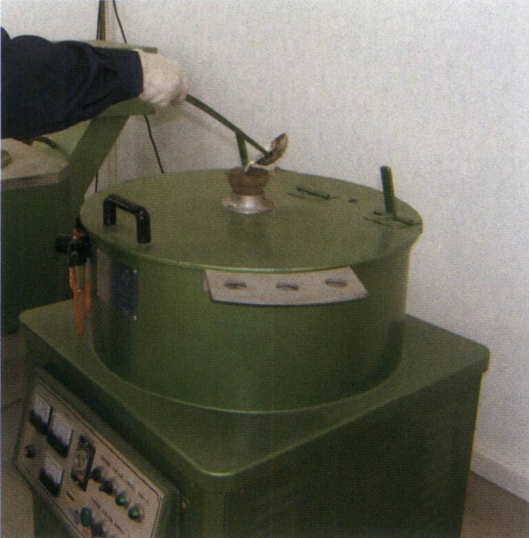
⑦ Pour the remaining metal liquid in the ladle back into the furnace, place the ladle on the edge of the furnace, and wait for the centrifuge to finish spinning.
⑧ After the rotation stops, open the centrifuge cover, remove the upper cover of the mold, then take out the mold and remove the workpiece from the mold. It will be easier to take it out while it’s still hot and then remove the pouring system.
There are several important considerations in centrifugal casting.
① In smelting operations, recycled materials are generally used and returned to the furnace with a new-to-old material ratio of 50:50. When necessary, flux is used to collect slag; when the material is a high-tin alloy, flux is rarely needed, as a high tin content does not produce much slag.
Most foundry workers mix 50% new and 50% recycled materials in a ratio of to. Alloys with high tin content do not require flux, but it is recommended to use flux to regularly clean the melting pot (clean before adding the sprue and new materials when using 25% the liquid in the melting pot ). The flux will produce metal oxides, forming slag that separates from the molten metal and creates a slag surface on the molten metal. The slag on the liquid surface can be removed with tools. Flux is generally ammonium chloride, added to the melting pot at a ratio of 1 spoon for 25% of the pot, placed in a bell jar, and pressed to the bottom of the melting pot, allowing the flux to disperse from the bottom to various parts of the molten metal.
② Controlling key parameters, such as mold temperature, metal liquid temperature, and rotation speed, is important during the casting process.
a. Maintain the pouring temperature of the molten metal in the furnace; the suitable pouring temperature should be as low as possible while ensuring filling. Practical experience shows that a pouring temperature 10℃ above the liquidus point can achieve good casting results.
b. Ensure that the temperature of the rubber mold is maintained at an optimal value. Experienced foundry workers will preheat the rubber mold to a sufficient temperature at a certain rhythm to achieve good casting results. Still, they will not allow the mold temperature to be too low or too high. When the mold temperature is too high, the lifespan of the rubber mold is shortened.
c. The integrity of the casting is greatly related to the centrifugal speed, ensuring that the speed during casting corresponds to the workpiece. When the diameter of the rubber mold is fixed, increasing the speed can allow the molten metal to enter the cavity quickly. However, if the speed is too high, it can easily cause a flash on the casting or vibrations during rotation. Conversely, if the casting speed is too low, the molten metal may solidify in the runner before filling the cavity, leading to an incomplete shape of the casting (Figure 4-23). Old centrifuges do not have instruments to display the speed, while new centrifuges generally have speed display gauges, but they need to be calibrated regularly. Different machines can significantly differ in actual values even if set to the same speed.
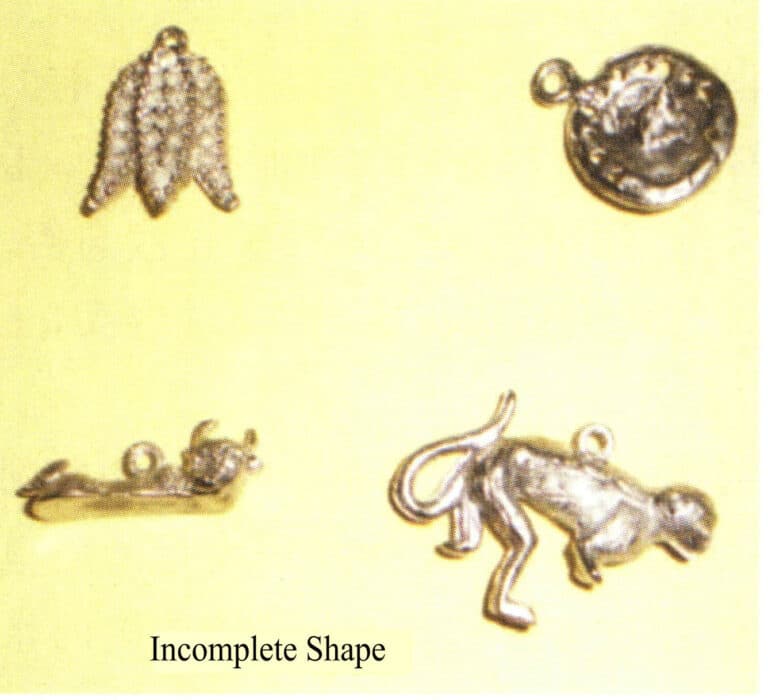
③ Set the appropriate air pressure; too high pressure will deform the workpiece, while too low pressure will cause a flash on the workpiece. High pressure should only be used when necessary.
④ Before casting, apply an appropriate amount of talcum powder to the rubber mold. The talcum powder should be very fine. The purpose of applying talcum powder is to prevent the workpiece from sticking to the mold, facilitate gas discharge from the cavity, and help the flow and filling of the molten metal.
(6) Trimming Assembly
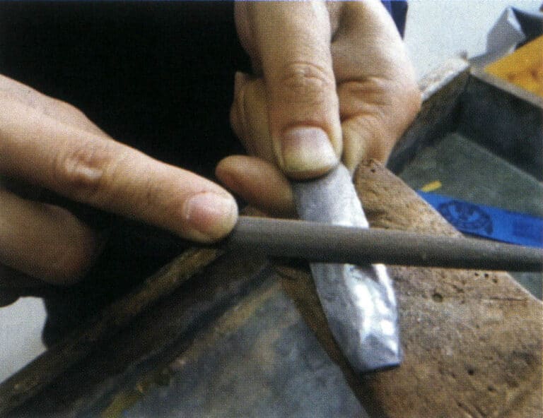
After casting, the casting is connected to the pouring system, and the castings have various burrs that must be cleaned through processes such as removing the sprues and trimming. The tools used in this process are relatively simple, generally including scissors, blades, files, sandpaper, and electric hanging flexible shaft grinder (Figure 4-24).
For accessories such as chains and hairpins, after the accessory blanks are processed, it is necessary to assemble and weld fixed parts such as springs and shafts, which is also an important link in combining the decorative and functional aspects of the accessories.
(7) Polishing
The jewelry blanks that have been trimmed and welded, although the large burrs have been cleaned up, still do not meet the surface brightness requirements of the craftsmanship and must undergo polishing vibration to remove surface sand holes. There are many polishing methods, including manual and mechanical polishing, which should be selected based on the characteristics of the workpiece and equipment conditions. Low melting point alloys are relatively soft and have low melting points, so special care must be taken during polishing to avoid overheating. The speed of the manual grinding motor should be adjustable, and the speed of a single motor should generally not exceed 1750r/pm, and it should avoid staying too long in one place polishing.
① Polishing equipment. During mass production, mechanical polishing can be used, and the method of batch polishing should be determined based on the workpiece’s material and the surface quality requirements. Remember that the polishing time is very short for low melting point alloy workpieces, and the operation process must be strictly controlled to prevent excessive polishing. The polishing worker should understand the characteristics of the metal material of the jewelry; the higher the tin content, the harder the metal, which generally makes it easier to polish. Additionally, it is important to be clear about the quality requirements of the workpiece, whether it needs surface electroplating or to retain the original metal color.
In actual production processes, several typical batch polishing equipment are characterized as follows:
- Vibrating polishing machine. It can use various materials for wet grinding or dry polishing and for polishing treatment before electroplating. Ceramic, plastic, and other abrasives are generally used for wet grinding, and the grinding performance of different abrasives varies. For dry polishing, wooden abrasives such as wood chips, corn kernels, sawdust, etc., are generally used, depending on the situation, to determine whether to add polishing liquid. During operation, care should be taken to avoid temperature rise; the workpiece’s resistance to temperature is inversely proportional to the lead content, meaning the higher the lead content, the poorer the heat resistance of the workpiece.
- Centrifugal polishing machine. This type of equipment has high polishing efficiency. For rough castings, abrasive materials with strong grinding force can be used, along with suitable polishing liquids. During polishing, pre-plating polishing media is used, and a large amount of soapy water is rinsed, which can make the workpiece surface brighter. Sometimes, more soapy water can be added, and a slower water flow can further improve the effect of the polishing media and compounds, which can be prioritized.
- Centrifugal vibration polishing machine. This equipment is rarely used on low melting point alloys because it is prone to heating during polishing. Wet polishing can be used, but over-polishing can easily occur due to its high polishing capability. Additionally, the relationship between loading and unloading time and processing time should be considered comprehensively.
When using the above polishing machine, it is best to equip it with a speed control device to adjust the speed according to the metal’s hardness.
② Polishing media. There are many polishing media available for polishing low melting point alloys. The shape of the media can be tubular, cylindrical, conical, or irregular quadrilateral, depending on which areas require the most work and which need little processing. Commonly used polishing media mainly include wood shavings, wood chips, wooden beads, corn kernels, walnut shells, and other wood-based media. These media types sometimes require a small amount of polishing liquid during polishing; synthetic media are used for alloys with low tin content or lower hardness; plastic media are used for alloys with high tin content. During use, the level of the media and processing time can be adjusted; the harder the metal (i.e., the higher the tin content), the faster the wear rate of the media.
A large amount of polishing generates suspended particles, requiring enhanced filtration. Attention should be paid to the monitoring and discharge of industrial wastewater. Due to lead, cadmium, and other harmful elements in low-melting-point alloys, the polishing waste liquid must be tested and treated to ensure compliance with local discharge standards.
Figures 4-25 and 4-26 are the defective tin alloy jewelryblanks and lead alloy jewelry blanks after mechanical polishing, respectively.
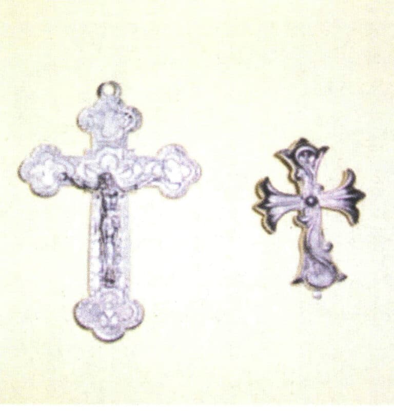
Figure 4-25 Tin alloy jewelry blanks after mechanical polishing

Figure 4-26 Lead alloy ornament blanks after mechanical polishing
(8) Electroplating
Lead-tin alloy is a gray material, and the dazzling imitation jewelry we see is treated with electroplating. Electroplating can be divided into hanging plating and rolling plating based on the process method; in terms of the effects of electroplating, there are gold plating, silver plating, copper plating, nickel plating, white steel plating, and some other special electroplating effects.
Like the electroplating of jewelry made from other materials in the jewelry industry, the type of metal and surface condition significantly impacts the electroplating effect. Due to the relatively low surface quality of low-melting-point alloy jewelry after casting, it is often pre-plated with copper and nickel before electroplating with gold, silver, and other precious metals. The process can also use a conversion coating technique for antiquing. The process steps are as follows:
The workpiece is pulse-plated in a cyanide copper solution, usually for 35-40 seconds, with the time changing according to the voltage. It is necessary to prevent burning at the tip of the workpiece→ after soaking in the thick solution, rinse the workpiece twice→ ultrasonic cleaning of the workpiece→ rinse the workpiece twice→ the workpiece is immersed in an acid or salt solution→ rinse twice→ the nickel plating time depends on the structure of the workpiece, usually for 15-30 minutes. If brightness is required, use a plating solution with a brightener→ rinse twice.
After the above processing, the workpiece can undergo the final electroplating treatment, such as plating with 24K gold, bronze, or silver. Bronze electroplating can be plated for 15 minutes in a commercial bronze plating solution (ammonium polysulfide). Low voltage is used for large pieces, and the electroplating time is appropriately extended, followed by anodizing to turn the surface brown, then rinsing and drying to achieve the required brightness. Metal antiquing treatment usually involves treating the metal to a brown color and then oxidizing it to black. If silver plating is required, it is generally first pulse-plated with silver and then electroplated in a silver cyanide solution. When the workpiece needs to be blackened, it should be plated with thick silver. The blackening treatment after silver plating is generally done using a sulfide method, followed by thorough rinsing.
(9) Effect Production
The electroplated accessories, some of which can be directly packaged and stored, but some also need to have various effects applied according to design requirements, such as release agent applying (burnout and thin coating), spray painting, frosted, dripping oil, and sand flushing (Figure 4-27); after completing these effects, if the product does not require diamond setting, then it can be stored.
(10) Diamond Setting
This is the final step in the process, and the rhinestones are attached using a special adhesive, which can be combined to create various effects of colored rhinestones according to design requirements (Figure 4-28).
(11) Packaging Storage
Products that have passed quality inspection can be packaged and put on the market.

Figure 4-27 Alloy jewelry with surface spray paint
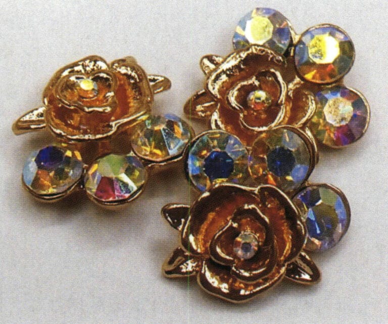
Figure 4-28 Diamonds setting jewelry
2. Cold Extrusion Forming Process
Cold extrusion technology is an advanced production process that is high precision, efficient, high quality, and low consumption. It is suitable for the mass production of medium—and small-sized parts. Compared with conventional processes, it can save 30%-50% materials and 40%-80% energy and produce high-quality products. Dimensional accuracy is good, and it can process complex shapes that are difficult to machine.
In the past, tin crafts were mainly shaped and cast by hand, and these methods have limitations. For example, the development cycle is long, manufacturing time is lengthy, and surface quality is poor. Tin has good ductility and plasticity, with material properties second only to gold and silver, and higher ductility and plasticity than black and non-ferrous metals. These characteristics allow it to be shaped using cold extrusion processes.
The cold extrusion forming process involves melting tin casting material→ materials casting→ materials placing→ pre-forming→ lubrication treatment→ extrusion forming→ removing residual materials→ trimming and polishing. During pre-forming, the material can be extruded or machined as required. Generally, cold extrusion forming is fast and can ensure accurate extrusion dimensions.
3. Die Casting Process
Pressure die casting refers to the process of injecting molten metal into a mold under the action of external forces (excluding gravity). In a broad sense, pressure die casting includes pressure die casting with a die-casting machine, vacuum casting, low-pressure casting, centrifugal casting, etc.; in a narrow sense, die casting specifically refers to the metal die casting of a die casting machine, abbreviated as die casting.
The essence of die casting is a method in which liquid or semi-liquid metal is filled into the die cavity at high speed and formed and solidified under pressure to obtain castings. Die casting is one of the most advanced metal forming methods and is an effective way to achieve minimal or no chips. It has wide applications and rapid development. Die casting has become one of the important production processes for zinc alloy jewelry.
3.1 Characteristics of Die Casting
Die casting has two main characteristics: high pressure and high-speed filling. The commonly used injection pressure ranges from several thousand to tens of thousands of kPa and can even reach 2×10⁵KPa.The filling speed is about 10-50m/s, and sometimes can even exceed 100m/s. The filling time is very short, generally within the range of 0.01-0.2s.
(1) Edut
Compared with other casting methods, die casting has the following three advantages.
① The product quality is good. The dimensional accuracy of the castings is high, generally equivalent to 6-7 grade, and can even reach grade 4; the surface finish is good, generally equivalent to 5-8 grade; the strength and hardness are relatively high, with 25%-30% strength generally improved compared to sand casting, but the elongation rate decreases by about 70%; the dimensions are stable, and interchangeability is good; thin-walled complex castings can be die-cast. For example, the minimum wall thickness of current zinc alloy die-castings can reach 0.3 mm; aluminum alloy castings can reach 0.5 mm; the minimum casting hole diameter is 0.7 mm.
② High production efficiency. The machine production rate is high; for example, a typical horizontal cold chamber die casting machine can cast 3000-7000 times in an average of eight hours, while a small hot chamber dies casting machine can cast times in an average of eight hours; die casting molds have a long lifespan, and when using alloys with a lower melting point, a set of die casting molds can last for hundreds of thousands of times or even over a million times; it is easy to achieve mechanization and automation.
③ Good economic benefits. Due to the advantages of precise dimensions and smooth surfaces of die-cast parts, the amount of polishing and finishing work is reduced, improving metal utilization and reducing the large amount of processing equipment and man-hours.
(2) Haitat
Although die-casting has many advantages, some disadvantages need to be addressed.
① During die casting, due to the high speed of liquid metal filling the cavity and the unstable flow state, it inevitably traps air from the cavity inside the casting. Therefore, using the general die casting method, the casting is prone to porosity, cannot undergo heat treatment, and is unsuitable for surface spraying; otherwise, the internal porosity of the casting will expand when heated during the treatments above, causing the casting to deform or bubble.
② It isn’t easy to die-cast complex castings with internal concavities.
③ High melting point alloys (such as copper and black metals) have a lower lifespan in die casting.
④ It is unsuitable for small batch production, mainly because the manufacturing cost of die-casting molds is high, and the production efficiency of die-casting machines is high, making small batch production uneconomical.
3.2 Types of Die-Casting Machines
Die casting is a metal casting process on a die-casting machine, and it is currently the most efficient. Die casting machines are divided into hot chamber and cold chamber machines.
(1) Hot Chamber Die-Casting Machine
The hot chamber die casting machine has its pressure chamber immersed in liquid metal from an insulated melting crucible. The injection components are not directly connected to the machine base but are mounted on the crucible, as shown in Figure 4-29. The advantages of this type of die-casting machine are simple production processes and high efficiency; it consumes less metal and has stable processes. However, the pressure chamber and injection plunger are long-term immersed in liquid metal, which affects their service life and can easily increase the iron content of the alloy. The hot chamber die-casting machine has a high degree of automation, low material loss, and higher production efficiency than that of cold chamber die-casting machines. Still, the production of castings made from low melting point materials such as zinc and magnesium alloys is currently limited due to the constraints of the heat resistance of the machine components.
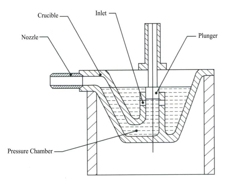
(2) Cold Chamber Die-Casting Machine
The pressure chamber of a cold chamber die-casting machine is separate from the holding furnace. During die casting, liquid metal is taken from the holding furnace and poured into the pressure chamber for casting (Figure 4-30). Due to their higher melting point, the aluminum alloy die castings widely used today can only be produced on cold chamber die casting machines. Cold chamber die-casting machines are divided into two types based on their pressure chamber structure and layout: horizontal die-casting machines and vertical die-casting machines (including fully vertical die-casting machines).
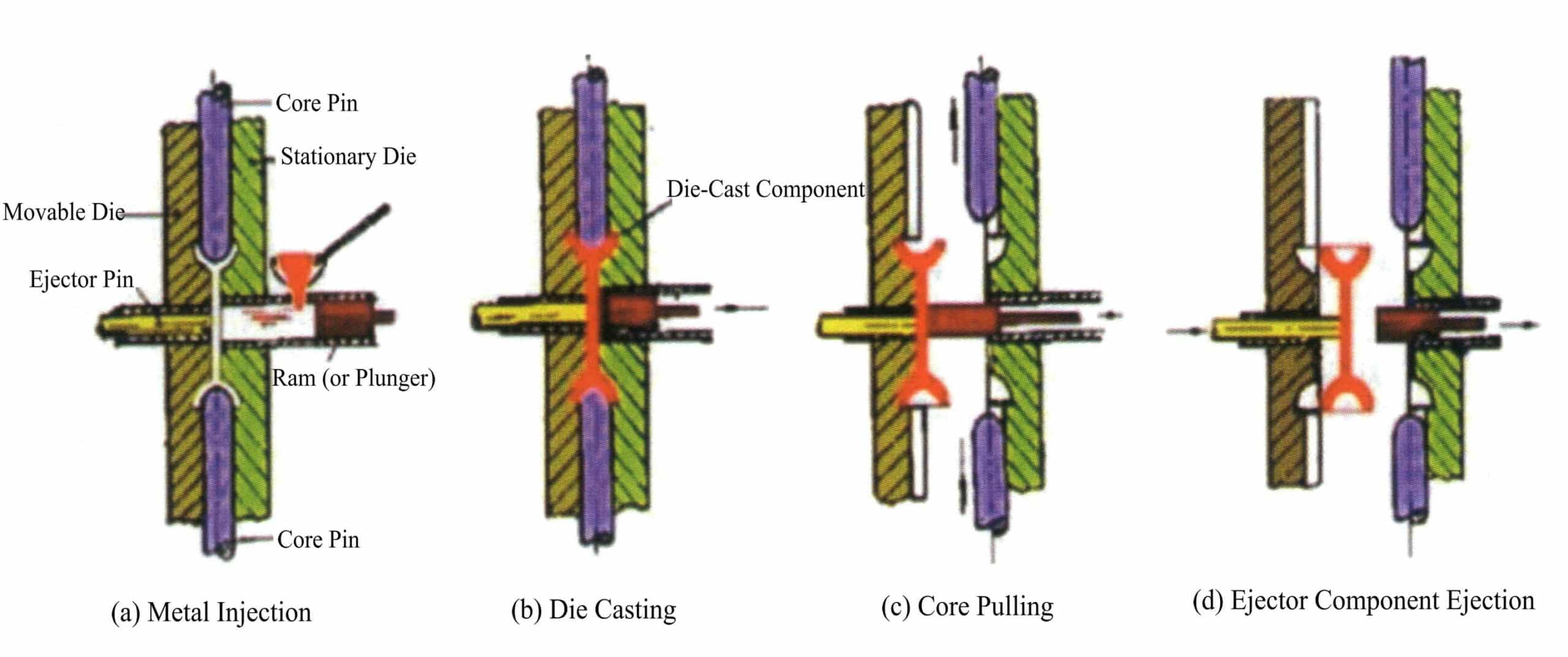
3.3 Selection of Die-Casting Machines
In actual production, not every die-casting machine can meet the needs of die-casting various products, and selection must be made based on specific circumstances, generally considering the following two aspects.
(1) Select according to Different Varieties and Batches
When organizing multi-variety, small-batch production, choosing a die-casting machine with a simple hydraulic system, strong adaptability, and the ability to make quick adjustments is generally necessary. When organizing single-variety, large-scale production, a high-efficiency die-casting machine equipped with various mechanized and automated control devices should be selected; for large-scale production of a single variety of castings, a dedicated die-casting machine can be chosen.
(2) Select according to Product Structure and Process Parameters
The product’s dimensions, weight, wall thickness, and other parameters significantly impact the selection of die-casting machines. The weight of the casting (including the pouring system and overflow trough) should not exceed the rated capacity specified by the die-casting machine. Still, it should not be too small to avoid wasting the machine’s power.
For jewelry, the general size is relatively small, and using a die-casting machine of 10-25t is sufficient to meet production needs.
3.4 Die Casting Process
(1) Basic Process of Die Casting
Taking the vibration force hot chamber die casting machine as an example; its process is as follows.
① Before starting the die casting, first check the oil level in the oil tank, power on the electric furnace to heat it, and insert the thermocouple for temperature measurement; heat the insulation sleeve; preheat the die casting mold according to the process requirements; supply cooling water to the injection support, and supply cooling water to other parts as needed; open the pressure cylinder valve and the air shut-off valve; turn on the pressure gauge switch, start the oil pump, and raise it to the required pressure; after the alloy melts, immerse the injection piston in the molten alloy, then install the injection piston; test the mold opening and closing, and confirm that the mechanism is normal before proceeding with production.
② When working with die casting, safety must be observed. Operators must wear appropriate protective gear and not stand directly in front of the die-casting parting line and nozzle to prevent metal splashes that could cause accidents. When starting die casting, first operate in “manual” mode once to confirm normal operation before switching to “semi-automatic” or “automatic” mode. Regularly check that various instrument readings meet process requirements and that the equipment functions normally. If any abnormalities are found, check by pressing the “emergency stop” button, and only continue working after troubleshooting. Adjust the temperature of the insulation sleeve as required by the process to prevent nozzle blockage and overheating metal splashes. Regularly monitor the temperature rise of the hydraulic oil, which must not exceed 55℃. Adjust the cooling water flow as necessary depending on the degree of rise in temperature. If the equipment is idle for over half an hour, the injection piston must be removed and placed next to the crucible for insulation. If idle for more than one hour, the power must be turned off, and the pressure cylinder valve must be closed to prevent accidental operation and pressure loss in the pressure cylinder. The metal liquid level should always submerge the injection piston, and the maximum liquid level should be 20 mm below the edge of the crucible. When adding metal blocks to the crucible, the size of the blocks should not be too large to avoid significantly lowering the metal temperature, and the blocks should be preheated according to the process. Wet metal blocks are not allowed to prevent explosion accidents.
③ After die casting, leave 2/3 of the molten metal in the crucible; the thermocouple can remain in the crucible, close the liquid pump, cut off the power supply, close the water supply valve, remove the injection piston, and apply a thin layer of machine oil to the equipment’s moving parts (such as the cylinder rod, guide rod, slide rail, etc.).
(2) Die-Casting Process Parameters
① Selection of pressure and speed. Injection pressure selection should be based on different alloys and castings structural characteristics to determine, for zinc alloy jewelry, casting wall thickness <3mm, using the injection pressure of 30 – 40MPa, casting wall thickness >3mm, using the injection pressure of 50 – 60MPa. For the selection of filling speed, generally, for thick-walled castings or those with high internal quality requirements, a lower filling speed and higher boost pressure should be chosen; for thin-walled castings or those with high surface quality requirements, as well as complex castings, a higher pressure and higher filling speed should be selected.
② Pouring temperature. The pouring temperature refers to the average temperature of the liquid metal when it enters the mold cavity from the press head. Since measuring the temperature of the liquid metal in the pressure chamber is inconvenient, it is generally represented by the temperature in the insulation furnace.
If the pouring temperature is too high, it leads to significant shrinkage, making the casting prone to cracks and large grain size, and it can also cause adhesion; if the pouring temperature is too low, it is likely to produce cold shuts, surface patterns, and insufficient pouring defects. Therefore, the pouring temperature should be considered with pressure, die-casting mold temperature, and filling speed.
The melting point of the zinc alloy used for die casting is 382-386℃ and appropriate temperature control are important factors in controlling the composition of the zinc alloy. To ensure good fluidity of the alloy liquid to fill the cavity, the temperature of the metal liquid in the zinc pot of the die-casting machine is 430-450℃. For thin-walled and complex parts, the upper limit of the die-casting temperature can be taken; for thick-walled and simple parts, the lower limit can be taken. The temperature of the metal liquid in the central melting furnace is. The temperature of the metal liquid entering the gooseneck pipe is the same as that in the zinc pot. By controlling the temperature of the metal liquid in the zinc pot, the pouring temperature can be accurately controlled, ensuring that the metal liquid is a clear liquid without oxides; the pouring temperature remains stable.
③ The temperature of the die-casting mold. The die-casting mold should be preheated to a certain temperature before using gas, a torch, electrical appliances, or induction heating.
In continuous production, the temperature of the die-casting mold often rises, especially for high-melting-point alloys, and it rises quickly. Excessively high temperatures not only cause the liquid metal to become viscous but also slow down the cooling of the castings, leading to coarse grains. Therefore, when the temperature of the die-casting mold is too high, certain cooling measures should be taken. Typically, cooling is done using compressed air, water, or chemical media.
④ Filling, holding pressure, and opening time.
a. Filling time. The time required from when the liquid metal starts to enter the mold cavity until it is filled is called filling time. The length of the filling time depends on the size and complexity of the casting. The filling time tends to be relatively longer for large and simple castings, while for complex and thin-walled castings, the filling time is shorter. The filling time is closely related to the inner gate’s cross-sectional area or the inner gate or the width and thickness of the inner gate, which must be correctly determined.
b. Holding pressure and opening time. The duration from when the liquid metal fills the cavity until the inner gate is completely solidified under the continued action of the injection punch is called the holding pressure time. The length of the holding pressure time depends on the material and wall thickness of the casting.
After holding pressure, the mold should be opened to remove the casting. The time from the end of injection to the die’s opening is called the opening time. The opening time should be controlled accurately; if the opening time is too short, the alloy strength is still low, which may cause deformation during the ejection of the casting and the fall of the self-pressing die; but if the opening time is too long, the temperature of the casting will be too low, resulting in significant shrinkage, and there will also be greater resistance to core pulling and ejection of the casting. Generally, the opening time is calculated as 3 seconds for a casting wall thickness of 1 mm and adjusted accordingly after testing.
(3) Coating for Die Casting
In the die-casting process, coatings prevent the casting from welding to the die, reduce the friction resistance during ejection, and avoid excessive die heating. The coating requirements are as follows:
- At high temperatures, it has good lubricity.
- Low boiling point: the diluent can evaporate quickly at 100-150℃.
- No corrosive effect on die-casting molds and die-cast parts.
- The performance is stable, and the diluent should not evaporate too quickly in the air and become thick.
- No harmful gases will be released at high temperatures.
- There will be no dirt accumulation on the die-casting cavity’s surface.
3.5 Casting Cleaning
3.6 Post-processing
Copywrite @ Sobling.Jewelry - Custom korujen valmistaja, OEM ja ODM korut tehdas


