How does Sobling control jewelry molds’ quality?
Jewelry Master Mold Quality Inspection and Defects Analysis
Inledning:
The Jewelry master mold is the first process in the jewelry processing process. The following methods generally make it: first, handmade master mold, that is, through sawing, filing, welding, engraving, etc., to create a sharp-edged, clear-lined, and smooth-surfaced master mold. Second, carve a wax model by hand and then cast it into a master mold. Third, various rapid prototyping methods are used to make wax or resin models, and then they are cast into silver versions or directly made into master molds out of metal. In modern jewelry production, rapid prototyping technology is increasingly used to improve the efficiency of pattern making.
The quality of the jewelry master mold has a significant impact on the production efficiency, production cost, and product quality of jewelry products. A good quality jewelry master mold with a reasonable structure and clean surface can reduce the processing workload of the latter process. On the contrary, a shoddy jewelry master mold can only produce inferior products, because the defects on the jewelry master mold will be faithfully replicated on the product, resulting in a batch of products being scrapped or an increased repair workload. Therefore, the jewelry master mold is to ensure that the jewelry products meet the customer’s quality requirements of the foundation, and must strengthen the master mold quality inspection and test.
Innehållsförteckning
Section I: Master mold quality inspection content
Huvudinnehållet i kvalitetsinspektionen för masterform inkluderar form, storlek, vikt, struktur, ytkvalitet, gjutning av gran etc.
1. Shape
The most essential requirement for a jewelry master mold is to recover original appearance; that is, the production of the master mold must strictly conform to the requirements of the design drawings or the designer’s intentions. To achieve this, the operator must first use three-dimensional thinking to deeply experience and understand the designer’s ideas and themes and also consider the master mold’s integrity, coordination, and aesthetics.
2. Dimension Inspection
Different types of jewelry have both standard size requirements and specific sizes for each kind that need to be considered during the sample making. Taking rings as an example, each part has specific size requirements, as shown in Figure 5-1.
2.1. Rings
Finger Size: Refers to the inner diameter of the ring, generally indicated by finger size number.

Shank Width: Refers to the width of the shank at the bottom of the ring.
Shank Thickness: Refers to the thickness of the shank at the bottom of the ring 0.6-0.7 mm
Setting Mounts Thickness: The thickness of the part without gemstones on the head edge. Measure with a caliper; if the customer does not provide requirements, 0.6-0.7 mm
Prong Thickness: The thickness of the prong setting for gemstones is measured with a caliper. If the customer does not provide requirements, 1-1.2 mm can be used.:1.5-1.8 mm
Stone mounts edge thickness: the thickness of the edge around the stone setting, such as the edge thickness, can be 1.5-1.8 mm.
2.2. Necklace
Overall length: the overall length excluding the clasp connection part. In general, necklaces are commonly 16 to 17 inches, and bracelets are widely 6.5 to 7 inches.
Link length: the length of a single link.
The requirements for the thickness of the body, the thickness of the setting, and the thickness of the stone setting edge are similar to rings.
2.3. Bracelet
Inner Diameter: Refers to the inner diameter of the bracelet, generally expressed in size number.
Width: Refers to the cross-sectional width of the bracelet wall.
The requirements for the thickness of the body, the thickness of the setting, and the thickness of the stone setting are similar to rings.
Tools for inspecting the master mold size include vernier calipers, ring gauges, internal calipers, etc. The master mold size should be determined according to the drawings, but shrinkage and subsequent processing allowances should be reserved. That is, the master mold size=product requires size x (1+ shrinkage rate )+ processing allowance.
Note that the shrinkage rates in different directions are different, and different product structures and materials will also affect the shrinkage rate. The processing allowance should be determined based on the surface quality of the casting; the surface processing method used, and the required degree of surface quality. Generally, take 0.1-0.6 mm unequal. When the casting quality is poor, manual processing is used, and the surface quality requirements are high, the reserved processing allowance should be more significant.
The molded workpiece has good surface density and smoothness, so the reserved machining allowance can be smaller. Therefore, the determination of the master mold size is not fixed and should be determined according to the actual situation.
3. Weight
The master mold weight largely determines the weight of the product. When the master mold material and product material are chosen, there is an approximate proportional relationship between their weights. Therefore, the weight of the product can be controlled by controlling the weight of the master mold.
For handmade silver molds, the weight of silver can be directly determined by the proportion relationship between silver and the product material. For hand-carved wax molds, the weight of the wax molds is generally controlled first. After the wax molds is casted into master molds, the weight of the master molds is controlled by handling the master molds and refining the details. The approximate proportion relationship between wax and metal is as follows:
| Metal Type | 1 gram Wax model = Metal weight after casting |
|---|---|
| Sterling Silver | 10 grams |
| 24K Gold | 20 grams |
| 18K Gold | 15 grams |
| 14K Gold | 14 grams |
| 10K Gold | 10 grams |
4. The Master mold Structure
A reasonably structured master mold can significantly reduce the workload during mass production and reduce the likelihood of quality issues; conversely, when the master mold structure is unreasonable, there is often a situation of half the effort for double the results during mass production. Therefore, careful consideration of subsequent production operations should be made before making the master mold, and the corresponding master mold structure should be designed. The structure of the master mold includes the main body, components, inserts, accessories, process attachments, etc.
4.1 Main body:
Refers to the central part of the master mold.
Components: More complex master molds, such as those with significant manufacturing difficulties, quality assurance challenges, and high production costs, are generally divided into several components for separate production, and these components are then assembled.
4.2 Inserts:
Refers to small accessories embedded in the master mold body. When assembling and fixing the inserts, welding is usually required, and attention should be paid to the welding strength and the amount of welding materials used.
4.3 Setting:
Refers to the base for setting gemstones. There are various types of settings, which should be determined according to the order requirements. The setting’s position, size, stone setting base depth, and the size and length of the claws will all have a significant impact on the setting quality.
4.4 Hinge:
Refers to a mechanical device used to connect two components and allow them to rotate. Hinges are often used in jewelry such as earrings, bracelets, and brooches. The flexibility and durability of chucks directly affect the functionality of jewelry use.
4.5 Ear pin:
Refers to the metal rod that passes through the ear hole on an earring, usually used with an ear clip. The position, length, thickness, etc., of the ear pin should be determined according to the master mold structure.
4.6 Box clasp with the tongue:
Refers to the fastening fittings used at the open connection parts of bracelets, wrist chains, etc., including the tongue(spring piece) and the clasp box used in conjunction with it.
4.7 Craft accessories:
Refers to some accessories that are not present on the finished jewelry but are added due to production process requirements, such as extra sprues, patches, etc. These accessories are generally required to be removed after completing specific production processes.
5. Master mold surface quality
The master mold surface quality has a significant impact on product quality, production efficiency, production cost, etc. Doing extra work on the master mold may bring returns that are difficult to measure in production, but some manufacturers often fail to realize this simple truth. The master mold surface should be smooth and delicate, without noticeable sand eyes, holes, scratches, or uneven edges.
6. Casting sprue
The casting sprue is reserved as a channel for the flow of molten metal in the casting process. In jewelry casting, the correct setting of casting sprue is an essential condition to ensure casting quality. Unreasonable casting sprue settings, such as insufficient filling, shrinkage, and porosity, directly or indirectly cause many common defects in investment casting. The rationality of casting sprue setting is mainly evaluated from aspects such as the position, quantity, shape, size, and connection method of casting sprue.
(1). When making the master mold, the casting sprue should be regarded as an integral part of the master mold and welded to the master mold with high solder. Such casting sprues are beneficial for the filling of wax or molten metal. If there is no casting sprue on the master mold and it is randomly dug out on the rubber mold with a scalpel, such a channel is prone to turbulence, which is not conducive to filling.
(2). The casting sprue should be connected to the thickest part of the casting, and the equivalent thickness of its section should be greater than that of the casting. Because the casting sprue bears the function of compensating for shrinkage, its solidification time should be later than that of the casting to avoid defects such as shrinkage and shrinkage holes in the casting. The connection method between the casting sprue and the workpiece also has a significant impact on the quality of the casting. A right-angle connection or necking at the connection point is not conducive to the filling of molten metal and may cause turbulence. A rounded corner should be poured out at the root of the casting sprue where it connects to the casting, and the radius of the corner should be controlled. It is necessary to avoid corners that are too small to be effective and corners that are too large to increase cleaning difficulty.
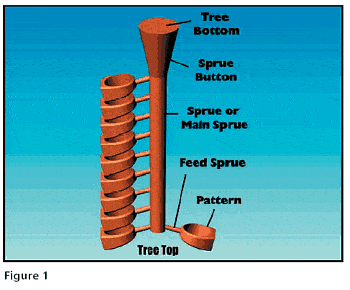
(3). The length of the sprue must be reasonable. The process of wax or metal liquid flowing through the sprue channel is a gradual cooling process. If the sprue is shorter, it is conducive to filling and may lead to filling defects. However, the sprue length is too short, causing the workpiece to be too close to the core. In that case, it not only reduces the number of workpieces of a single cast metal but also increases the possibility of shrinkage defects due to excessive heating of the workpiece.
(4). The number of sprues should be determined according to the structure of the workpiece. Under the premise of meeting filling and feeding requirements, reducing the number of sprues can reduce the workload of grinding and cleaning and improve the yield of the process; however, if the workpiece is relatively thin and complex or large, when more than a single sprue is needed to meet the requirements, two or more sprues should be used.
(5). The shape of the casting sprue. The cross-sectional shapes of casting sprues commonly seen in production include circular, square, triangular, etc. It is recommended to use a circular cross-section first, as it not only facilitates the smooth flow of molten metal but also reduces heat loss, prolonging the time needed to maintain the channel and hold the shrinkage channel. Casting sprues come in various forms, such as single branch, Y-shaped, V-shaped, hook-shaped, circular, etc., and the selection should be made according to the actual state of the workpiece.
Section II. Quality Inspection Personnel and Methods
Compared with quality inspectors in other processes of jewelry making, the requirements and difficulty of master mold quality inspectors are much higher. They are commonly referred to as pattern viewers or pattern inspectors in the industry. An excellent pattern viewer is required to understand the design of jewelry, even if not a designer by profession, but should have a clear understanding of the designer’s work and be able to understand 3D design drawings. They should have rich experience in master mold making and be proficient in silver master mold structure, silver master mold production processes, and quality requirements. Familiar with the operation process of the master mold-making department, familiar with the production and processing links of jewelry making, have long-term practical experience in factories, have a thorough understanding of processes and production flow, have a particular knowledge of jewelry materials, and have the ability to predict abnormal production issues.
For today’s jewelry production methods, several key factors affect the quality of the master mold.
One is the review of CAD drawings, where issues related to the master mold shape, size, structure, and jewelry production process should be carefully considered when drawing CAD drawings. However, many CAD drafters are not familiar with production processes, so not only do designers need to review CAD drawings to grasp aesthetics and shapes, but reviewers also need to conduct structural and process reviews and provide modification suggestions and requirements.
Second, it is necessary to inspect the rapid prototyping wax or resin models to check if they are intact or have defects such as missing parts, deformations, sand holes, etc. When such defects are found, repairs should be made before arranging for silver casting. If repairs are not possible, new wax or resin models should be made. Hand-carved wax models should also be carefully inspected.
Third, inspections should be carried out on replicated silver models, checking whether the silver models are intact or have severe defects and conducting inspections on shapes, structures, assemblies, dimensions, processes, surface quality, etc.
The means of inspecting the master mold are relatively simple. The external shape, structure, charm, etc., mainly rely on visual observation. Dimension inspection can be done using a ring gauge, caliper, inner caliper, etc. Surface quality can be checked with the naked eye and magnifying glass.
Section III. Common defects of the master mold
7. Shape inconsistency
Jewelry master molds generally have design drawings, sketches, or customer oral requirements for the shape. After the master mold is completed, it should be checked against the drawings or confirmed by the customer.
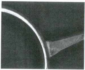
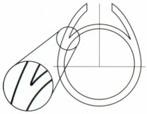
【Case 5-1】The inner edge of the ring requires an inner arc, as shown in Figure 5-2.
Analys:
Jewelry should consider wearing comfort. The inner edge of the ring usually requires a rounded corner, but often, it is made into a straight edge during production.
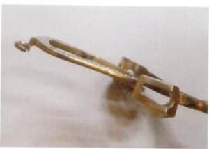
【Case 5-2】Deformation, as shown in Figure 5-3.
Analys:
Deformation issues with the master mold often occur in production, including the jewelry structure, which is generally delicate and has a weak ability to withstand external forces. The material of the master mold, usually made of 925 silver, is also a factor. Compared to other commonly used materials in jewelry, such as K gold, copper alloys, etc., silver alloys have lower strength and hardness, leading to the deformation of the master mold during the production process, especially during the compression molding process.
Solutions:
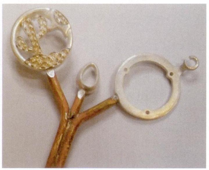
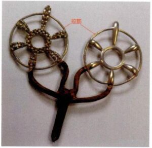
There are several solutions to the master mold deformation problem. First, make necessary adjustments to the master mold structure to avoid being too delicate or having too large a flat surface; second, set up process pull rods, as shown in Figure 5-4, to connect various isolated operating handles with pull rods, significantly reducing the probability of operating rod deformation; third, choose materials with better performance to make the silver version. In recent years, some manufacturers in the industry have made beneficial attempts to develop high-hardness silver alloys, significantly improving the strength and hardness of the alloy by adding trace alloy elements and refining the manufacturing process.
[Case 5-3] The master mold lacks charm, as shown in Figure 5-5.
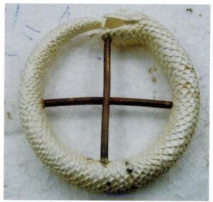
Analys:
A piece of goods should not only have a physical form but also a charm; otherwise, it will need more vivid vitality, especially for some styles of figures and animals. However, it is not easy to grasp the charm in the master mold production. It requires considerable artistic skills. Many times, it can only be understood and not explained in words.
Solutions:
For master mold animal designs, using computer drawing for rapid prototyping often appears mechanical and stiff. It is advisable to prioritize manual wax carving or use computer drawing to create the primary body model and then process it manually.
[Case 5-4 ] The inlay edge on the master mold is not rounded, as shown in Figure 5-6.
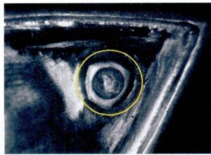
Analys:
Improper technique during sanding has turned the inlay edge on the master mold into a polygon, failing to meet the requirement for rounding.
[Case 5-5 ] The edge of the hole on the master mold is broken and missing, as shown in Figure 5-7.
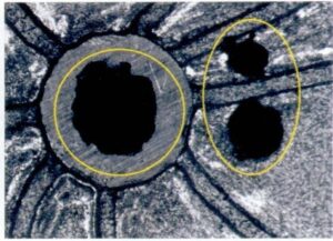
Analys:
In this example, after casting, all three circular holes showed noticeable collapse edges, resulting in severe deformation of the circular holes. The reason for the collapse edge is closely related to the quality of the mold and the casting process during casting, for specific reasons.
8. Dimensional Inconsistency
Jewelry does not have the exact strict requirements for dimensions as mechanical parts, but when it comes to wearing, setting, and assembly, such as ring size, bracelet opening size, bracelet length, coordination between necklace and pendant bail rings, and coordination between inlay and base, accurate dimensions of the master mold are required.
【Case 5-6】The size of the pendant bail does not match.
Analys:
The pendant bail of the pendant has various specifications. Its size is generally determined based on the shape size, structure, and material of the pendant and the size of the matching chain. The size of the hole through which the pendant bail is threaded should ensure that the chain passes smoothly. Otherwise, there may be wearing issues.
【Case 5-7】The length of the bracelet does not meet the requirements of the drawing.
Analys:
The length of the bracelet is an essential indicator of its wearing comfort. The size of each link must be determined based on the number of links and the total length of the bracelet required by the drawing, combined with shrinkage and processing allowances. The drawings of jewelry products are often less standardized than those in the mechanical processing industry. It is expected that the drawing will be marked or changed arbitrarily. The size and structural requirements of the bracelet in Figure 5-8 are typical examples. Therefore, when making the master mold, it is necessary to read the requirements of the drawing carefully. If there are any doubts, promptly inquire with the customer to confirm, and not handle it based solely on one’s own understanding.
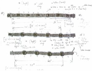
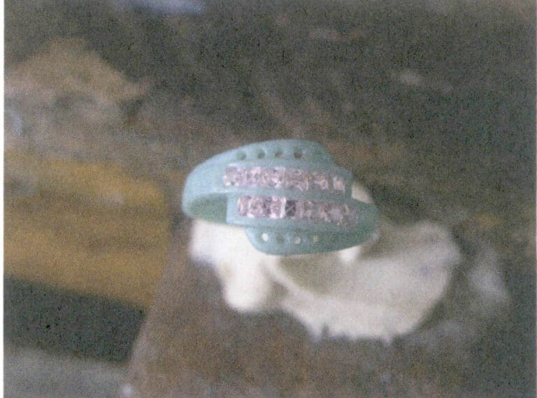
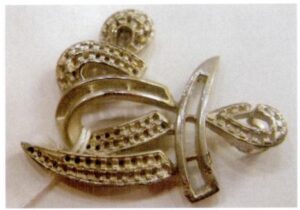
[Case 5-8] The setting size does not match the gemstone, as shown in Figure 5-9.
Analys:
The ladder-shaped diamonds are a commonly used setting method in diamond jewelry. Generally, multiple diamonds need to be arranged in a setting, requiring the diamonds to be arranged closely, smoothly, and seamlessly, with no apparent gaps between diamonds or between diamonds and the ends of the setting. However, if the size is not accurately controlled during the production of the master mold, there may be a problem of mismatched sizes between the setting and the diamonds.
[Case 5-9] The base setting size does not match the accessories, as shown in Figure 5-10.

Analys:
In the ring shown in Figure 5-10, the white part is agate, assembled with the metal base setting and setting, requiring a good fit of the joint surface without apparent gaps. This requirement seems simple, but it takes work to ensure in actual production. When making the silver master mold, it is necessary to accurately grasp the actual shrinkage of the metal base setting and setting, which needs to be adjusted and confirmed through experiments.
[Case 5-10] The size of the prongs in the master mold is too small, as shown in Figure 5-11.

Analys:
In the inlay jewelry, sometimes, to pursue a better inlay effect, the inlay prongs are not made when making the computer wax model (or resin model), but after pouring the silver mold, the prongs are made by hand on the silver mold. The inlay prongs for fixing gemstones must ensure a minimum thickness and height, and the shrinkage of the mold, subsequent processing losses, and other factors should be considered when hand-making the prongs on the silver mold; otherwise, when using this master mold for mass production, after operations such as sanding, prongs polishing, and grinding, some prongs may be too weak and prone to stone loss.
9. The master mold weight does not match
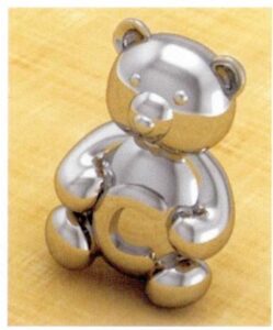
[Case 5-11] Master mold weight is too heavy, as shown in Figure 5-12.
Analys:
For precious metal jewelry, considering cost and market acceptance, it is necessary to control the weight of metal. This needs to be ensured from the mold-making stage to meet the jewelry’s external dimensions and structural strength by hollowing out hidden parts, such as the back and concave areas, as much as possible to reduce product weight. In this case, if only a three-dimensional effect on the front is required, the molds can be made only half, hollowing out the back. If a three-dimensional round carving effect is needed, the master mold design can be made into two parts for the front and back, with the insides of both parts hollowed out. The back can be made into a caged back to significantly reduce weight.
10. The structure of the master mold is unreasonable
The master mold structure has a significant impact on the quality control of subsequent processes. The unreasonable design of the master mold easily causes defects and increases production difficulty and processing workload. The master mold structure design should ensure that the product meets the customer’s dimensional requirements and fully considers the operability of the production process. Here are some common examples of unreasonable master mold structures.
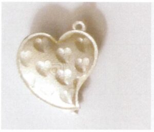
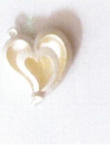
[Case 5-12] The master mold is not disassembled, and the internal parts cannot be sanded, as shown in Figure 5-13.
Analys:
The main body of the earrings, in this case, is heart-shaped. To reduce weight, small heart-shaped hollows are cut out on both sides of the heart shape, and the inside of the heart shape is hollowed out. However, during the CAD drawing, the operability of the holding molds and the mold during production was not fully considered, resulting in the entire heart shape being formed, making it impossible for the replicated silver mold to handle the hollowed interior cavity. Subsequent rubber mold and product finish are, of course, difficult.
Solutions:
Separate the heart shape into two halves and wax them separately. Set positioning protrusions and grooves on the joint surface, as shown in Figure 5-14. After the two halves of the silver mold are appropriately sanded, assemble them for mold making & correctness, and then make the rubber mold separately.
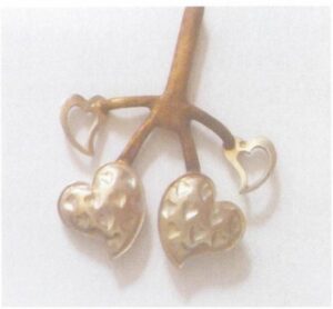
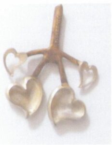
[Case 5-13] The master mold inlay holes in the master mold are small and deep, as shown in Figure 5-15.

Analys:
This kind of inlay hole structure is not conducive to production or the optical effect of diamonds. Because the small and deep inlay holes are not easy to smooth during casting and even often get blocked, it is challenging to perform mold making and polishing properly, and it is not easy to molds during electroplating, making the diamonds look dark. Sometimes, it is necessary to manually press the bottom of the stone to make it shiny, which could be more efficient and effective.
Solutions:
Various cutting and grinding styles of gemstones have corresponding thicknesses. When making molds, the relationship between the diameter and depth of the inlay holes should be considered. Gemstone inlays should be both stable and have a good luster, so the size of the inlay holes should be set reasonably. Since the stability of gemstones depends only on the setting base position and the wrapping of the metal edge, the gemstone below the girdle does not touch the inlay hole wall.
In principle, as long as the depth of the setting hole slightly exceeds the thickness of the gemstone. Therefore, the setting stone part can be thinned by hollowing out the bottom, as shown in Figure 5-16.

[Case 5-14] The master mold hollow part is too slender, as shown in Figure 5-17.

Analys:
Jewelry pieces often have a hollow structure. If the hollow part is designed to be too slender, the delicate part of the rubber mold will hang down, causing swinging during wax injection, leading to defects such as misalignment and flash. During wax injection, the delicate part of the rubber mold may also tear off, or the delicate gypsum may break off during the making of the plaster mold, resulting in the disappearance of the slender hole in the workpiece.
Solutions:
The hollow part in the master mold should be considered in combination with the production process on the premise of meeting the design requirements. In this example, the hollow part is on the inner wall, aiming to reduce weight without affecting the appearance. Therefore, when making the molds, the hollow part should be set as an easily machinable arc, and the two corresponding hollow positions should be separated, as shown in Figure 5-18. In addition, while meeting the inlay size requirements, the bottom of the annular inlay should be appropriately removed to reduce the depth of the hollow part.

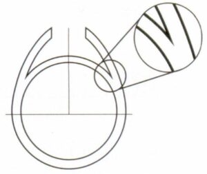
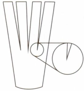
[Case 5-15] The master mold has sharp angles at the connecting parts or recessed decorations, as shown in Figure 5 -19.
Analys:
This sharp angle connection will cause several problems: the rubber mold is prone to tearing during production, resulting in uneven edges in the final product; the fragile gypsum is prone to breakage when making the plaster mold; during casting, the metal liquid is prone to turbulence. Causes defects such as pores and inclusions in the workpiece; it is difficult to polish the sharp corner, and when mechanical polishing is used, these areas are easily embedded with polishing media; if the casting sprue point is improperly positioned, the workpiece is prone to metal withering.
Solutions:
Modify the sharp corner to a rounded corner, as shown in Figure 5-20, and determine the size of the rounded corner according to the design requirements.
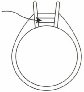
[Case 5-16] The master mold has a narrow opening in the side wall, as shown in Figure 5-21.
Analys:
In addition to hollowing out the bottom of the jewelry in the master mold, a layer is generally opened on the side walls of those with higher side walls. In this case, the claw setting of the main stone also has a layer opened on the side wall of the setting, which is not only to reduce weight but also to improve the brilliance of the gemstone.
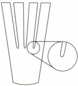
However, when the opening of the layer is narrow, it is not conducive to the positioning of the wax injection mold during wax injection, leading to deformation of the opening of the layer, and it is also not conducive to removing the wax model from the rubber mold.
It is also not conducive to removing the wax model from the rubber mold when the opening of the layer is narrow.
Solutions:
Properly widen the interlayer opening, as shown in Figure 5-22.
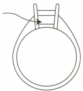
[Case 5-17] The pendant’s hanging part is not smooth in moving, as shown in Figure 5-23.
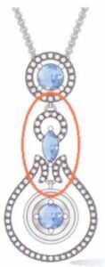
Analys:
In this case, each connecting part of the pendant is connected by a jump ring, requiring each pendant part to swing smoothly. However, during mold making, due to insufficient space between the connecting jump rings, the swinging is easily hindered.
Solutions:
Increase the gap at the connection part appropriately while meeting the design aesthetics, ensuring sufficient clearance between mating parts for adequate movement allowance.
[Case 5-18] The master mold wall thickness varies greatly, as shown in Figure 5-24.
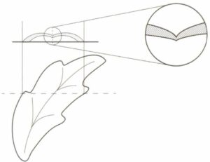
Analys:
In this case, the leaf-shaped workpiece has the thinnest leaf veins in the middle, and the leaf petals are thicker on both sides, with the thickness increasing as it moves away from the central leaf vein. During casting, the thin part will obstruct the feeding channel, leading to shrinkage of porosity in the thick wall area and deteriorating the surface quality. Sometimes, when the wall thickness at the thin part is too small, it may crack due to insufficient strength.
Solutions:
When designing the master mold structure, try to avoid the thick-thin-thick structure. The thin part should have a bare thickness, and the thick part can be hollowed out by adding a ridge to the back and digging out the bottom to reduce the difference in wall thickness between various parts.
[Case 5-19] The master mold stone inlay hole was not drilled through, as shown in Figure 5-25.
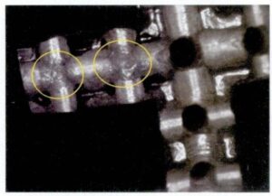
Analys:
For the parts that need to be inlaid with stones, the stone inlay holes should be drilled on the master mold to ensure the consistency of inlay quality during mass production, reduce the loss of precious metals, improve production efficiency, and avoid missing inlays in products. This issue should be paid more attention to in dense inlays of multiple small gemstones.
【Case 5-20】The pearl cap diameter is too small, as shown in Figure 5-26.
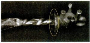
Analys:
The general method of setting pearls is to drill holes in the pearls, apply glue to the metal pin and pearl protrusion, then insert the pin into the pearl hole, and wait for the glue to harden and fix. The size of the pearl protrusion should be appropriate, covering the pearl hole without being too large to cause a disproportionate ratio. In this case, the diameter of the pearl protrusion is too small, making it easy for the glue to overflow onto the pearl protrusion, increasing the cleaning workload and the risk of scratching the pearl.
11. Poor Master mold Surface Quality
The master mold surface quality determines the product’s surface quality, and the master mold must achieve a smooth and clean surface to reduce the workload of polishing and repairing in subsequent processes. Common defects in master mold surface quality are as follows.
【Case 5-21】Welding scars appear at the master mold welding site, as shown in Figure 5-27.
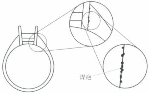
Analys:
In this example, the claw setting of the ring is welded together with the ring band, resulting in many unclean weld scars at the welding site. When the master mold is used for production, the weld scars will transfer to each workpiece, leading to a significant amount of rework. In other words, this defect is replicated in large quantities.
Solutions:
Careful handling of the welding site is required, using appropriate tools to polish it smoothly and brightly.
[Case 5-22] Scratches on the master mold surface, as shown in Figure 5-28.
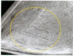
Analys:
Casting the master mold requires processes such as filing, sanding, and making casting sprue to obtain a smooth surface. If the pre-process treatment is too heavy during the molds-making process, it will cause deep scratches that are difficult to remove in subsequent processes or require changing the shape of the molds to remove them.
Solutions:
When making the molds, follow a surface treatment process from coarse to OK, choose the appropriate tools for each process, master the operation force, and the subsequent process should reprocess the entire surface of the previous process.
[Case 5-23] Master mold missed sanding at the inlay, as shown in Figure 5-29.
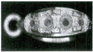
Analys:
In this case, the inlay of the master mold leaked, still retaining the rough and uneven casting surface.
[Case 5-24] There are sand holes on the master mold surface, as shown in Figure 5-30.
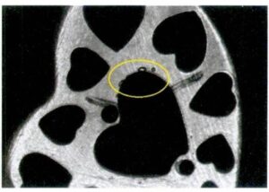
Analys:
In the casting process, many factors of the master mold will lead to sand hole defects, including the casting process, mold, metal materials, product structure, etc.
[Case 5-25] The master mold dead corner is not sanding enough, as shown in Figure 5-31.
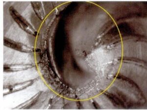
Analys:
In this case, the root of the central spiral in the master mold belongs to a dead corner position, which is difficult to reach with ordinary tools. After sanding, this part still appears rough and cannot be removed.
Solutions:
In the jewelry versioning process, due to the significant structural differences of the master mold, conventional standard tools sometimes cannot handle dead corners, concave areas, etc. A specific tool needs to be made by the workers themself to sand these areas.
[Case 5-26 ] Master mold edges are not smooth, as shown in Figure 5-32.
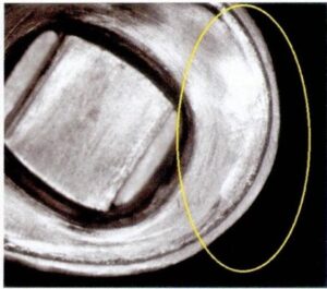
Analys:
When finishing jewelry, edges should be smooth without apparent uneven thickness. The master mold in this example did not meet this requirement, showing noticeable edges that were not smooth, which is related to the operator’s technique.
12. the master mold casting sprue problem
The casting sprue is not only the channel for the metal liquid to enter the mold cavity but also the channel for supplementing the solidifying and shrinking metal liquid for the casting. Whether the casting sprue is set reasonably or not is related to whether the casting is sound, whether the surface is dense, etc., and must be taken seriously. Several common master mold casting sprue setting problems are as follows.
[Case 5-27 ] The casting sprue is too small, as shown in Figure 5-33.
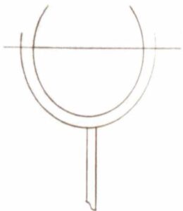
Analys:
When the casting sprue is too small, the rise of the metal liquid level in the cavity is slow, which may lead to defects such as incomplete defects. The scouring force of the metal liquid on the mold wall is large, which can cause defects such as sand holes and blowholes. During the solidification process of the casting, the metal liquid’s supplementary shrinkage channel is blocked, which can lead to macroscopic shrinkage cavities and microscopic shrinkage looseness in the workpiece.
Solutions:
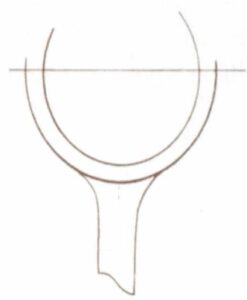
The size of the casting sprue should be determined based on the characteristics of the casting metal material, the size and structural characteristics of the casting, the casting method, etc. Generally speaking, the cross-sectional area of the casting sprue should be 70%-150% at the connection with the workpiece. Therefore, the master mold casting sprue in this example can be appropriately enlarged, as shown in Figure 5-34.
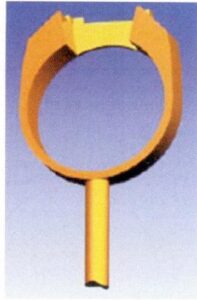
【Case 5-28】The position of the casting sprue does not meet the requirements for filling and shrinking, as shown in Figure 5-35.
Analys:
For the ring, in order to facilitate the subsequent polishing and reduce the impact on the appearance, the casting sprue is generally set at the shank. However, in this case of the ring, the sides of the ring head are solid, thick, walled structures, and these two areas solidify last; their shrinkage cannot be compensated by external metal liquid, resulting in severe shrinkage porosity.
Solutions:
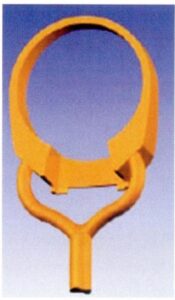
According to the general principle set by the casting sprue, it should be set at the thick wall part of the casting. If the structure of the ring does not allow changes, the ring must be inverted. Double support casting sprues should be set, connected to the thick section respectively; if it is permitted to hollow out the inside of the ring while maintaining the same shape, the thickness of the two thick wall parts can be reduced to be less than the wall thickness of the ring handle. Then, the casting sprue can be set at the ring handle. As shown in Figures 5-36 and 5-37.

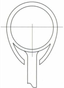
[Case 5-29 ] The position of the casting sprue is challenging to clean, as shown in Figure 5-38.
Analys:
The casting sprue is a process measure required for casting molding, not required by the casting itself. After casting molding, the casting sprue needs to be removed. The casting sprue, in this case, is set in the interlayer of the ring, which is challenging to cut. Tools such as steel files and sandpaper are also complex to enter during modeling, making it difficult to clean the residual casting sprue.
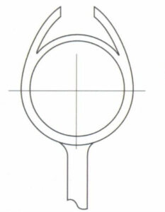
Solutions:
The casting sprue should be set on the outer smooth surface as much as possible for easy cleaning, as shown in Figure 5-39.
【Case 5-30】The casting sprue is connected to the casting at a right angle, as shown in Figure 5-40.

Analys:
When the sprue is connected to the workpiece at a right angle, turbulence is easily generated in the molten metal during the filling process, causing problems such as gas entrapment and slag entrapment, and thermal nodes can form at the connection, leading to shrinkage porosity at that location. If the pressure of the molten metal is high, the gypsum wall facing the flow of the molten metal is easily eroded and abraded, causing defects such as inclusions and sand holes.
Solutions:
The casting sprue should be connected to the casting with a fillet, which can make the filling of the molten metal smooth and reduce abrasion on the mold wall. The size of the fillet should comprehensively consider factors such as the cross-sectional size of the casting sprue, the wall thickness of the casting, and the ease of cleaning.
【Case 5-31】A thin-walled casting has an oversized casting sprue, as shown in Figure 5-41.
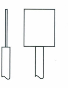
Analys:
Connecting a large sprue to a thin section, if the temperature of the molten metal and gypsum is improper, can cause the sprue to shrink and loosen, extending to the connection area and causing the so-called ‘backflow’ phenomenon.
Solutions:
Setting casting sprues on thin-walled castings to eliminate the misconception that larger casting sprues ensure complete filling. In fact, the filling capacity of the molten metal depends not only on the casting sprues but also on the flow of the molten metal in the mold cavity. The larger and thinner the casting, the easier it is to cool down and cause filling-related defects. At this point, simply increasing the cross-section of the casting sprue will not solve the problem. It is necessary to increase the number of casting sprues and shorten the range covered by each casting sprue in the mold cavity, as shown in Figure 5-42.
