How To Create Lightweight Jewelry Masterpieces With Electroforming
Electroforming Process: From Casting to Surface Treatment
The electroforming process is an electro-deposition molding technology and a new craft technique introduced in the jewelry processing and manufacturing industry. It originated in the United States in the 1960s and was first launched at the Basel Jewelry Exhibition in Switzerland in 1984, including 18K gold electroforming technology and electroformed jewelry. The electroforming process deposits metals or alloys such as gold, silver, and copper onto the surface of a model through electrolysis and then removes the model to form hollow, lightweight jewelry products with a large volume. It compensates for the inability of lost-wax casting to produce thin-walled castings. It solves the defects of mechanical stamping that cannot manufacture large-volume jewelry products with clear details. Compared to lost-wax casting, it has a very thin metal layer, significantly reducing the product’s weight while maintaining the same volume, effectively lowering production costs, and enhancing the competitiveness of jewelry products. This technology can also create special trendy curved series jewelry and various new jewelry styles with seamless surfaces.
Electroforming technology utilizes the combined effects of various chemical components, the speed of equipment operation, temperature, current intensity, and the size of the castings to produce hollow jewelry products. Therefore, in the technical operation process of production work, unlike other manual processes, it is essential to strictly follow the guidance of technical parameters and combine it with practical production experience. A meticulous and scientifically rigorous work attitude is necessary to improve operational levels in production work and achieve a high yield of qualified electroformed jewelry products.
The typical electroforming process mainly consists of interrelated production steps, including sculpting the mold pattern, Copy Mold, injecting wax into the mold, wax mold finishing, applying paste, electroforming, finishing, de-waxing, and polishing.

Schematic Diagram of Electroforming Structure
Sisällysluettelo
Section I The Working Principle of Electrolytic Casting
1. The Working Principle of Electrolytic Casting
2. Basic Structure of Electroforming Technology
The basic structure of electroforming can be divided into four parts, including the power supply, electrolysis tank, circuit, auxiliary mechanisms, and reagents (see Figure 9-1).
(1) Power Supply. Converts a 220 V power supply into a direct current power supply through rectification equipment. The cathode and anode are set up in the electrolysis tank.
(2) Electrolytic tanks. Use corrosion-resistant containers such as glaze tanks and PVC tanks.
(3) Circuit. The workpieces to be electrolytically cast are connected to the cathode, and the anode is connected to the metal plates of the metal ions required in the electrolyte, forming a circuit in the electrolytic cell.
(4) Auxiliary mechanisms and reagents. Filters, mixers, metal salts, acids, bases, and other chemical reagents are needed to prepare the electrolyte.
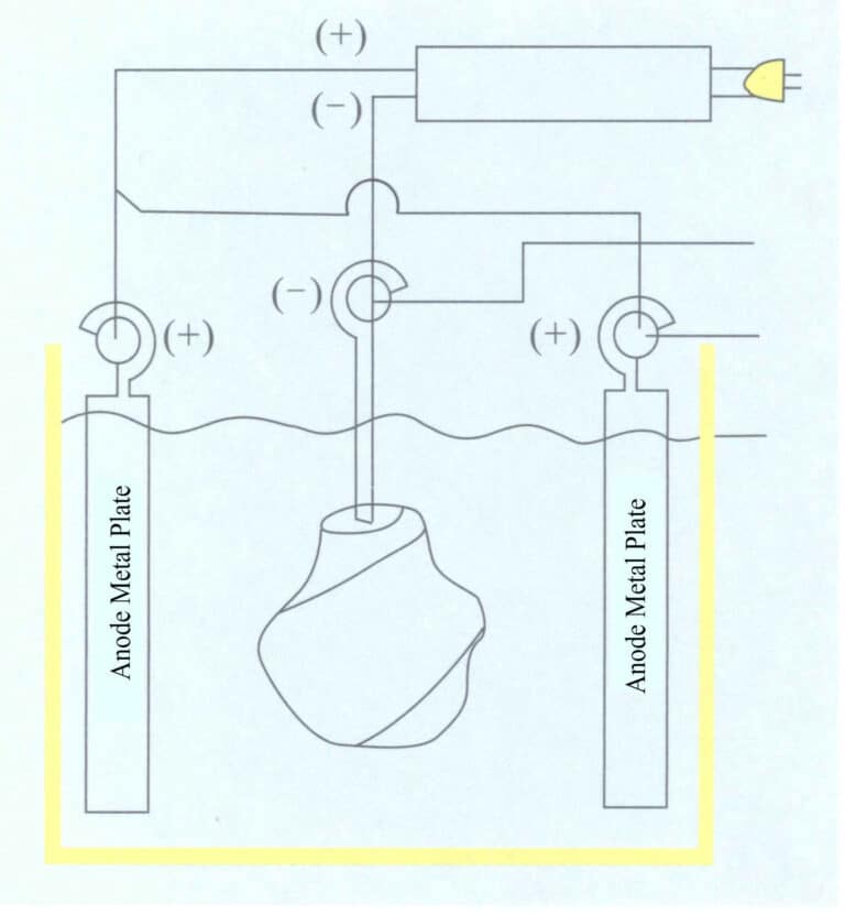
Figure 9-1 Schematic Diagram of Electroforming Structure
Section II Wax Mold Making
1. Sculpting the Pattern
Wax models are usually made from jewelry wax as the raw material, using techniques such as high relief, low relief, openwork, and line carving to create wax patterns.
(1) Main Tools
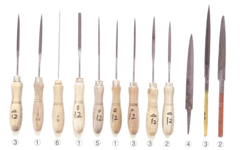
Electric hanging flexible shaft grinder, electric hair dryer, electric soldering iron, desk lamp, various specifications of carving knives, calipers, scribers, files of various shapes and specifications, set squares, tweezers, etc.
(2) Main Materials
Jewelry wax, fine carving hard clay, wood-based soil, gypsum powder, gasoline, sandpaper, etc.
(3) Craft Design
Design is based on the client’s requirements, conceptualizing the ideal pattern. At the same time, it is necessary to consider the primary and secondary aspects of the subject matter and theme, the difficulty of processing procedures and electroforming techniques, the ideal volume and quality of the processed workpiece, and other factors to meet the client’s demands for jewelry and decorative art pieces featuring figures, plants, animals, landscapes, etc.
(4) Initial Rough Carving
The initial rough carving process involves using carving tools to sculpt wax material into a certain shape according to the requirements of the design drawing and process conditions to determine its basic form. This is the initial rough stage of the carving process, and its basic principles are as follows.
① Leave edges when seeing surfaces, using squares instead of circles. “Leave edges when seeing surfaces” is a step in the craft carving process. When carving, one should first view the object to be carved as a geometric body, and by continuously carving the geometric body, divide the large surfaces into smaller surfaces that are close to the minimum shape. For example, when carving a person’s head, one can view the head as a rectangular prism and then divide it into smaller surfaces according to the structure of the head and face.
② Carve the voids and leave the solids. During the carving process, it is common to see some protruding areas of the human body outlined by clothing, which are the solid parts, often the high points. Conversely, some recessed areas are buried within the clothing, the voids. The solid parts should be minimally altered or left untouched, while the voids are the focus of processing, making the solid parts stand out; hence, it is called carving the voids and leaving the solids.
③ Start shallow and then go deep. The main point is to outline the general contours and structure of the three-dimensional image on the plane when depicting the details of the product. One can proceed to greater depth only after checking the accuracy of proportions and shapes.
④ Leave material for carving. Leave some excess material in the appropriate places to allow for further modifications.
⑤ Short neck and high shoulders. This is also a method of leaving material for carving.
(5) Fine Carving, Meticulous Embellishment
Fine carving is done after the initial carving of the blank, addressing various shortcomings from the previous processes and ensuring the surface of the wax mold is smooth and polished. Their main craft techniques include fine sketching, precise positioning and trimming, and fine embellishment.
① Fine sketching. This means drawing more detailed outlines on the initial piece. For example, a person’s eyes, hands, ears, and feet; the petals and leaves of flowers, etc.
② Precise positioning and trimming. After completing the fine sketch, one can deepen the work, refining and detailing the parts of the blank piece and embellishing the decorative lines.
③ Fine embellishment. This mainly involves checking and repairing any deficiencies overlooked in previous processes. After the wax mold is embellished, the surface residues are washed away with gasoline, and a complete wax mold is finished.
(6) Carving Techniques
The carving techniques generally include the following categories.
① Three-dimensional round carving. Currently, most wax molds are made using the technique of three-dimensional round carving, which requires detailed carving on both the front and back sides, while bas relief only needs to be carved on one side.
② High relief. High relief is relatively thick, with a considerable distance between the thickest and thinnest points, some approaching the thickness of round carving. This high relief is often paired with shallow relief as a background to highlight the theme, contrasting the distant and near views.
③ Shallow relief. The distance between its thickest and lowest points is relatively small, with little fluctuation and an unclear three-dimensional effect.
④ Line carving. This technique expresses images through lines, which can be divided into intaglio and relief. Intaglio refers to carving grooves on a flat surface to express the characteristics of the pattern. Relief, on the other hand, uses raised lines to express the characteristics of the pattern, where the process involves preserving the lined areas while lowering the rest with a chisel to highlight the line portions.
⑤ Openwork (hollow carving). This technique involves carving out certain patterns’ “base” or background with a chisel, creating a delicate and translucent effect. Regarding expression methods, there are both point and focal perspectives.
2. Copy Mold, Cutting Mold
The wax mold (also known as a wax pattern ) that has passed the above carving standards is a sample in mass production. The sample must be replicated into a rubber mold to achieve mass production.
(1) Main Equipment and Tools
Vacuum vibration machine, several plastic buckets and basins, rotating discs, flat shovels, brushes, and gloves.
(2) Main Materials
1300 imported silicone, 627 domestic glue, curing agent, and waste sandpaper.
(3) Key Points of the Operation Process
Roll the waste sandpaper into a cylindrical shape according to the size of the template, staple it with a stapler, position the pattern on the fiberboard, and then fix the rolled sandpaper around the outside of the pattern. Pour the silicone and curing agent into the glue basin and mix thoroughly. The ratio of silicone to curing agent is 10: 1 . Mixing time: 627 type glue is 15 〜25 min, 1300 type silicone is 30 〜45 min. A certain distance must be left between the pattern and the sandpaper tube, generally more than 7 mm, but it should not be too thick to avoid increasing the amount of silicone used. Fix the sandpaper tube on a glass surface, vacuum the mixed silicone, inject it into the sandpaper tube (Figure 9-2), and then vacuum again. Generally, it is injected 1/2 first and then glued according to the actual situation after vacuuming by a vacuum machine. After filling the silica gel, put it into the vacuum machine, and put the sandpaper cylinder in the appropriate and stable place for the last vacuuming. Domestic silica gel can be dried naturally in about five hours, while imported silica gel needs 8~12 hours to be dried naturally.
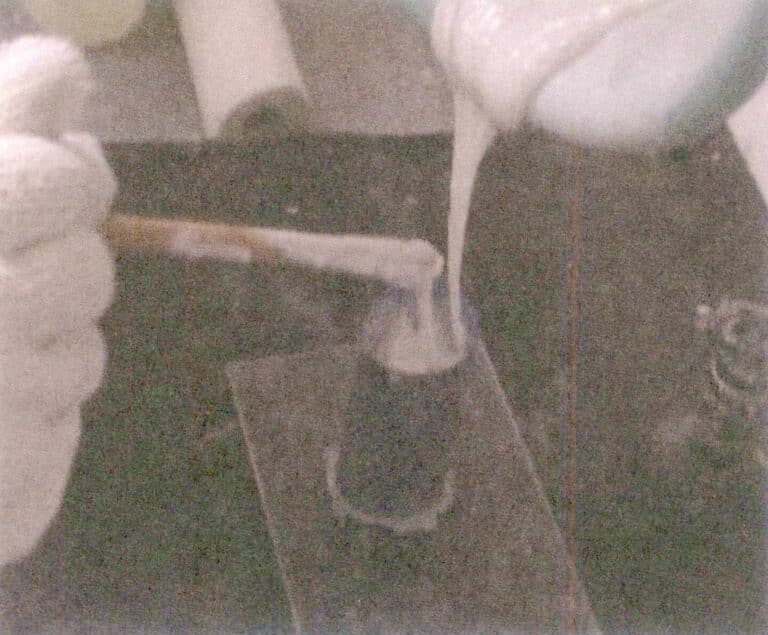
The above is a general method for Copy Mold, while the Copy Mold of large products is somewhat different. The consumption of silicone Copy Mold materials for large products is high, the cost is high, and due to the large volume, it is difficult to vacuum, making quality hard to guarantee. Therefore, it is usually done by applying glue to the pattern and then Copy Mold it with plaster.
Fix the pattern onto the disc, use a brush to apply the prepared silicone onto the template, and carefully check for any missed areas or bubbles. If bubbles are found, they should be dealt with promptly. After the first layer is qualified, repeat the brushing twice, achieving a thickness of 3 〜5 mm (depending on the pattern size). Use oil clay to fill in larger depressions and holes. Then, mix an appropriate amount of water with plaster to prepare the plaster slurry, and use a flat spatula and hands (wearing rubber gloves) to scrape and spread the plaster onto the template, with a thickness of about 20 〜30 mm (depending on the size of the pattern). When scraping and spreading, depending on the complexity of the pattern’s shape, break it down into several parts for production: simple ones into two pieces, complex ones into 3 ~ 4 pieces, or several pieces to facilitate the removal of the silicone mold and pattern as a standard. After making the outer layer of a plaster mold, it is necessary to apply floor wax on the periphery and then make another piece, ensuring they do not stick together for easy disassembly. Once the entire Copy Mold work is completed, it should be allowed to air dry naturally. Use a rubber hammer to knock off the plaster layer for disassembly, then use a scalpel to cut the silicone layer at appropriate positions to remove the pattern. Close the cut silicone mold, use a plaster disassembly mold to hold and fix the silicone mold, and secure it with glue lines and tape; the large Copy Mold work is then completed.
When cutting the mold, choose areas that are easy to repair, making it easier to finish (scrape) the wax mold. Avoid cutting through the facial features when molding for figures or animal statues. After cutting the mold, check the quality of the silicone mold to see if there are any bubbles and whether the silicone molds fit together tightly.
Copy Mold rubber mold video
3. Wax Mold Injection
Injecting wax into the silicone mold creates wax molds for mass production, known as wax mold injection.
(1) Main Equipment and Tools
Electric heating cylinder, oven, vacuum vibrating machine, tweezers, iron spoon, air compressor, rubber mold.
(2) Main Materials
Model 13360 jewelry wax.
(3) Key Points of the Operating Process
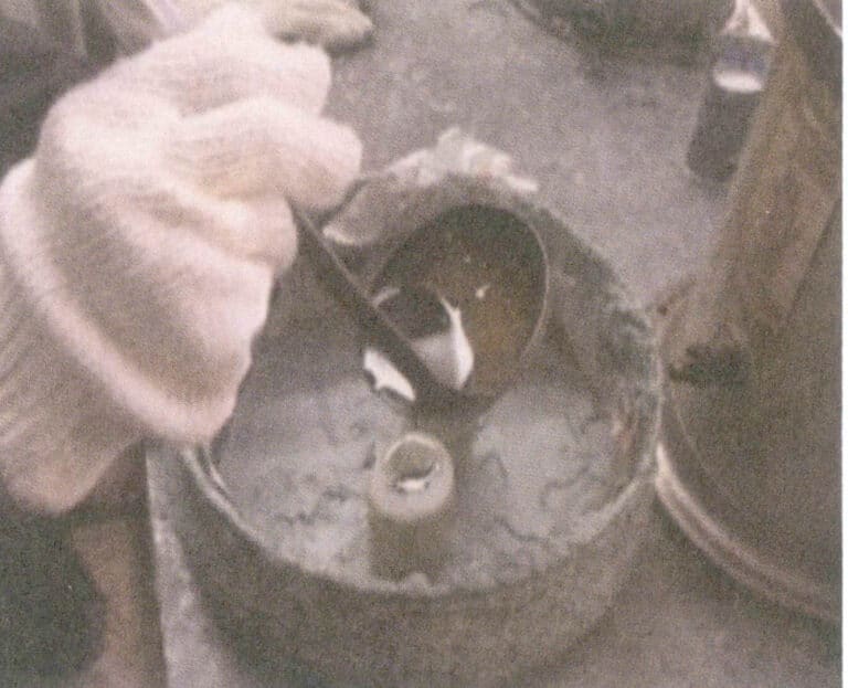
Use compressed air to blow away impurities inside the rubber mold, place the rubber mold in the electric oven to preheat for 5 minutes, allowing the temperature of the rubber mold to reach 60 ~ 65℃, and remove moisture (which can reduce the generation of bubbles during wax injection). Remove the rubber mold from the oven, close it, and ensure the joints are completely sealed, securing it with a rubber band. Use an iron spoon to scoop the wax water from the electric heating cylinder and pour it into the sealed rubber mold (Figure 9-3), then place it in the vacuum vibrating machine to vacuum 1 〜2 min, take out the wax supplement, and vacuum again 1 〜2 min. After completing the wax injection, wax supplement, and vacuum work, place the rubber mold on the workbench to cool naturally. Once the wax injection port solidifies, stand the rubber mold in a plastic basin filled with cold water to accelerate the solidification of the wax. The solidification time depends on the volume of the wax, generally over 30 minutes and sometimes up to 1 day. After the wax mold inside the rubber mold is completely solidified, loosen the rubber band and tape, open the rubber mold, and take out the formed wax mold.
4. Wax Mold modifying
The process of modifying the wax mold formed by wax injection to repair defects, beautify its surface, and meet design requirements is called wax model finishing. The surface of the wax mold after finishing should be smooth, free of impurities, and meet the technical requirements of the electroforming process. If individual wax patterns need to be modified during the wax mold finishing process, they must be reworked back to the wax carving stage.
(1) Main Tools
Carving knife, wax scraping knife, surgical knife, electric soldering iron, desk lamp, tweezers, gasoline, alcohol lamp, brush, etc.
(2) Wax Pattern Finishing
Modify the wax mold to meet the production technical requirements of the electroforming process. Use the wax (original) model to replicate the rubber mold, and when in large quantities, operate according to the process of the wax model→ silver model→ rubber model.
(3) Scraping the Wax (finishing the wax) Mold
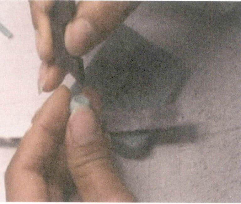
Referencing the original model, use a wax scraper or scalpel to scrape off the flash, wax marks, sprues, etc., from the wax mold, making the entire surface of the wax mold beautiful and smooth (Figure 9-4). Use an electric soldering iron to dot wax to fill small holes and other defects on the wax mold or connect several wax components. Clean the surface of the wax mold with gasoline to make it shiny and smooth (Figure 9-5).
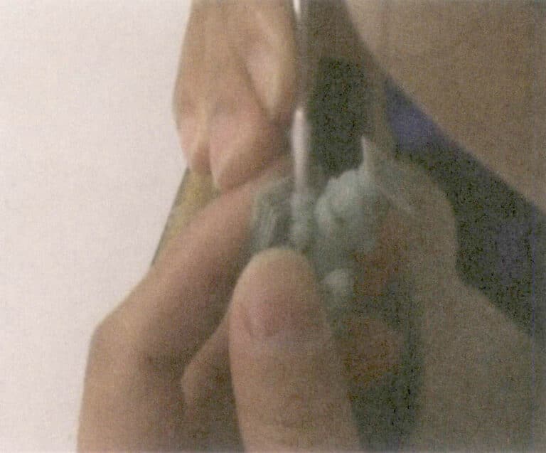
Figure 9-4 Finishing the wax
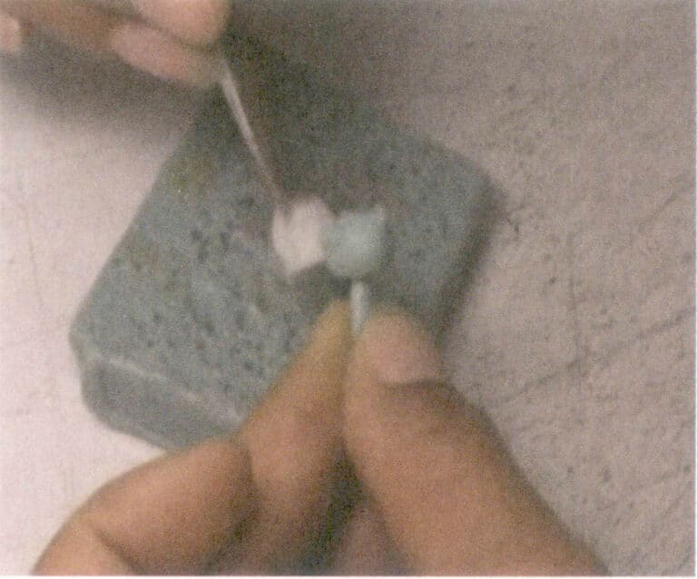
Figure 9-5 Cleaning the wax mold
(4) Engraving Characters
Mark the color, font size, etc., on the wax mold prepared for electroforming. The position of the engraving characters should not affect the aesthetics and must not conflict with the reserved holes and insertion pins for post-processing. Clean the typing stamp mold with gasoline, then stamp it on the wax mold. Do not apply too much force when stamping to prevent the wax mold from deforming; the technique must be correct (Figure 9-6). After stamping, clean the typing stamp mold with gasoline, then stamp on the next wax mold. After stamping, carefully check for burrs at the stamping site; if present, gently scrape with a scalpel or wipe with a gasoline-soaked cotton ball to keep the surface clean and dust-free. Note that gasoline should not remain on the wax mold stamping area for too long; it should dry quickly; otherwise, the stamp will fade, affecting the stamping effect.
Wax mold finishing video
Wax injection and wax finishing video
Section III Hollow Electroforming
1. Inserting the Hanging Rod
To facilitate the electroforming of the casting tank, a hanging rod must be inserted into the wax mold to achieve fixation and conductivity.
(1) Main Tools
Hanging rods of various shapes, electric soldering iron, alcohol lamp, surgical knife.
(2) Key Points of the Operating Process
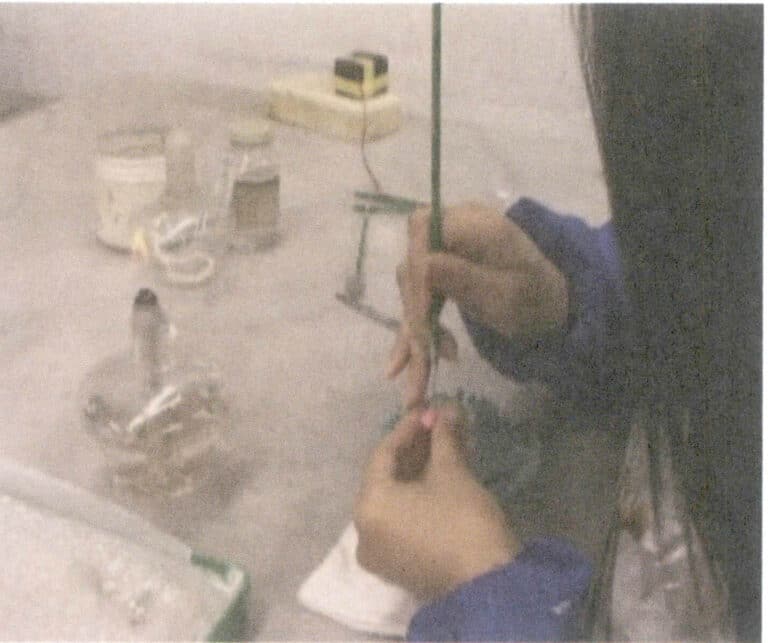
Install the drill bit on the electric hanging flexible shaft grinder, then drill a hole in the appropriate position in the center of the wax mold base, insert the suitable iron hanging rod into the drilled hole, then use the electric soldering iron to dot wax, seal, and tighten the inserted rod with wax, and smooth the sealing wax (Figure 9-7). Alternatively, choose the correct hanging rod, heat it with an alcohol lamp and directly insert into the suitable position in the center of the wax mold base. Then, use an electric soldering iron to dot the wax, seal and tighten the wax at the rod insertion point to prevent the wax mold from falling off during electroforming in the casting cylinder, and then scrape the sealing wax smoothly.
Installing hanging rod video
2. Apply Silver Paste (Conductive Layer)
Since the wax mold is not a conductive material, a uniform layer of silver paste must be applied to the surface of the wax mold. During the silver foil’s natural drying process, the solvent’s acetone evaporates, forming a very thin conductive layer on the surface of the wax mold, thus preparing for electroforming in the casting cylinder.
(1) Main Equipment and Tools
Refrigerator, magnetic stirrer, scalpel, brush, beaker, different drill burs, and a compass.
(2) Main Materials
200#silver paste, 4-methyl-2-pentanone (C6H12O) .
(3) Key Points of the Operation Process
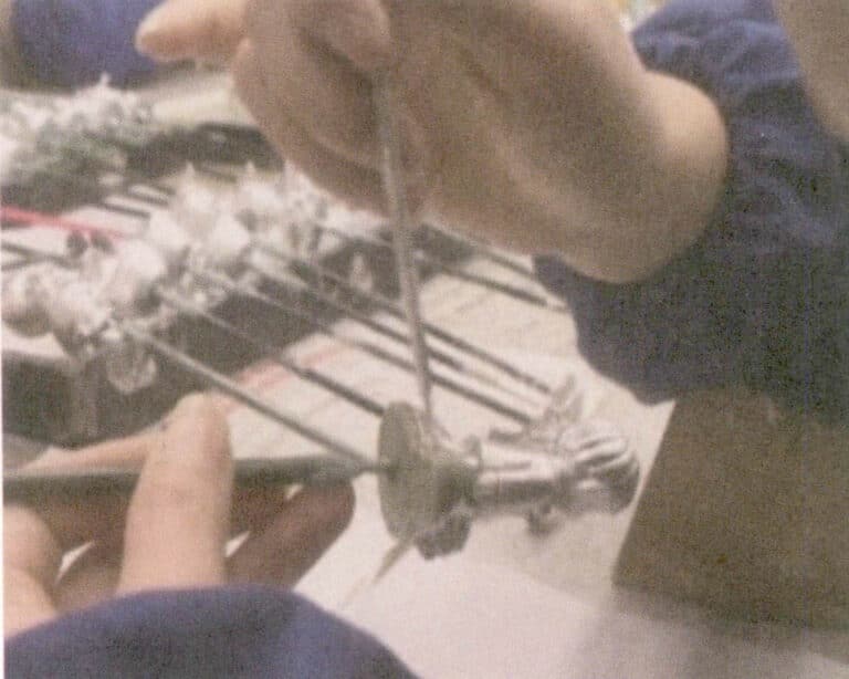
A finer sieve should be used to filter the silver paste to remove the coarser substances in the silver paste. Then, about 300 ml of silver paste should be poured into a beaker containing a magnet and placed in the center of a magnetic stirrer. Once the magnetic stirrer is powered on, the magnet in the beaker will rotate rapidly to stir and keep the silver paste in a uniform state, preventing the surface from becoming scaly. If the silver paste in the beaker becomes too thick, some ketone should be added for dilution. Use a brush to dip into the silver paste and evenly coat the surface of the wax mold (Figure 9-8). The silver oil should cover the joint between the wax mold and the iron hanging rod, and the silver paste on the iron rod should not be too high, ideally around 3 mm. At room temperature, the silver paste will oxidize and accumulate dust. Therefore, the silver paste should be stored in the refrigerator. The silver paste should maintain a certain concentration, ideally with a smooth, white appearance on the surface of the wax sample. The brush should be regularly cleaned with silver paste thinner to avoid adhesion issues.
Coating silver paste video
3. Opening Reserved Holes
4. Preparation before Placing into the Tank
(1) Check and Repair Wax Molds
Check whether any areas on the wax mold have missing silver paste or small silver beads. If there are, they should be repaired promptly; otherwise, it will lead to issues such as holes and beads on the surface of the casting after it is removed from the mold.
(2) Weighing
① Main Tools. Electronic scale, several plastic trays.
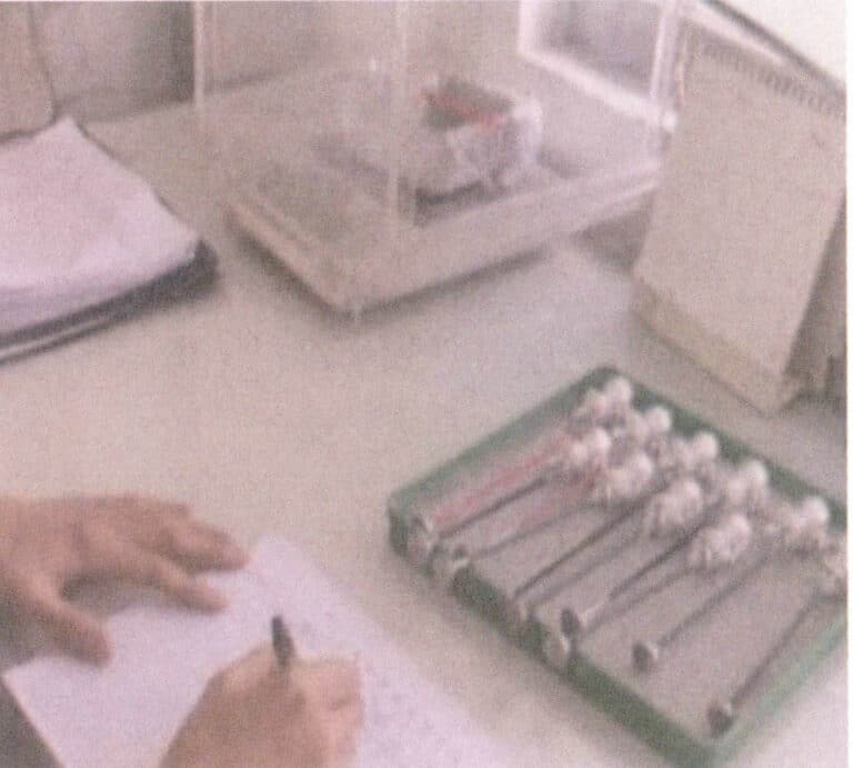
② Key operation points. Adjust the electronic scale to ensure it is stable and suitable. After adding the iron hanging rod to the wax mold, place it on the electronic scale for weighing and record the data in the corresponding “Production Record Form” (Figure 9-9).
Preparation before Placing into the Tank video
(3) Check and Correct the Electroforming Solution and Equipment Indicators
Before the workpiece begins electroforming, it is necessary to carefully check various technical indicators according to technical documents such as “The Role of Additives and Addition Standards,” “Key Points of Electroforming Technology (Parameters),” and “Standards for Gold and Silver Stock in Casting Cylinders.” If any indicators do not meet technical requirements, they should be corrected promptly. Only when all production technical indicators are met can the electroforming of the workpiece proceed? Otherwise, the defect rate or scrap rate will increase.
(4) Methods for Correcting Various Technical Indicators
① Method for supplementing gold salt (potassium cyanide gold). When the gold salt is insufficient in the electroforming solution, the crystallization of the electroforming layer is finer. Still, the cathode efficiency decreases, the allowable upper limit of cathode current density decreases, the electroformed layer is prone to burning, and sometimes the color of the electroformed layer appears lighter. Increasing the gold salt content in the electroforming solution raises the allowable upper limit of current density, improves current efficiency, and is beneficial for the gloss of the electroforming layer. However, when the gold salt content in the electroforming solution is too high, the electroformed layer becomes coarse, and the color is prone to darkening and reddening.
For every 1 g of pure gold electroformed, 1.47 g of potassium cyanide gold (with a gold content of 68.3% ), and 1 mL of gold supplement for electroforming are required. Generally, it is best to maintain the gold content in the electroforming solution at 20 g/L.
Example: In an electroforming tank, 20 pendant ornaments must be electroformed, each casting 11 g of gold. The amount of gold salt to be supplemented in the electroforming tank is =(20 x 11)十 0.683 = 322.1 g (gold salt).
1 L of pure water can dissolve 500 g of gold salt. First, place the gold salt in a beaker, then add 90℃ an appropriate amount of pure water, and stir until completely dissolved. Pour the dissolved gold salt solution evenly into the casting tank. Rinse the beaker with pure water, and pour the rinse water into the electroforming tank.
② Method for adding supplements. The methods for adding supplements include the following two types.
Method 1: This method is suitable when the amount of workpieces in the tank is small.
The amount of additive added is determined by the amount of gold salt supplemented; for every 500 g of gold salt, 341 mL of additive should be added. The additive is added to the electroforming solution in two batches; the required amount of additive is added when supplementing gold salt, and then 1/2 is added during electroforming. Adding the additive in two batches can make the electroforming solution more uniform, the casting speed tends to be average, and it is beneficial for calculating the time to start the tank.
Method 2: This method is suitable when the amount of workpieces in the tank is large.
The amount of additive added is determined based on the weight of the gold cast; that is, for every 1 g of gold cast, 0.7 mL of additive is added. The additive is usually added in two batches, with the 1/2 of the expected amount of additive needed added before the casting falls into the tank. After the casting is removed from the tank, the actual weight of the gold cast minus the weight of the added additive gives the amount of additive to be added again after removal from the tank.
Example: The planned weight of the gold cast for the casting is 100 g. Before the casting is placed into the tank, 50 mL of additive must be added. After removal from the tank, the actual weight of the gold cast is 102 g, so the amount of additive to be added again after removal from the tank should be (102 – 50) = 52( mL).
③ Casting liquid density. In industrial production, the density of a solution is usually expressed in Baume degrees. Baume degree is a method of indicating solution concentration, named after the French chemist Antoine Baume. Typically, a Baume hydrometer is immersed in the measured solution, and the reading obtained is the Baume degree. The following equation can express the relationship between Baume degree and density: Baume degree =C-C÷D. Where C is a constant 144.3, D is the density.
For example, the Baume degree of pure water is 0°Be’. If the density of the electroforming solution in the electroforming tank is greater than that of water by 10%, then the Baume degree of the electroforming solution is 13°Be’.
Measuring casting liquid density: Clean the hydrometer with pure water, place it into the electroforming solution, wait for stabilization, then read the data on the hydrometer and record it. The hydrometer must be cleaned with pure water after each use. During normal production, the density of the electroforming solution should be maintained at 10 〜20 Baume degrees, with 10 Baume degrees being optimal when opening the tank. Different companies have different formulations for electroforming solutions, and the requirements for Baume degrees may vary slightly. Wire sand workpieces have higher requirements for the density of the electroforming solution; if the Baume degree is too high, it will affect the wire fuzz effect, and at this time, pure water should be used to dilute and adjust the Baume degree of the electroforming solution.
④ Temperature. Temperature is one of the important factors affecting the range of current density and the product’s appearance.
Increasing the temperature can enlarge the allowable range of cathodic current density. Still, if the temperature is too high, it can make the electroforming layer rough, especially the top, easily turn red, and in severe cases, it can become dark, black, deformed, or cracked. When the temperature is low, the range of cathodic current density shrinks, and the electroforming layer can become brittle and bubbling when burned. Therefore, during the production process, the impact of temperature on the electroforming layer cannot be ignored. Due to different suppliers having different formulations for electroforming solutions, the requirements for temperature may also vary.
⑤ pH value. The pH value in the electroforming solution is a commonly used quality control indicator. Accurately measuring and adjusting the pH value of the solution is key to ensuring the quality of electroformed parts. When the pH value is too high, defects such as sand holes and rough spots may occur; when the pH value is too low, it can lead to areas on the casting lacking gold powder, resulting in a dark red color. Whether the pH value is too high or too low, the hardness of the electroforming layer will decrease.
The methods for measuring the pH value of the electroforming solution mainly include the pH paper method and the measuring instrument method. When using pH paper to measure the pH value of the electroforming solution, immerse one end of the paper into the solution to be tested for 5 seconds, then remove the paper and compare it with a standard color chart to determine the pH value range of the solution. This method is simple and suitable for on-site monitoring, but its accuracy is relatively poor.
A measuring instrument is usually used to accurately detect the electroforming solution’s pH value. The specific operation method is to turn on the power, press the test switch, and check whether the measuring instrument is functioning normally.
Place the measuring instrument’s test tube into the casting tank (2.5 cm below the solution surface), approximately 3 〜5 min, to measure the pH value and record the number. After testing, turn off the power and clean the test tube.
If the pH value is high, an appropriate amount of acid adjustment solution can be added to the electroforming solution.
When the pH value is low, a potassium hydroxide solution with a concentration of 10% can be used for adjustment.
⑥ Determination of current density. Current density is one of the operational variables during electroforming, and every electroforming solution has a range of current density that can produce a good electroforming layer. Generally, when the cathode current density is too low, the cathode polarization effect is small, and the crystallization grains of the electroformed layer are relatively coarse. Therefore, very low cathode current densities are rarely used in production. As the cathode current density increases, the polarization effect of the cathode also increases, and the crystallization of the electroformed layer becomes finer and denser. However, the current density on the cathode cannot be too high and must not exceed the allowable upper limit. If it exceeds the allowable upper limit due to the severe lack of metal ions near the cathode, a metal coating shaped like branches may appear at the tips and protrusions of the cathode, or a loose casting layer shaped like a sponge may form on the entire cathode surface. Therefore, the size of the current density has a significant impact on the quality of electroformed products.
The formula for determining current density: Current density = Current÷Surface area of the wax mold (Unit: A/dm2 )
Measurement of the surface area of the wax mold: Stick adhesive paper all over the wax sample formed by injection molding, ensuring the adhesive paper does not overlap. Remove the adhesive paper and stick it on graph paper to calculate the area. Sum and record the surface area of the wax mold used for being placed into electroforming tank. Classify and register the area measured each time according to the wax mold number in a summary table for reference during repeated production.
⑦ Adjustment of current density. In the electroforming production process, the current density is mainly adjusted by adjusting the current size.
For example, The area of the wax mold in the casting tank is 10.56dm2, and the desired current density is 0.45 A/dm2, so the adjusted current is 4.747 A. Calculation formula: 10.56 x 0.45 = 4.747 (A).
The general rules for the influence of current density on electroformed parts are as follows: The current density for general water-sand workpieces is 0.4 〜0.8 A/dm2; the current density for general line-sand workpieces is 0.25 〜0.6 A/dm2; the current density for general silver workpieces is 0.5 〜1.0 A/dm2.
If the current density is too low, the surface of the sanded and flocked product will not show clear lines, and the coating will be relatively smooth; the surface of the water-sand product will not be smooth enough, resulting in the appearance of beads, and the electroformed layer will have a dull color and lackluster. The electroformed layer will be soft, dark, and rough if the current density is too high. In severe cases, it may be slightly brittle, with the possibility of other metal impurities depositing, leading to a common brown or black appearance on the surface of the casting. During production, it is essential to closely monitor the current situation, check various process parameters, and take timely measures to adjust if the current density exceeds the required range.
⑧ Clean the electroforming solution. Various impurities mixed in will affect the structure, appearance, weldability, and conductivity of the electroforming solution. When metal impurities are mixed in, they are very difficult to remove. In the electroforming solution, if there are small amounts of sodium ions, it can easily cause anode passivation, and over time, the electroforming solution can also turn brown. Therefore, during production, it is important to manage carefully and ensure the cleanliness of the electroforming solution. To clean the electroforming solution, first, use a filtration pump to maintain regular filtration, keep the casting solution pure, and replace the filter element regularly; second, prevent dust and impurities from the work area from falling into the casting tank, as even small impurities and dust can pose quality risks; third, pay attention to the maintenance of the pure water machine, and strictly prohibit the addition and use of substandard pure water; fourth, filter the electroforming solution with activated carbon once every six months or regularly.
Electroforming Pre-treatment Video
Copywrite @ Sobling.Jewelry - Custom korujen valmistaja, OEM ja ODM korut tehdas
5. Electroforming after Placing in the Tank
(1) Placing the Wax Mold in the Tank
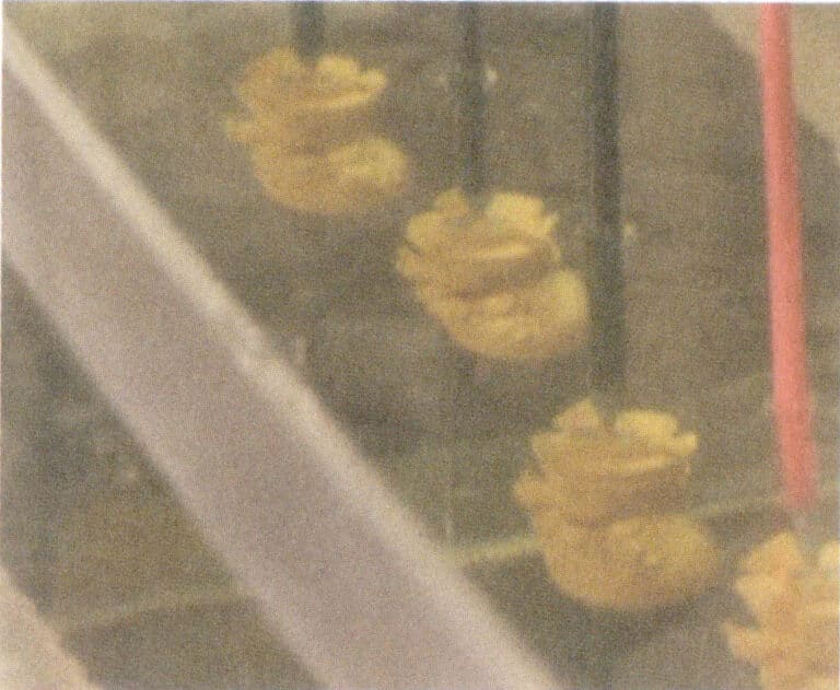
Before the wax mold is placed into the tank, the surface must be cleaned with pure water to remove dust; otherwise, the casting may develop perforations due to dust. Areas with many recesses in the wax mold should face the metal mesh inside the casting cylinder to ensure a uniform casting speed in the recesses and maintain the uniformity of the electroformed layer. Otherwise, the casting speed in the recesses will be slow, resulting in a thin casting layer after removing the tank, which may lead to perforations after grinding and wax removal.
(2) Observation and Handling
When starting the electroforming operation, it is important to enhance observation and stirring to prevent bubbles from adhering to the surface of the wax mold, which could affect the integrity of the electroforming layer and avoid perforation. During processing, remove the wax mold and hanging rod from the cathode plate and move them into the electroforming solution to eliminate bubbles on the wax mold.
(3) Handling of Midway Mold Lifting and Placing Situations
During the electroforming process, if there are special situations, such as power outages or adding silver paste, the workpiece must be removed from the tank and soaked in pure water. If the stay time is too long before returning to the tank, it must be cleaned and degreased to prevent the electroforming layer from forming interlayers, which may bubble when exposed to high temperatures.
(4) Weighing and Calculating the Casting Speed
To control the upper casting speed and the weight of the casting, it is necessary to weigh the casting during the electroforming process. The number of weighings depends on the specific situation, generally 1〜2 times. Weighing can be done once around 4〜7h after the mold is dropped, and the electroforming time for castings usually takes several hours.
Weighing: Remove the casting from the casting cylinder, wash it with pure water, and then weigh it on a calibrated electronic scale, recording the number in the corresponding “Production Record Form.” During weighing, if any flocked and sanded products show missing silver oil or the presence of gold beads, use a scalpel to scrape off the gold beads and promptly reapply silver paste to the areas with missing silver paste before returning it to the electroforming tank.
Calculate the casting speed and estimate the cylinder start time:
Expected quality= casting-in quality + required quality
Casting quality= weighing quality – casting-in quality
Casting speed= casting weight/electro-casting time (Unit: g/h )
Required casting time (mold lifting time)= (expected quality – already casting quality)/ casting speed
Example: The casting quality of a product is 36.6 g, and the required electroplated gold weight (net gold weight) is 30 g. After 6 hours in the tank, it is taken out and weighed, resulting in a weight of 45.4 g.
Solution: Expected quality: 36.6 + 30 = 66.6 g
Casting quality: 45.4 – 36.6 = 8.8 g
Casting speed: 8.8 ÷ 6 ≈ 1.47 g/h
Time required for re-casting: (30 – 8.8)÷1.47 ≈ 14.4 h
At the expected lifting time, take out the casting for weighing. If the quality meets the required range, you can lifting the mold. After cleaning and drying, weigh again, remove the hanging rod from the casting, register it, and hand it over to the next process.
Electroforming after placing in the tank
Section IV Surface Treatment
1. Finishing
Preliminary treatment of the casting surface to remove burrs (commonly used for water-sand workpieces).
(1) Main Tools
Electric hanging flexible shaft grinder, a set of torches, flat files, half-round files, sandpaper, needle-nose pliers, flat-nose pliers, etc.
(2) Key Points of the Operating Process
Perform sand polishing, sandpaper finishing, and repairing the surface of castings (water-sand workpieces) (Figures 9-11).
Finishing video
2. Wax Removal, Silver Paste Removal
Remove the wax and silver paste (conductive layer) from inside the casting, making the casting a complete metal body and a hollow, multi-layered jewelry craft casting.
(1) Main Equipment, Tools
Ultrasonic cleaner (overflow type), wax removal machine, electric burnout oven, Hanlin protection, blowtorch, tweezers, mesh sieve (plastic), air pressure gun, iron tray, stainless steel sieve, etc.
(2) Main Materials
De-waxing solution, nitric acid.
(3) Key Points of the Operation Process
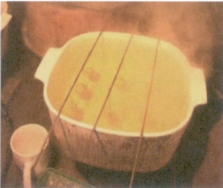
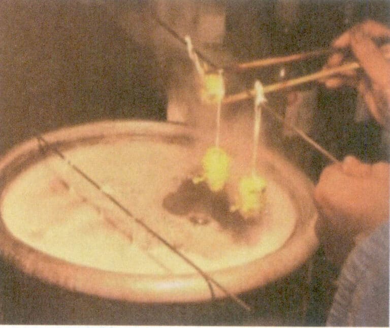
① Wax removal. First, place the workpiece in a stainless steel sieve tray inside a resistance furnace at 100 〜150℃, with an iron tray underneath to catch the wax. Bake at 20 ~ 30 min to extract the wax from the workpiece (the wax can be filtered and reused). Remove the workpiece while hot, gently shake it to pour out any unbaked wax, wrap it in a plastic bag leaving a vent hole, and place it in a plastic sieve. Use an ultrasonic wax removal machine to eliminate residual wax, and after the wax is removed, remove the workpiece and pour out the water inside. Place the wax removal solution into the wax removal machine (the ratio of wax removal solution to water is 1:20 ), and adjust the temperature so that the wax removal solution is above the melting point (80 〜100℃) or boiling point of the wax. Place the casting into the wax removal machine (for small quantities, a rice cooker can be used) for wax removal, with a working time of about 5 ~ 10 min. Protect the flocked and sanded workpiece with cotton cloth and hang it in the wax removal machine using cotton cloth straps, and use chopsticks (wrapped in cotton cloth) to lift the casting for wax pouring, allowing the wax solution to flow out from the bottom hole of the casting. Repeat until the water flowing from the casting is clear (see Figures 9-12). Place the casting in an ultrasonic cleaner to clean it and remove any residual dirt; the cleaning time is 3 〜5 min. Rinse the surface of the casting with tap water, use an air compressor to blow dry the water droplets inside and outside the casting, and leave it on the workbench to air dry naturally.
Suppose the thickness requirement for the electroformed part is very thin to avoid deformation during grinding. In that case, the electroformed flocked and sanded workpiece should be ground first and then wax removed, while the water sand workpiece can be wax removed first and then ground. After wax removal, the flocked and sanded workpiece should be burned with a torch, while the water sand workpiece should be placed in a resistance furnace. Special care must be taken when handling the flocked and sanded workpiece. It must not collide with any objects; even a slight collision will create defects that cannot be repaired. When placing the flocked and sanded workpiece, use a cloth to cushion them, placing each in its position without overlapping.
After de-waxing, please place electroformed silver workpieces in a resistance furnace at 300 ~ 400℃ for 30 minutes. The purpose is to burn off the wax, oil, and de-waxing water remaining on the silver workpieces and to eliminate internal stress. If the color is darker, it should be boiled in alum water or burned with a torch (the flame should not be too strong, and the silver workpiece should not be heated red, as this may cause the silver layer to crack). The purpose is to burn off the wax, oil, and de-waxing water remaining on the silver workpieces, and to whiten their color, forming a passivation film that enhances the silver surface’s oxidation resistance.
② Remove silver paste. Remove the silver paste (conductive layer) applied before electroforming (metal workpiece).
Key points of the operation process: Pour concentrated nitric acid with a concentration of 65% 〜68% into the Hanlin pot, and place it on the electric furnace to heat. When the nitric acid reaches its boiling point, place the prepared casting into the nitric acid to boil. The working time depends on the casting size and the silver paste’s thickness, generally boiling for 45~60 min until no yellow smoke is emitted, at which point the silver paste inside the workpiece can be removed (see Figure 9-13). During the boiling process, gently stir the workpiece a few times with a glass rod to promote the chemical reaction between the silver paste and nitric acid (as nitric acid reacts with silver paste to produce soluble silver nitrate). Occasionally, the nitric acid from inside the casting is poured out, and the silver paste inside the casting will be removed along with the nitric acid. After removing the silver paste, the casting should be washed several times with clean water, cleaned thoroughly with an ultrasonic cleaning machine, and blown dry with an air gun to remove water droplets inside and outside the casting.
Nitric acid is highly corrosive, so care must be taken during operation, and specialized protective gloves must be worn. Nitric acid is volatile; after using it 3 ~ 5 times, replenish or replace it based on the amount and purity of the nitric acid.
Wax and silver paste removal video
3. Happokastelu
Through the acid dipping process, dirt and spots from the surface of the casting are removed.
Place hydrochloric acid with a concentration of 36% ~ 38% into the Hanlin box, and use a blowtorch to heat the casting until it turns red, with the areas with small holes facing up. When etching, first immerse a part of the casting in the acid, and after hearing a sound, immerse the entire piece for about 3 seconds before removing it and rinsing with water.
4. Burnout
5. Sandblasting
A sand surface effect is produced in specific areas of the electroformed parts.
(1) Main Equipment
Water sandblasting machine, dry sandblasting machine, and air gun.
(2) Main Materials
Quartz sand (2# coarse sand, dry sand, glass sand, etc.).
(3) Key Points of the Operation Process
Seal the non-sandblasted areas with tape, and spray coarse or fine sand as required. Sandblasting is divided into dry sandblasting and wet sandblasting. The surface processed by dry sandblasting is coarser, while the surface processed by wet sandblasting is finer. Wet sandblasting involves adding an appropriate amount of water to the sand material to create a sand-water mixture, reducing the impact force of the sand material on the workpiece surface, thus making the sand lines on the workpiece surface more uniform.
Before sandblasting the workpiece, unscrew the spiral cap of the sand powder tank of the sandblasting machine and add quartz sand as required, ensuring the sand amount does not exceed the scale line. After adding sand, tighten the cap and connect the power supply. Adjust the pressure gauge of the sandblasting machine to be between 400 〜600kPa. Adjust the water pressure to be between 100〜 and 500kPa. Wear rubber gloves, hold the workpiece in one hand and the sandblasting gun in the other, step on the power switch, and aim the sandblasting nozzle at the workpiece to spray evenly (Figure 9-14). Visually check the distance and observe the sand effect, spraying until the requirements are met.
Clean the sandblasted workpiece with hot water, use an air gun (compressed air) to blow off the water droplets on the workpiece, and then use a hairdryer to dry it.
The air and water pressure during sandblasting should be controlled within the specified range. If the air pressure is too high, it can easily enlarge the sand holes, and the sand surface may wrinkle; if the air pressure is too low, the sand surface will be thinner and have poor gloss, affecting the sandblasting effect.
Hiekkapuhallusvideo
6. Polishing
Polishing certain areas of the castings can make the product appear more eye-catching and dazzling.
(1) Main Equipment and Tools
Vacuum electric furnace, electric hair dryer, blowtorch, steel press, agate press, file, tweezers.
(2) Main Materials
Gleditsia sinensis
(3) Key Points of the Operation Process
Before polishing, dip in acid, rinse with clean water and check the surface of the casting for any stains. If there are stains, scrub with a toothbrush dipped in wood eye water (if not cleaned properly, use a steam cleaner). A steel press is used to brighten the surface of the casting, and an agate burnishing knife is used to repeat the areas pressed by the steel to enhance the luster and vitality of the casting (Figure 9-15). After the polishing work is completed, clean the surface of the workpiece with clean water, then place it flat in an aluminum tray lined with a soft cloth without overlapping, and use a hairdryer to dry it.
Polishing video
7. Immersion of Protective Agent
The main purpose is to enhance the surface protection of the workpiece and prevent the silver workpiece from discoloring.
(1) Main Equipment
Hook-arm electroplating tank.
(2) Main Materials
AQ-10 concentrate.
(3) Key Points of the Operation Process
Shake the AQ-10 concentrate before use. To prepare 100 L of solution, mix 5〜10L concentrate (8 L is the optimal), working temperature 35 〜45℃ ( 40℃ is the best), immersion time 1 ~ 5 min (3 min is the best). The amount of solution prepared depends on production needs.
Place the workpiece to be immersed in the protective agent on the hanging rack, put it into the chemical degreasing and electro-degreasing tank to clean the surface oil for 1 〜2 min time; clean in a pure water tank; then place it in a heated, clean water tank at around 60℃ for cleaning, slightly heated; immerse in the protective agent tank 2 〜3 min (Figure 9-16). Take the workpiece out of the protective agent tank and immerse it in pure water 3〜5 times. After cleaning, use an air compressor to blow dry the water droplets inside and outside the workpiece, then use a hair dryer to dry it, and finally, place it in the electric oven to dry.
Immersion of protective agent video
Surface Treatment Video


