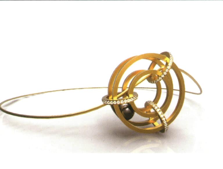
Final rendering

Rhino
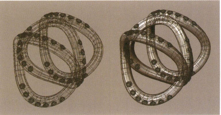
NURBS surfaces of Rhino
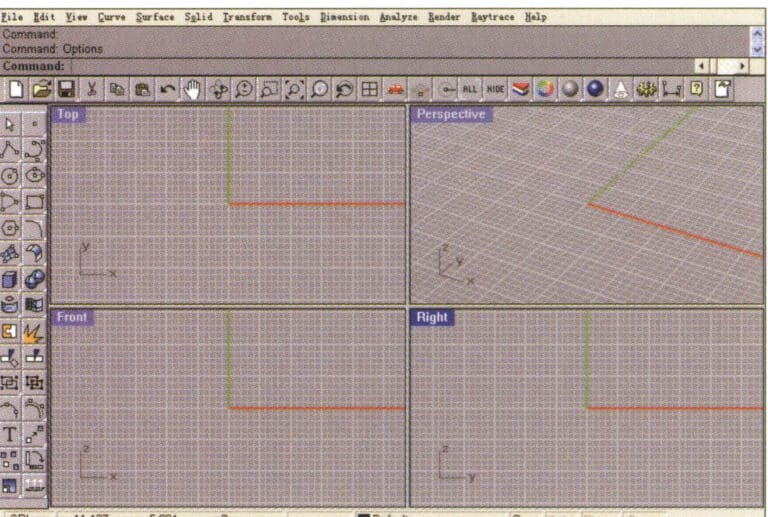
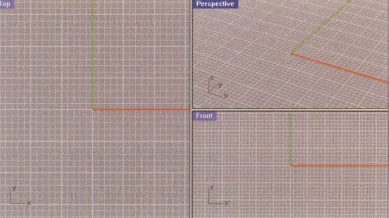
Rhino's operating interface
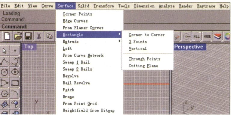
Rhino Menu

Prompt box
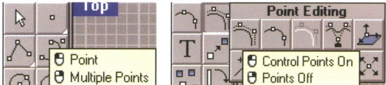
Pop-up tool button and pop-up toolbar
Switch the small view to the large view
Command line
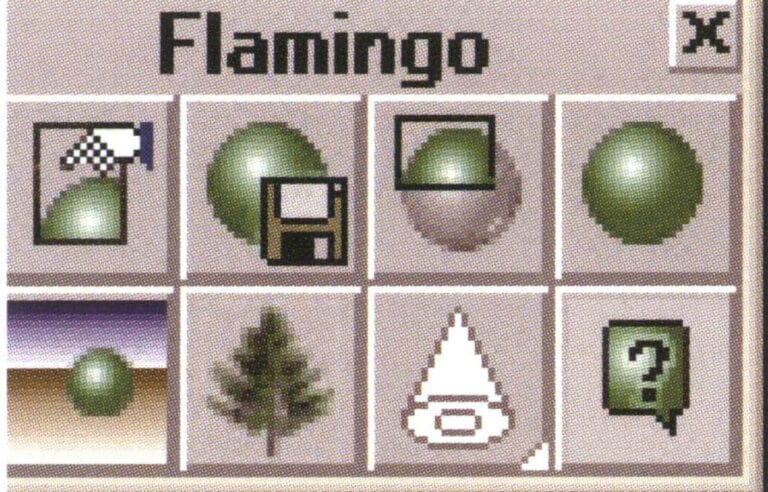
Flamingo command icon
Renderer Flamingo

State bar
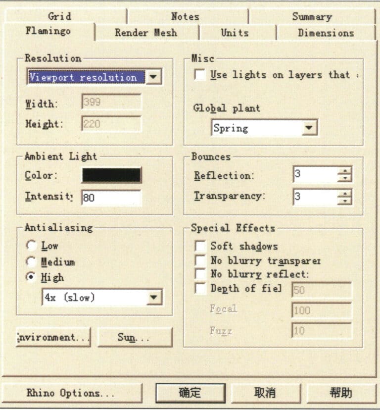
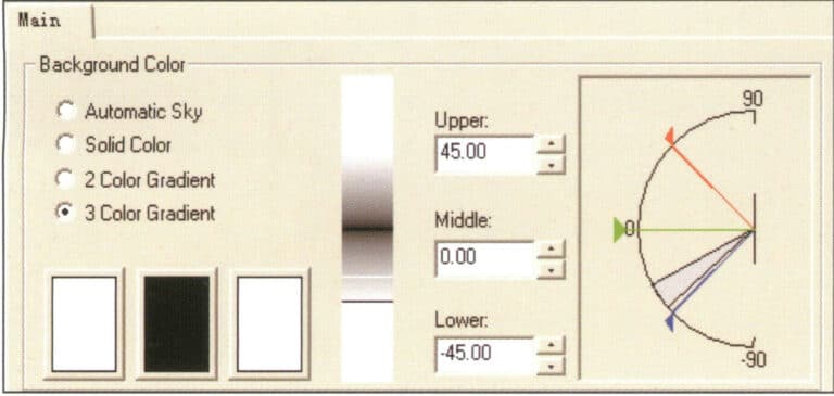
Flamingo rendering settings
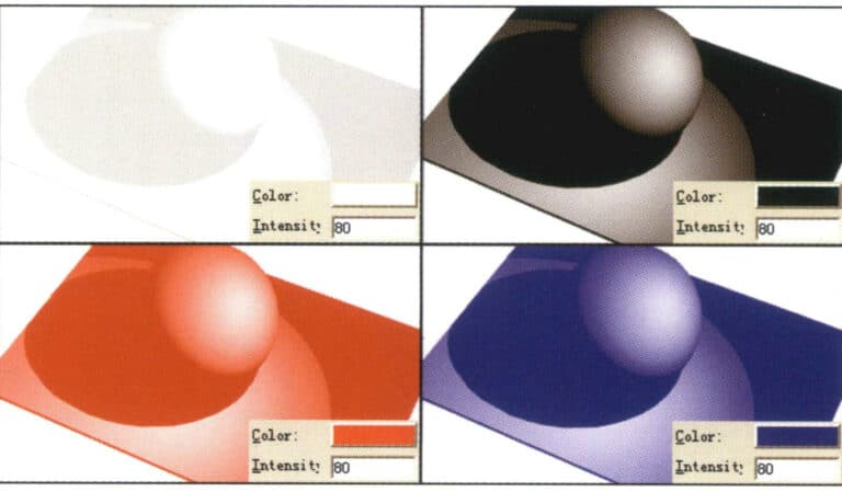
Color - The color of light
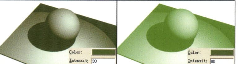
Intensity——The density of light
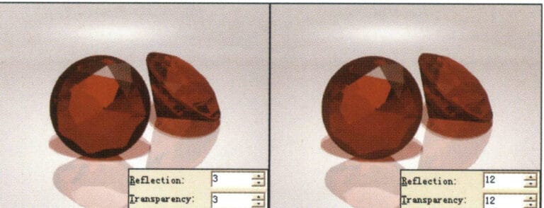
Bounces options
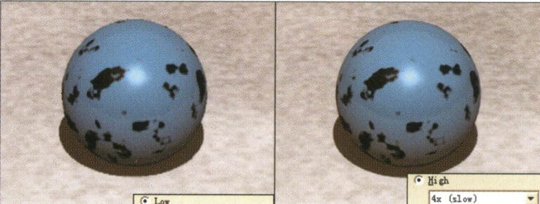
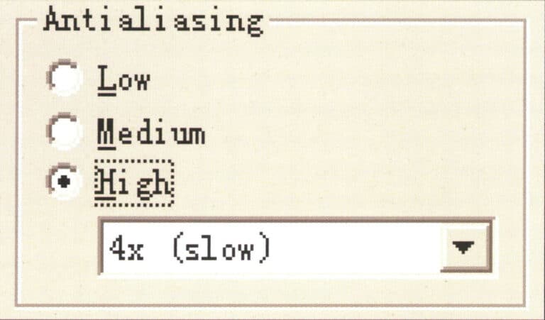
Antialiasing options

Special Effects (Special Tools) options
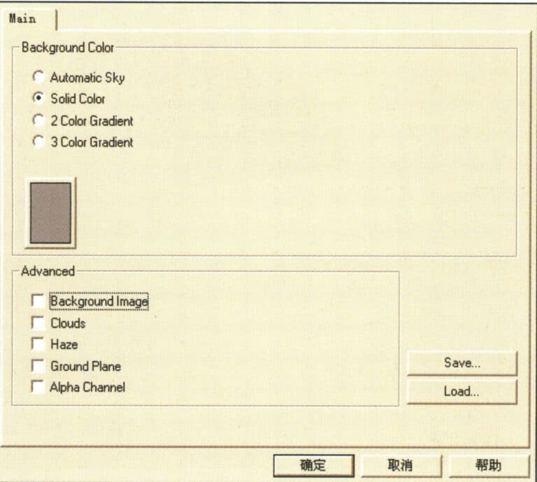
Environment options
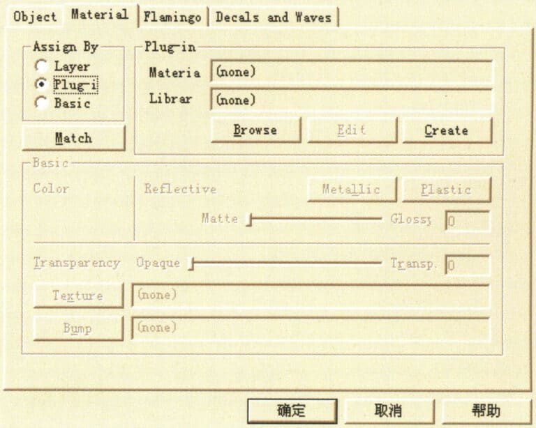
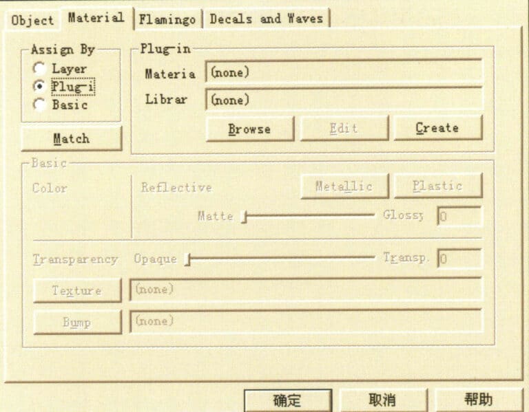
Object Properties dialog box
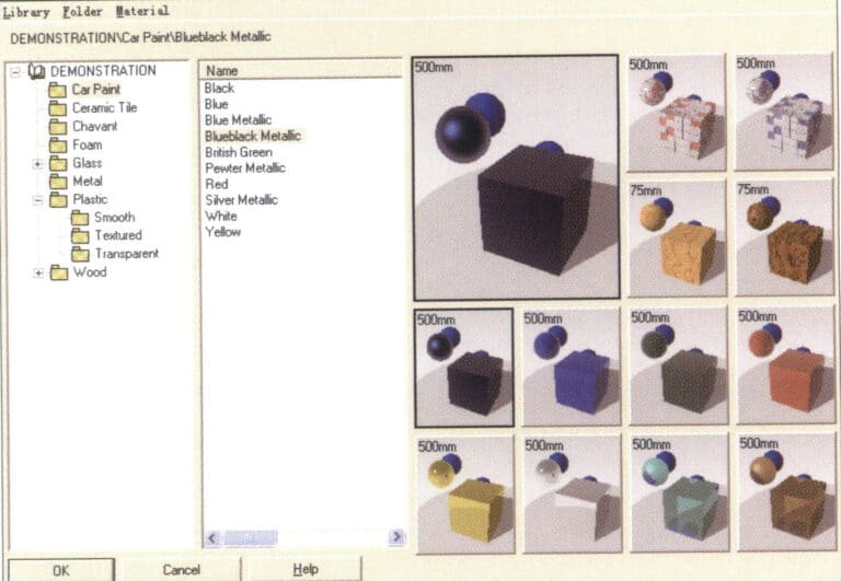
Material Library Dialog Box
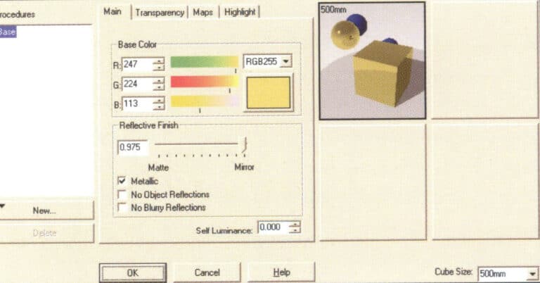
Material Editor Dialog Box

TechGems main module icon

TechGems
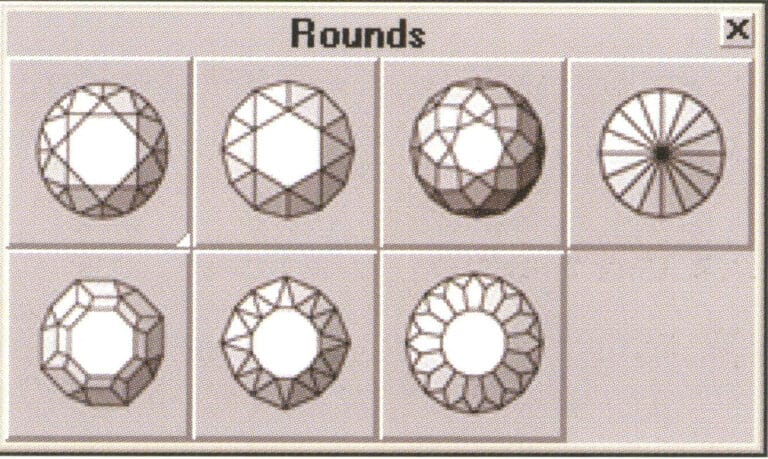
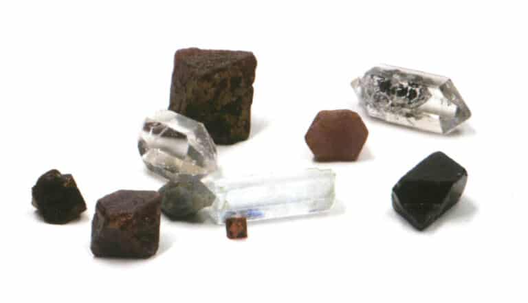
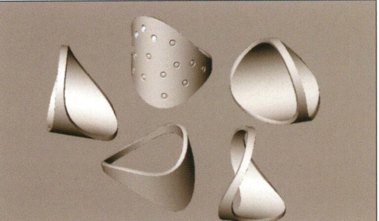
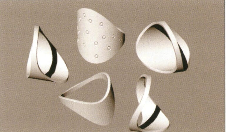
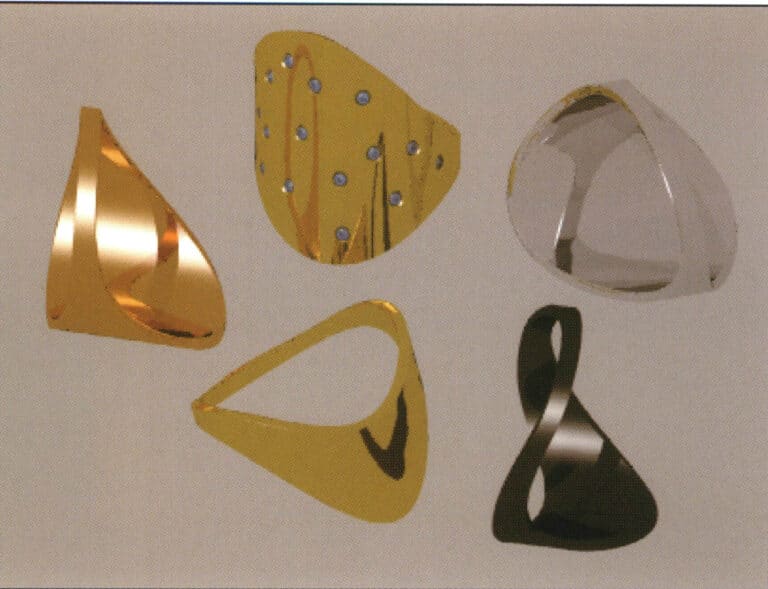
TechGems various round gemstone models
Round diamond model icon
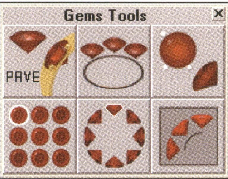
TechGems comes with six tool editing commands.
Gem Tool Icons
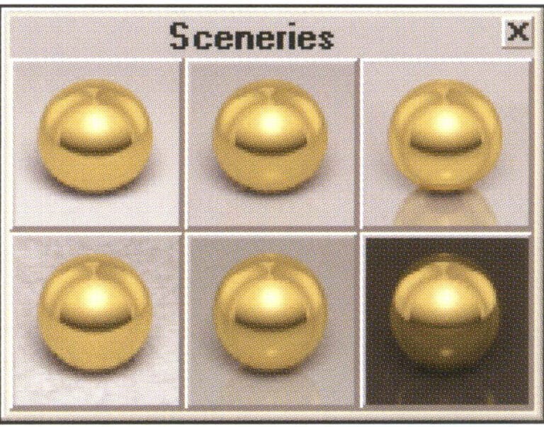
TechGems 1.1 provides six scene options.
Adjustable scene file icon

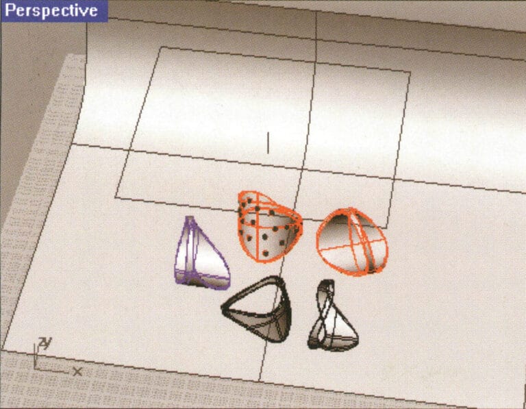
Object view
Enter Material Library
Rhino test rendering
Flamingo test rendering
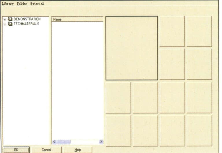
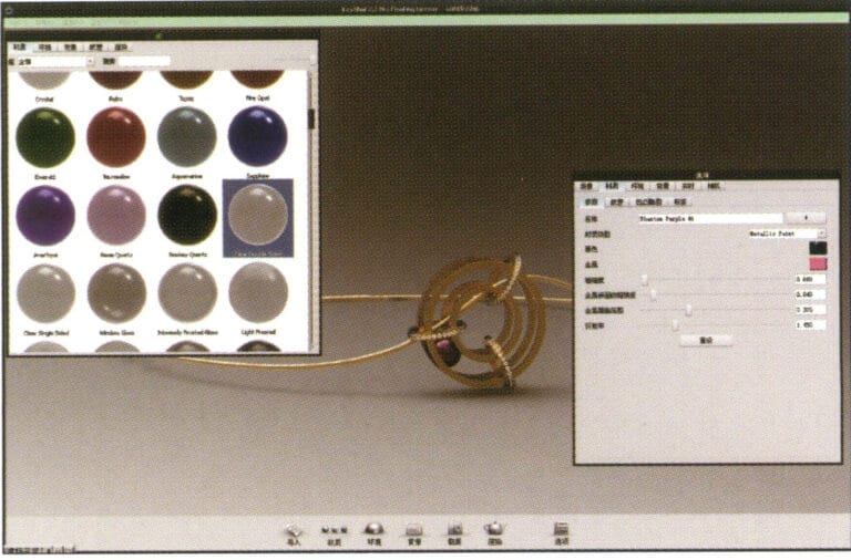
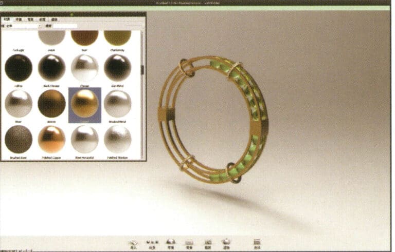
Material Library
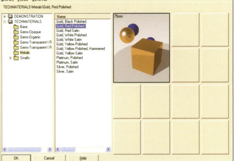
Choose the appropriate material
Gemstone material style
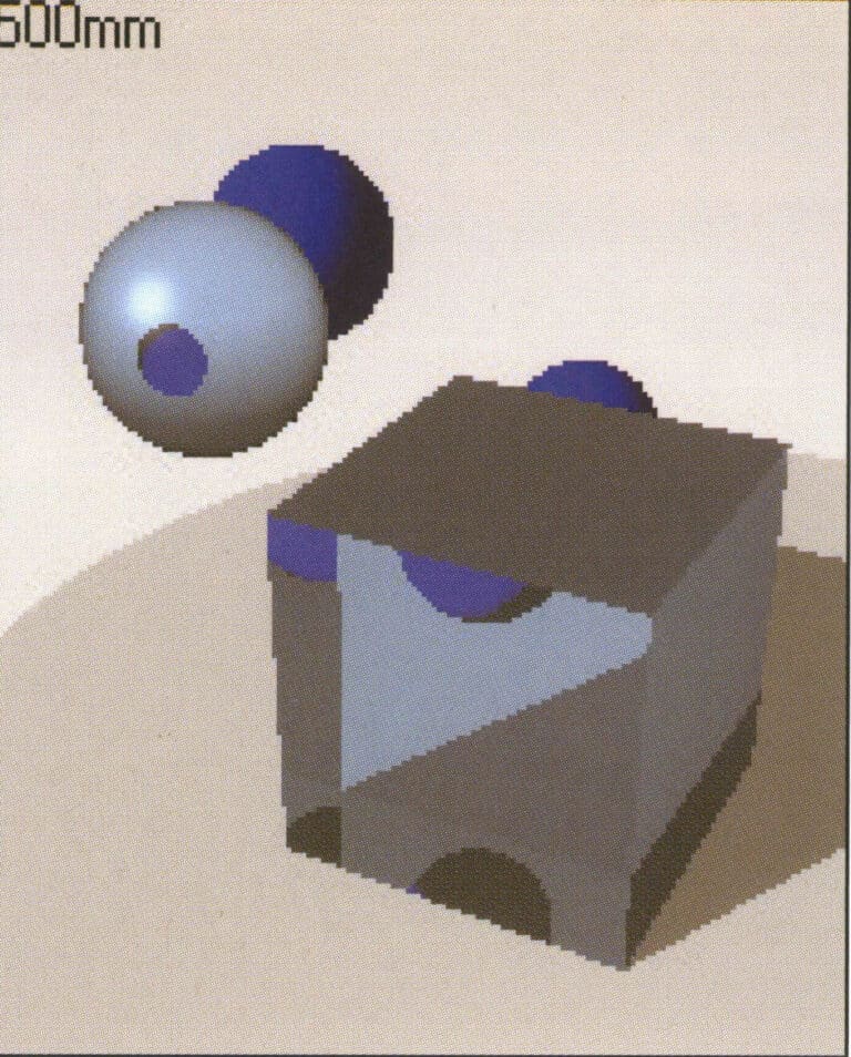
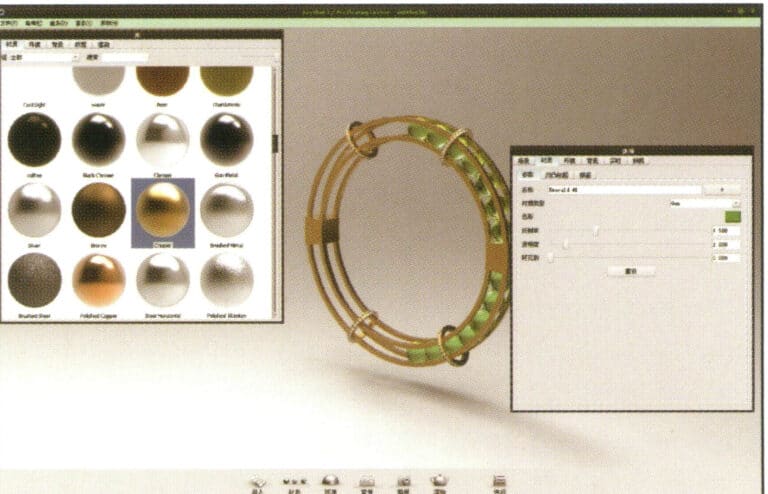
Test rendering
Test rendering

Test rendering
Environmental color change settings
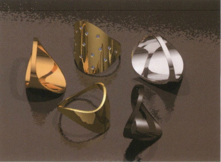
Test rendering
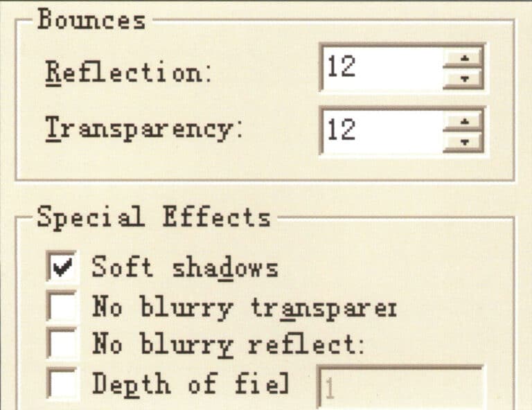
Setting Reflection and Bounce Values
Test rendering
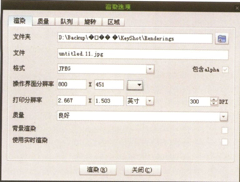
Set the antialiasing capability of the image
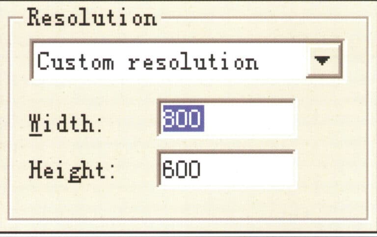
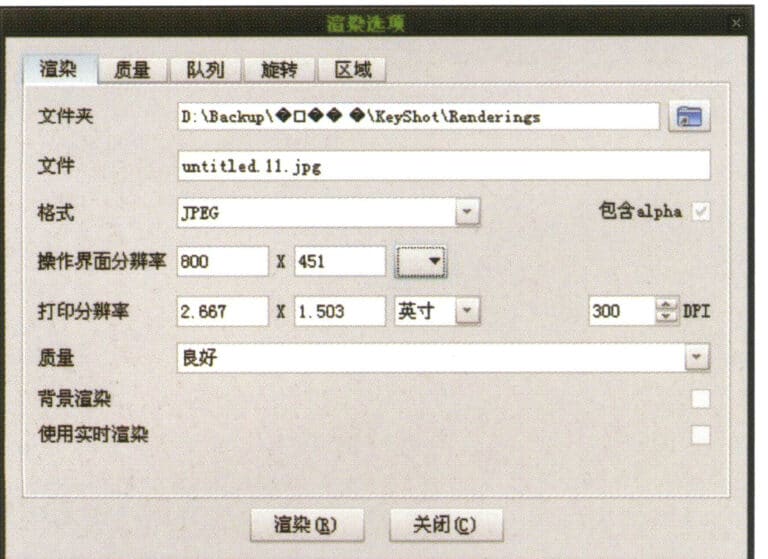
Set rendering size
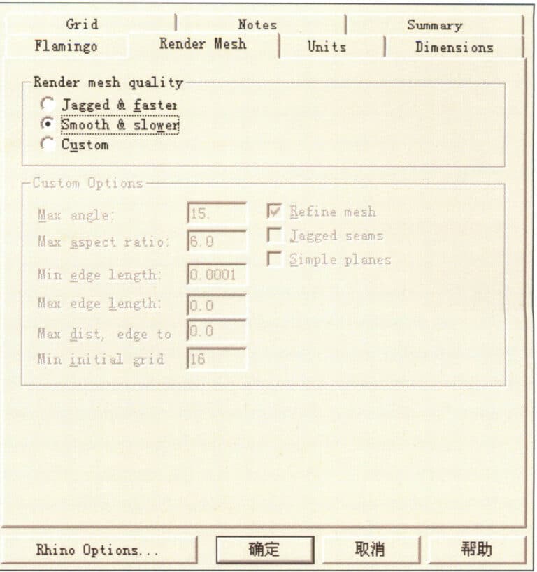
Set the smoothness parameters for the image
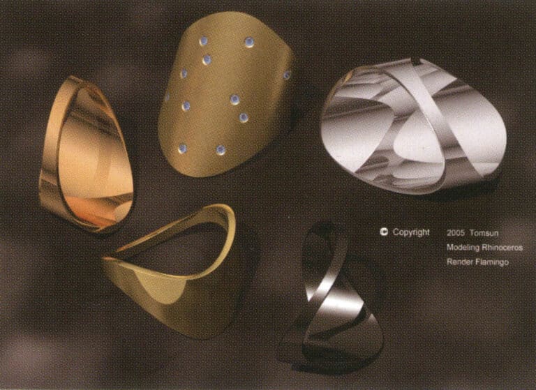
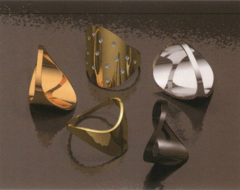
Final rendering
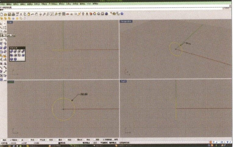
1. Open Rhino, select "Circle Tool," and draw a circular curve with a diameter of 6 mm on the Front plane

2. Select the curve that needs to be offset, long press "Curve Round Corner," then select "Offset Curve," input the required offset distance using the numeric keypad, press the stone key, and confirm.
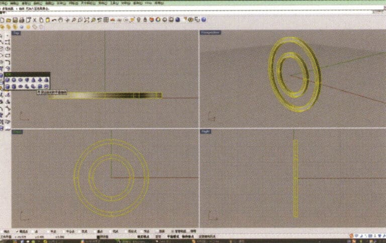
3. Select the four offset curves, long press , and choose "Solid Extrude," input the extrusion height using the numeric keypad and confirm, resulting in two ring-shaped solids
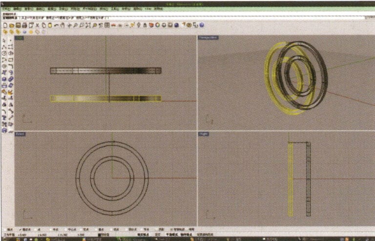
4. Select the two rings extruded in step 3, select “Duplicate”, enter the distance after duplication and confirm.
5. Select the circular curve with the largest diameter and use the "Offset Tool" to offset it to the middle of the upper and lower ring solids as a track
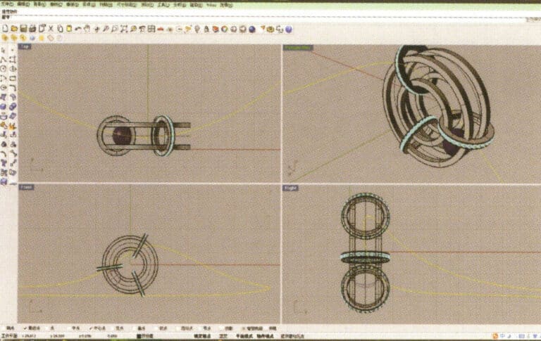
6. Select the curve as the trajectory, long press , and then long press to select "sphere, surrounding curve," check the capture command at the bottom of the window, then move the mouse to the desired drawing location, click the left button to confirm the position of the center, and then enter the radius of the sphere. After confirmation, the sphere is obtained
7. Similar to step 6, select the trajectory curve, long press , and choose "ring curve." Move the mouse to the center of the circle and enter the radius as prompted in the prompt bar to obtain the first ring curve, then select "offset" to get the second curve
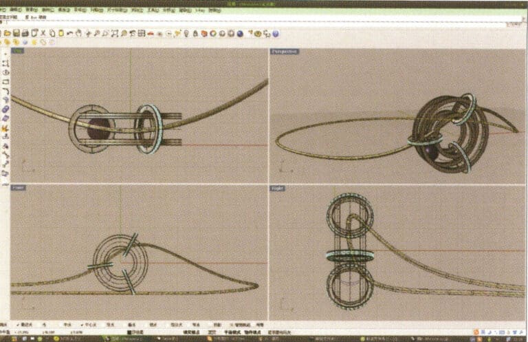
8. Select the two circular curves obtained in step 7, long press , and choose "Extrude," input the extrusion height using the numeric keypad and confirm while moving the circular solid to the center
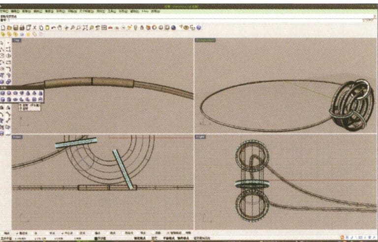
9. Select the previously created outer circular curve as the track, and choose tube to create a circular tube
10. First select the ring-shaped solid, then choose "Boolean operation difference," and then select the circular tube and confirm
11. Import the diamond model and move it directly above the groove created in step 10
12. Select the diamond, long press , and choose "Circular Array," then follow the instructions in the prompt bar at the top of the window to enter the number of arrays and confirm
13. Select the annular surface and diamond obtained in step 12, and long press

14. Select "Mirror" for the chives, check the "Capture Command - Center Point" at the bottom of the window, and after determining the center point, perform the mirror operation using that center point
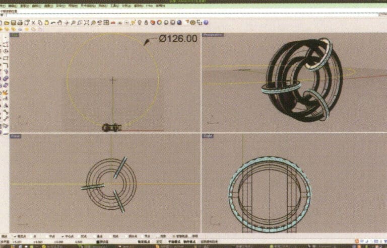
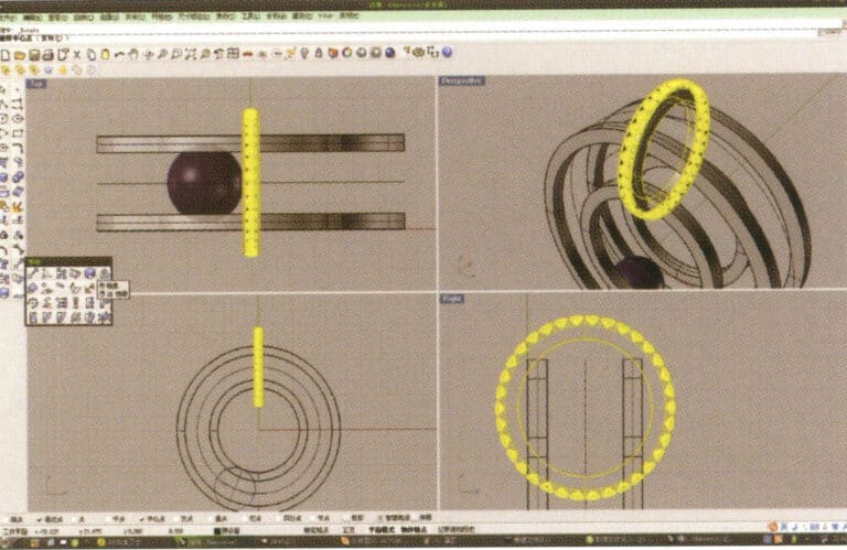
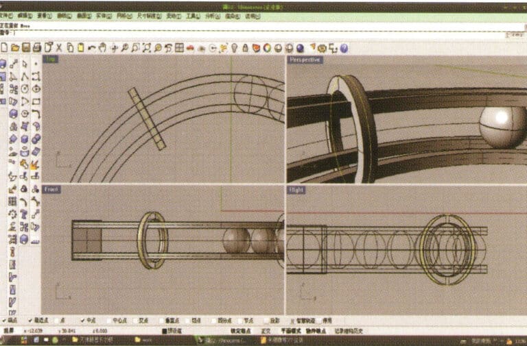
15. Select "Circle Tool" and draw a circular curve with a diameter of 126 mm on the Top plane
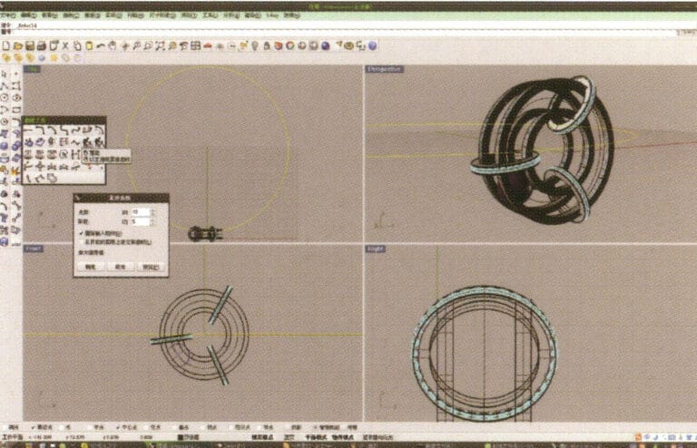
16. Select the curve obtained in step 14, choose "Rebuild," enter 10 in "Point Count," enter 5 in "Degree," and confirm
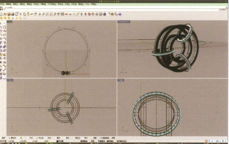
17. After confirmation, select the curve and press "F10" to display the 10 control points created earlier
18. By selecting and moving control points, deform the curve and make it pass through the two small rings
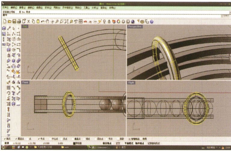
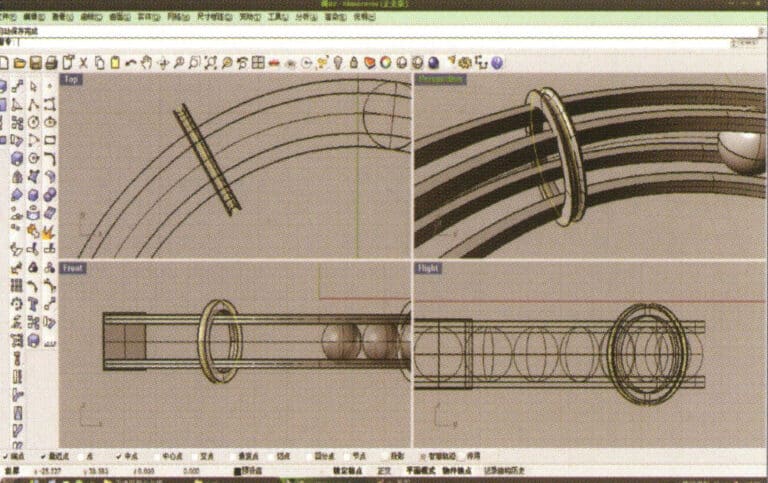
19. Choose the deformed curve as the track, and select "circular tube" to create a radius of 0.5 round tube
20. Use the same method as in step 18 to add details to the chain
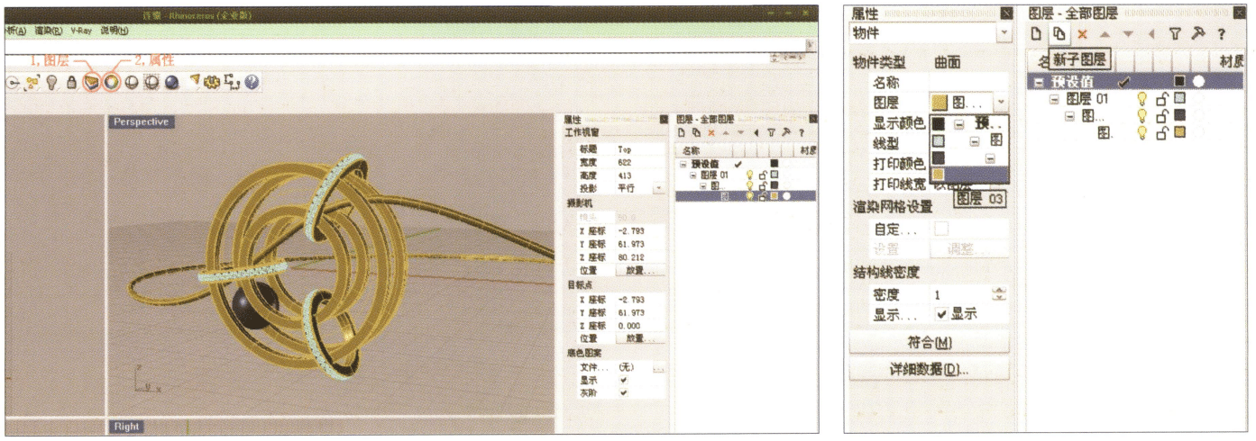
21. Select separately, first create a new layer in the "Layers" window on the right, then select the parts with the same material in the model, choose color layering in the "Layers" section of the "Properties" window, complete and save
22. Select "rendering software" for rendering, and after opening, directly drag the "Rhino model" into the Keyshot workspace
23. Open the "Material" library, select the desired material, and drag it directly onto the corresponding model part to start applying it. After completion, you can double-click the model to adjust the details of that part's material
24. After adjusting the material, environment, and view, you can select "Render" to adjust the rendering quality
25. Rendering completed
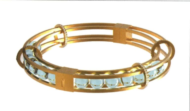
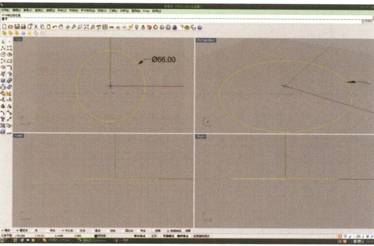
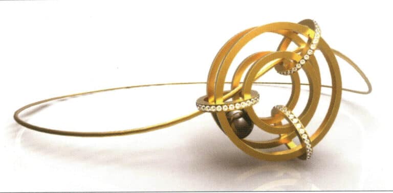
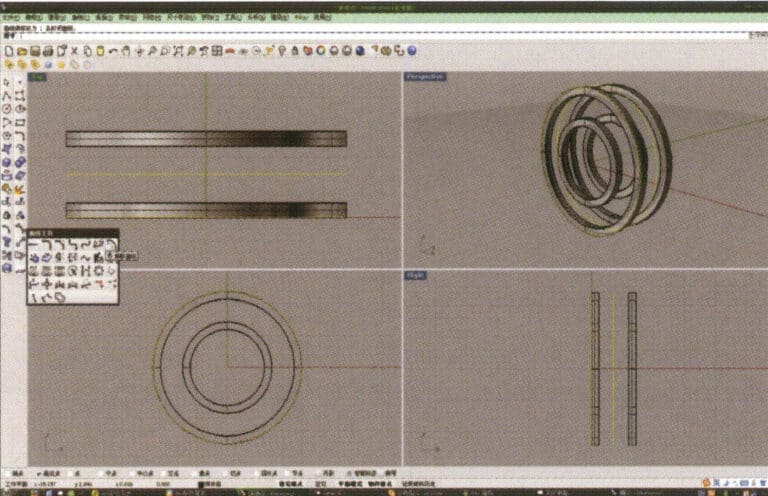
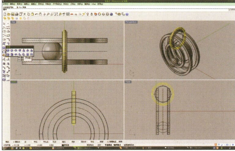
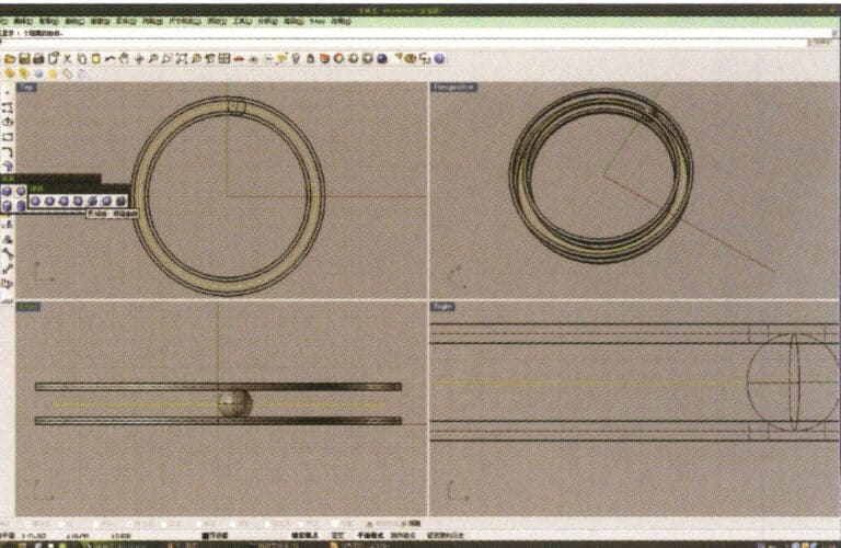
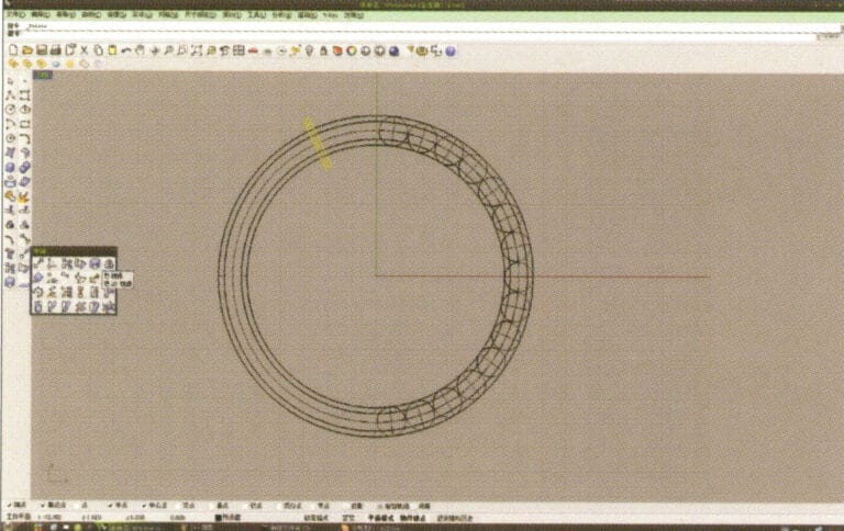
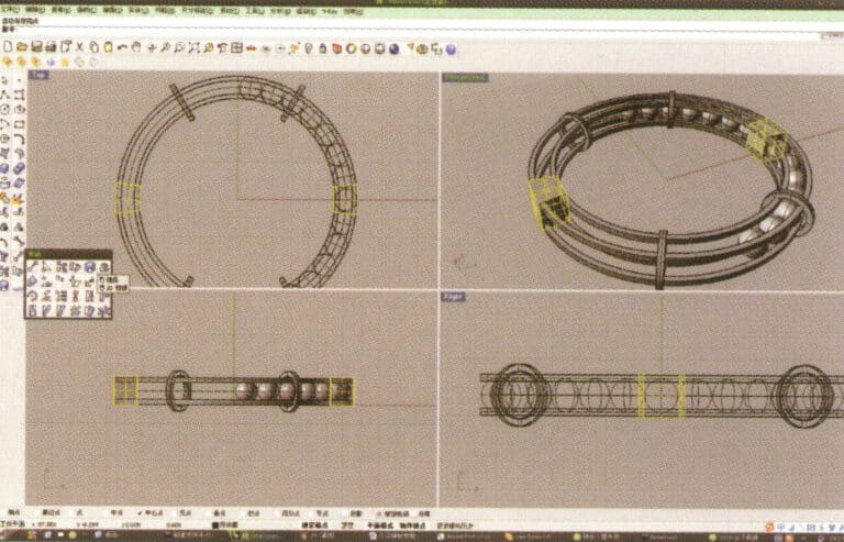
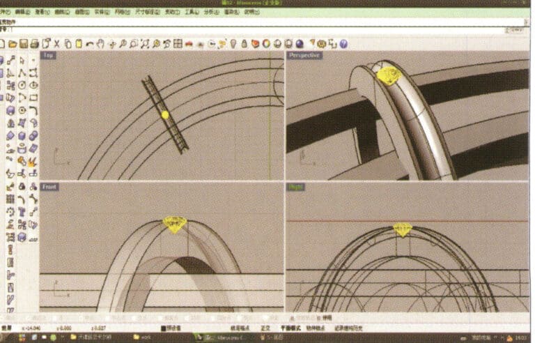
1. Open Rhino, select the "Circle Tool" and draw a circular curve with a diameter of 66 mm on the Top plane
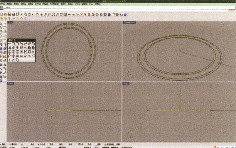
2. Select the curve that needs to be offset, long press "Curve Round Corner," then select "Offset Curve," input the required offset distance using the small keyboard, right-click, and confirm that the yellow curve in the image serves as the trajectory for the subsequent array of spheres
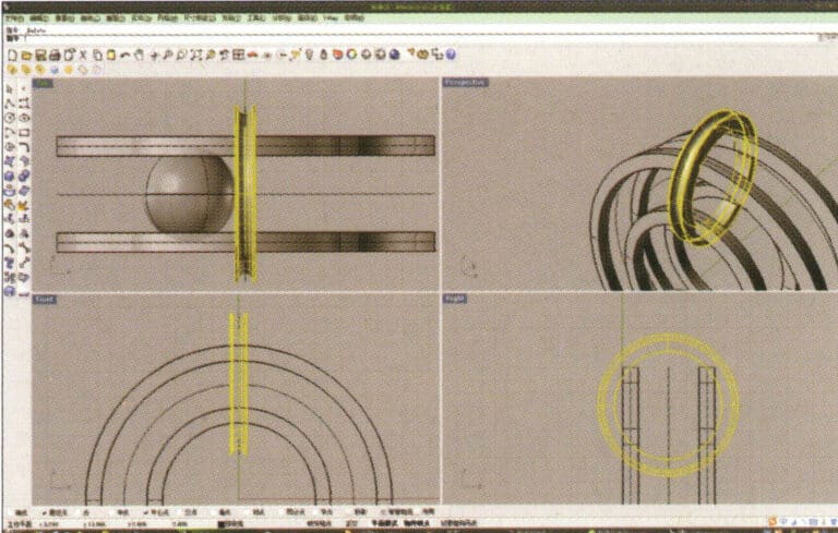
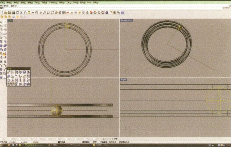
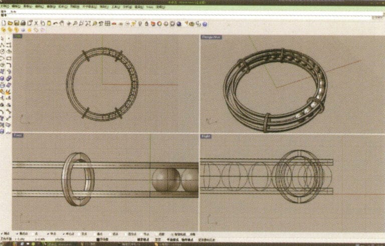
3. Select the two sets of curves to be extruded, long press and choose "Extrude," then enter the extrusion height using the numeric keypad and confirm

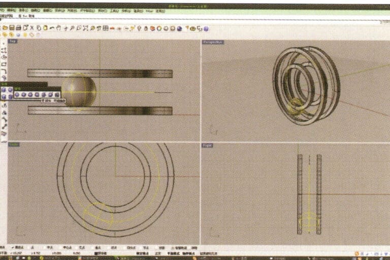
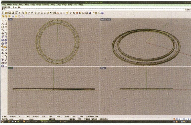
4. Select the two extruded surfaces from step 3, choose "Copy," enter the distance for the copy, and confirm; then select the curve used as the trajectory in step 2, and choose "Move" to move it up to the middle position between the two surfaces.
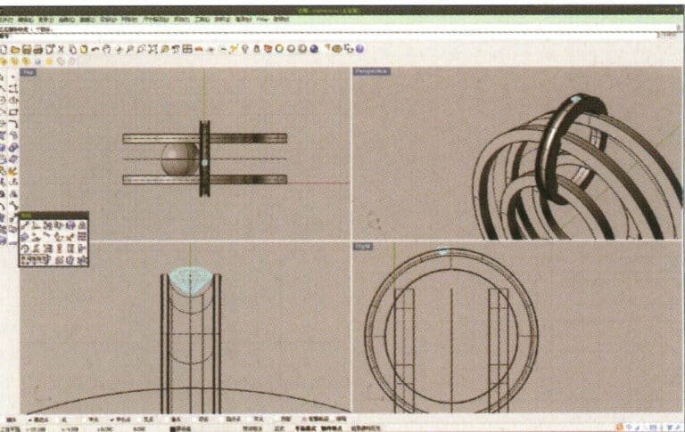
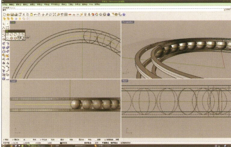
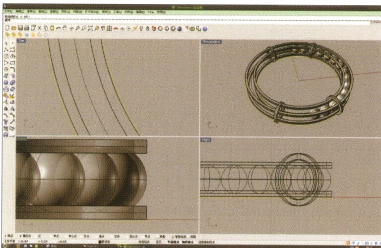
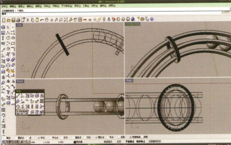
5. Select the curve as the trajectory, long press and then long press to select "sphere, surrounding curve," check the capture command "nearest point" below the window, then move the mouse to the location where you need to draw, click the left mouse button to confirm the position of the center of the sphere, then input the radius of the sphere, and after confirmation, obtain the sphere
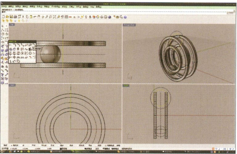
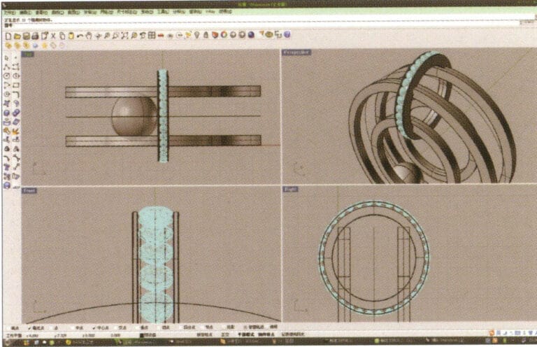
6. Select the sphere, long press and then select “Circular array”, and then follow the instructions in the prompt bar above the window, enter the number of arrays and confirm
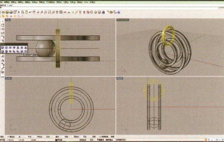
7. Similar to step 5, select the trajectory curve, long press , and then choose "ring curve." Move the mouse to the center of the circle and enter the radius as prompted in the prompt bar to obtain the first circular curve, then use "offset" to get the second curve
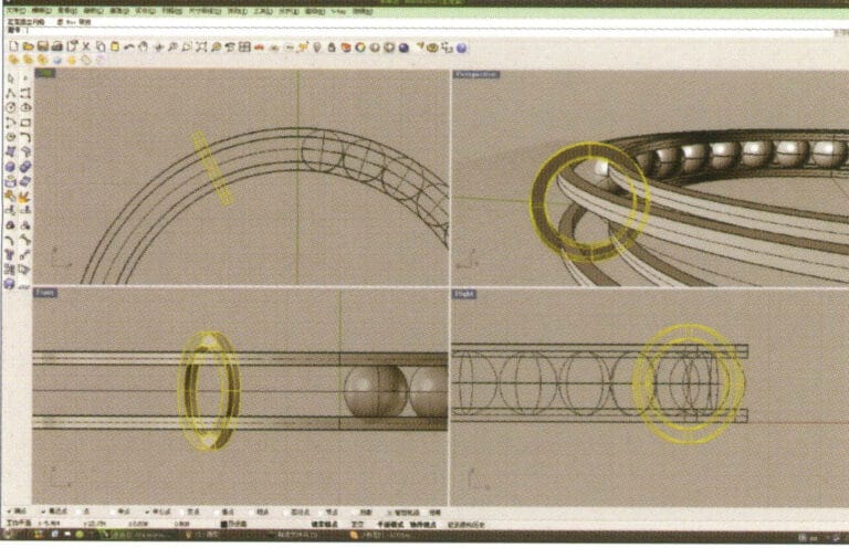
8. Select the two circular curves obtained in step 7, long press , and choose "Solid Extrude," enter the extrusion height using the numeric keypad and confirm
9. Select the annular surface obtained in step 8, long press then select "mirror."
10. Check the capture command for the center point below the selection window, and after determining the center point, use it for the mirroring operation
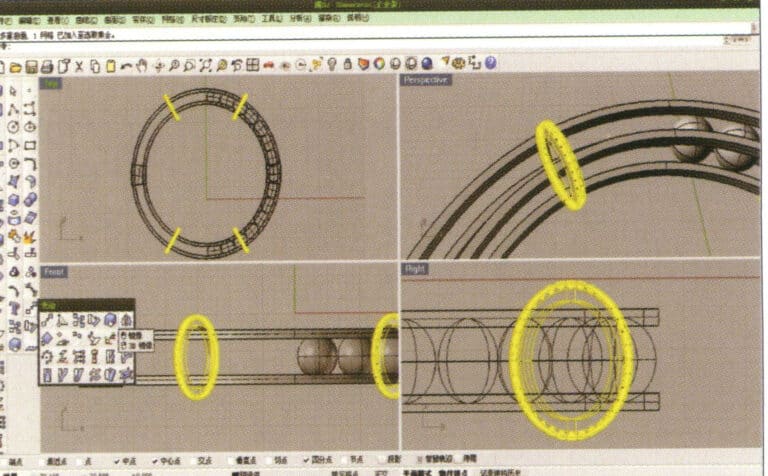
11. Select the outermost and innermost curves established initially and offset them one by one to obtain two new annular curves
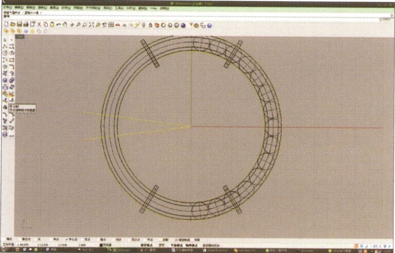
12. Create two straight lines, use "Split" to cut the two rings, and after completing that, use the resulting arcs to cut the two straight lines to obtain curves, then select and run to convert them into closed curves
13. Select the closed curve obtained in step 12 and extrude it, then mirror it
14. Select the edge curve of the circular solid, and choose "Offset Curve" to offset it to the center as the trajectory curve
15. Long press to select "cylindrical tube," input the radius to obtain the cylindrical tube
16. Select the small ring solid, long press to select "Boolean operation difference," then select the circular tube obtained in step 15, right-click and confirm (ring solid minus circular tube)
17. Import the diamond model and move it directly above the groove created in step 16
18. Select the diamond, then choose the "Circular Array Tool," and follow the prompts in the hint bar at the top of the window to input the number of arrays and confirm
19. Hold down "Shift," select all the diamonds after the array, and use the "Mirror Tool" with the center point as the center to mirror the diamonds into the other three ring-shaped entities
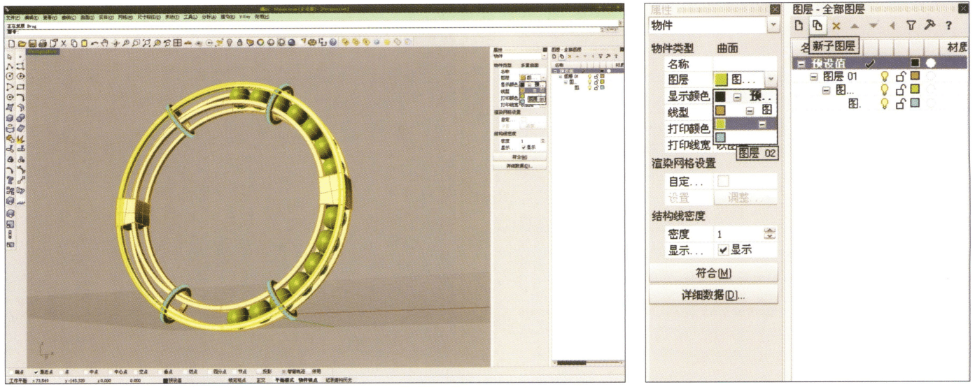
20. Select separately, first create a new layer in the "Layers" window on the right, then select the parts with the same material in the model, choose color layering in the "Layers" section of the "Properties" window, complete and save
21. Select "rendering software" for rendering, and after opening, directly drag the "rhinoceros model" into the Keyshot workspace
22. Open the "Material" library, select the desired material, and drag it directly onto the corresponding model part to start applying it. After completion, you can double-click the model to make detailed adjustments to that part's material
23. After adjusting the village quality, environment, and view, you can choose "render" to adjust the rendering quality

24. Rendering completed
Modeling: Rhino; Rendering: 3ds max; The scene applied HDR textures to simulate real natural lighting and set up realistic sunlight; The image shows the object reflecting the red effect of real sunlight
Modeling: Rhino; Rendering: 3ds max; The image simulates the effect of natural lighting, setting up the skylight, as if on open ground, influenced only by the environment of the ground and the effect of the skylight
Modeling: Rhino; Rendering: 3ds max; The scene uses only one high-intensity surface light source, and the texture of the gemstones is presented quite ideally; due to the high-intensity reflection of the metal surface, the coarse particles on the ground are also reflected on the metal surface
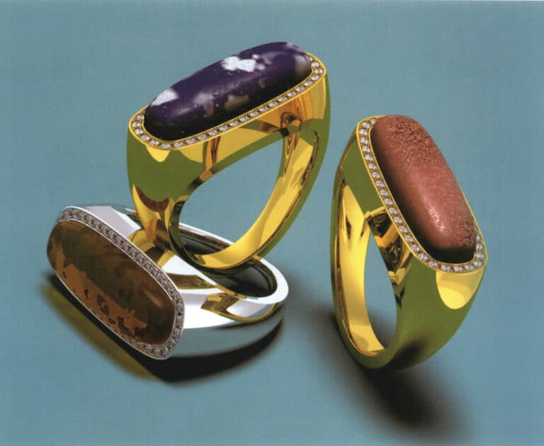
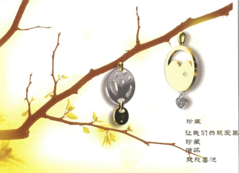
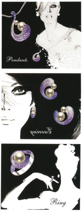
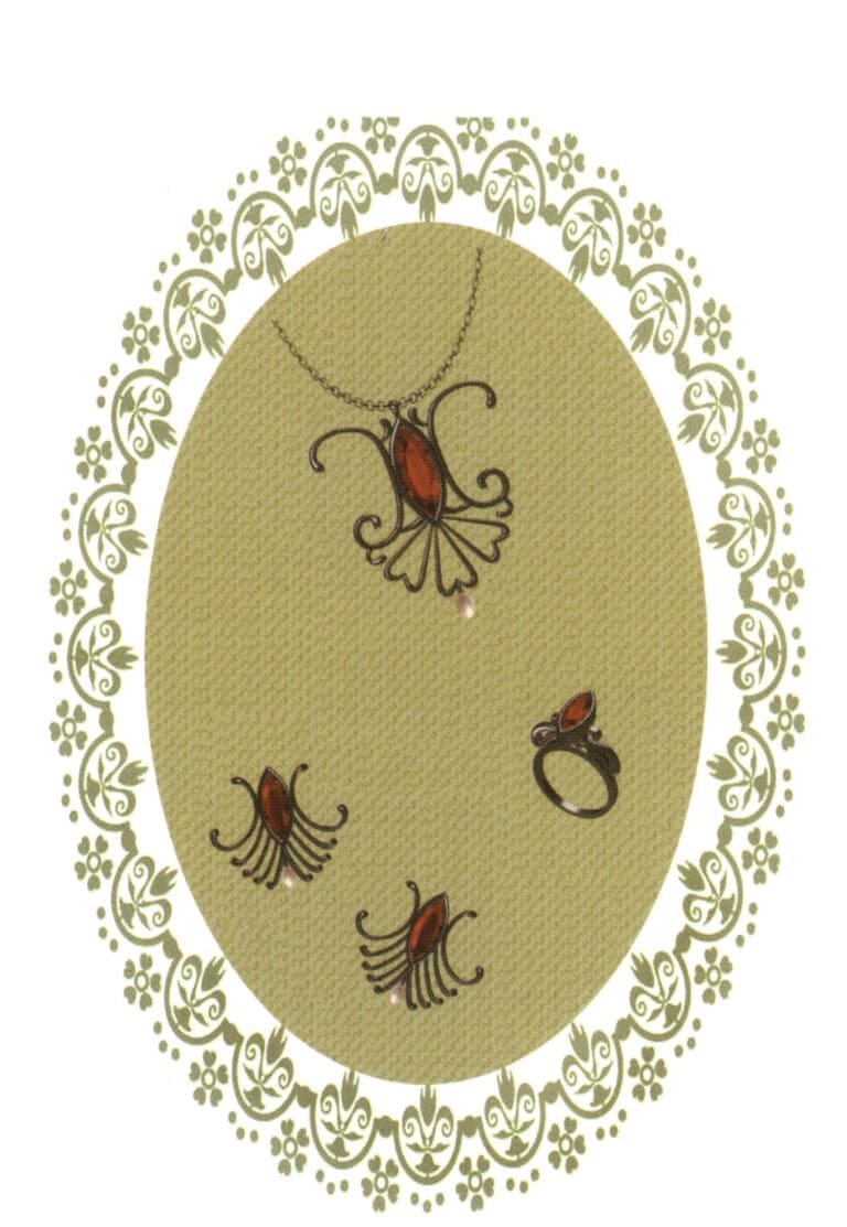
Modeling: Rhino; Rendering: Flamingo; Rich organic village textures (amber, coral, lapis lazuli)
Modeling: Rhino; Rendering: 3ds max; Simulating natural daylight and adding depth of field effects to mimic the perspective visual effects in real life; The implementation of depth of field relatively extended the rendering time
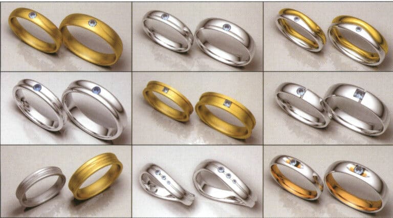
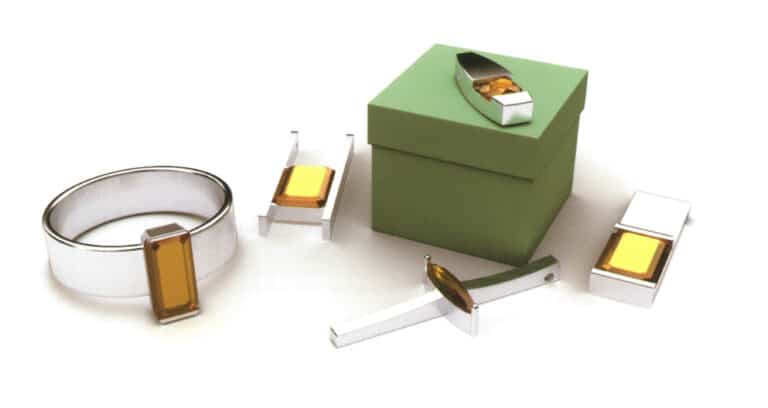
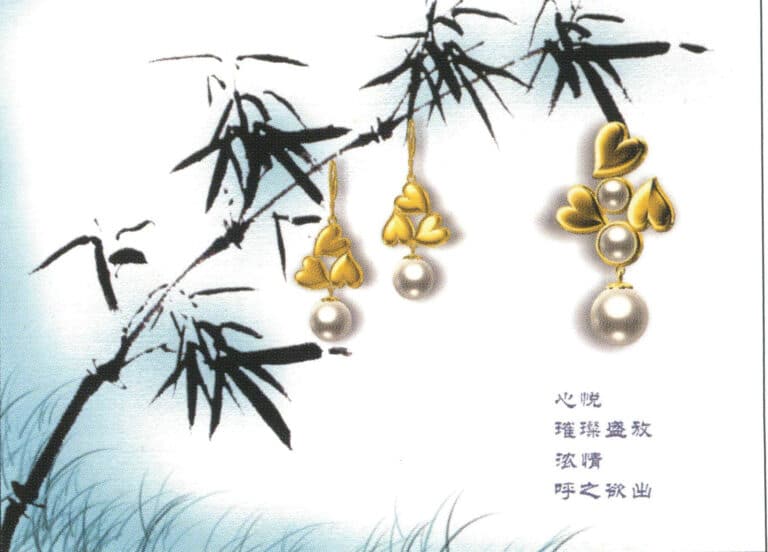
Modeling: Rhino; Rendering: Flamingo; Rendering of the wedding ring, different colored metal materials, special matte effect, observing the changes in light absorption and environmental reflection on the metal surface
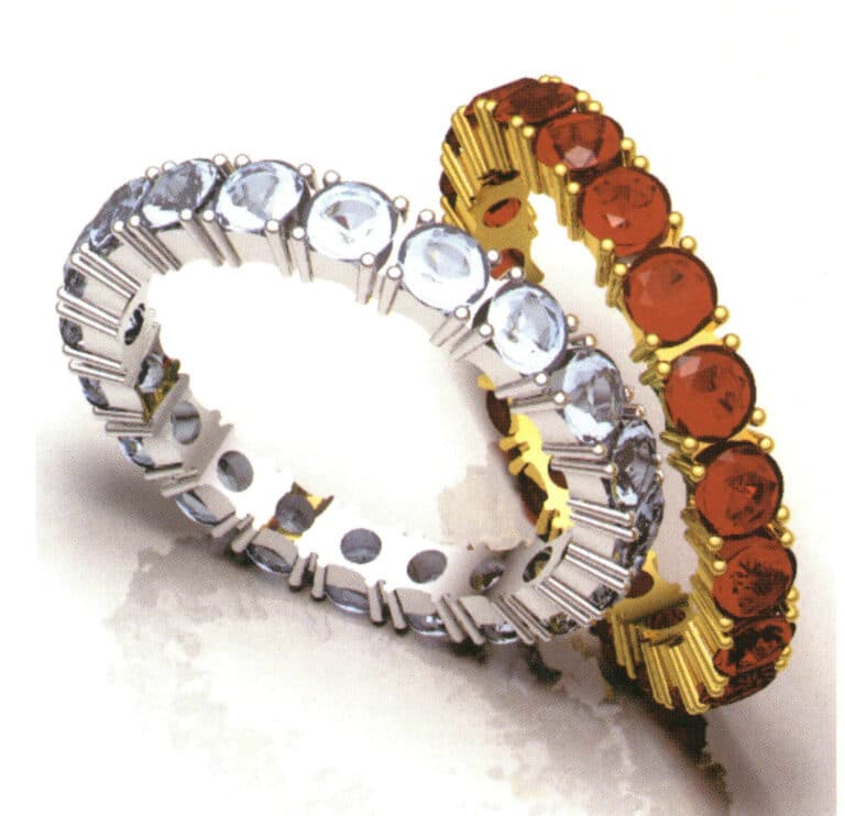
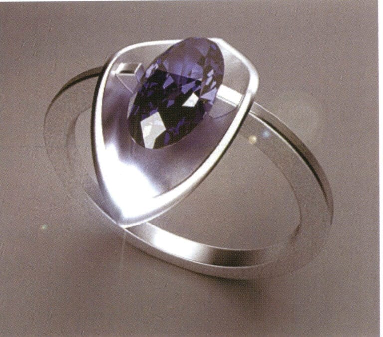
Modeling: Rhino; Rendering: Flamingo; Reasonably matches materials and renders the corresponding effects; Has the transparency effect of gemstone material

Modeling: Rhino; Rendering: Flamingo; The higher the quality of the NURBS surface of the object, the finer the image. Every detail must be strictly controlled during the modeling process.
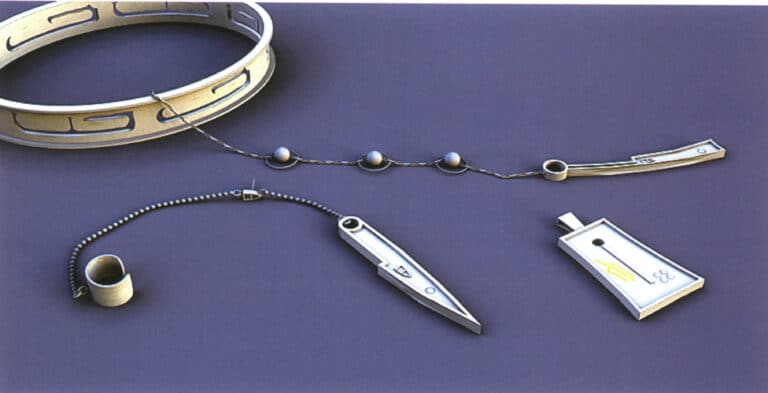
Modeling: JewelCAD; Post-processing: Photoshop; During the modeling process, pay attention to the angles and gaps between the repeated arrangement of components and enhance the texture of the metal and gemstones in post-processing
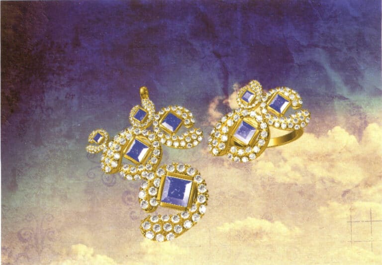
Modeling: JewelCAD; Post-processing: Photoshop; During the modeling process, attention should be paid to the variation in the curvature of cluster-set diamonds to ensure it is consistent with the curvature of the gemstones, as well as the connection between the metal parts of different setting methods
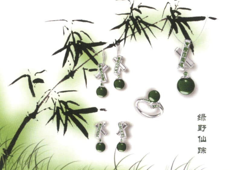
Modeling: JewelCAD; Post-processing: Photoshop. In the modeling process, we have to take into account the matching between the metal material and the gemstone material so that the whole design work has a better visual effect.
Modeling: JewelCAD; Post-processing: Photoshop; Pay attention to the change of light and shadow of the metal material, which can help to better express the sense of volume of the jewelry.
Modeling: JewelCAD; Post-processing: Photoshop; For more layers of jewelry, pay attention to the connection between the parts in the modeling process, which must be strictly in accordance with the structure of the jewelry to complete the metal part of the processing should pay attention to the changes in light and shadow
Modeling: JewelCAD; Post-processing: Photoshop; Selection of gemstone materials need to take into account the final modeling effect, pay attention to the contrast between light and dark metal and gemstone relations

Modeling: JewelCAD; Post-processing: Photoshop; For the representation of different metals, to fully reflect the color and texture differences of the metal
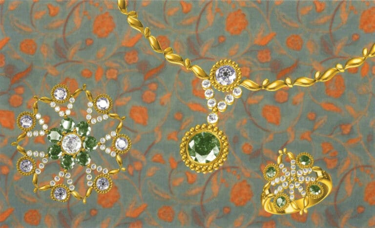
Modeling: JewelCAD; Post-processing: Photoshop. During the modeling process, attention should be paid to the fullness of the shape, and the combination of different colored gemstones should be applied to present a rich color effect.
Modeling: JewelCAD; Post-processing: Photoshop; During the modeling process, pay attention to the smoothness of the guide rails and the connection of different section profiles, making the design work natural and comfortable