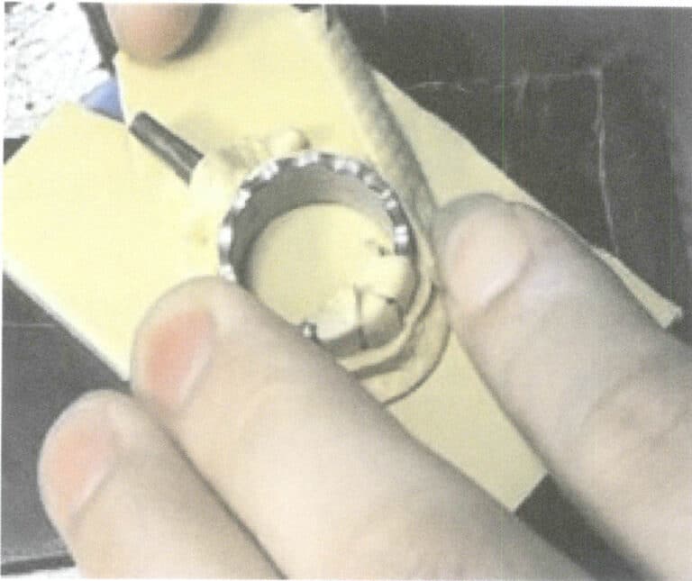
Что такое электроформование золота и как оно применяется к специальным материалам?
Understanding Gold Plating: Techniques, Benefits, and Applications
Введение:
Electroforming is an advanced electroplating-based manufacturing process that creates freestanding metal parts, primarily using gold and its alloys. Unlike conventional plating, it focuses on building thick, precise layers which are then separated from the substrate. The text explains how specific plating solutions and methods, like simultaneous or sequential deposition, are used to create complex gold alloy items such as decorative pieces and dental crowns. It also details why special surface preparations are crucial for plating challenging materials like stainless steel and titanium, addressing their passivation layers to ensure adhesion and functional performance in applications from electronics to aerospace.
what is electroforming of gold and how is it applied to special materials
Оглавление
Section I Electroformed Gold and Gold Alloys
Electroforming is a manufacturing process based on metal electroplating, which is different from electroplating aimed at coating materials. The difference in electroforming is that various methods separate the material after electroplating, and the product is only the metal electroplated layer. Although it may seem similar to electroplating, electroforming is more advanced and requires higher electroplating technology. Especially in terms of the plating layer’s current distribution and internal stress, it is more specialized than electroplating.
Since its inception, electroforming has a history of more than 100 years. In 1840, Dr. F. V. W. Netto first published a paper on electroforming, using copper plating solution to create dense copper replicas on flat or three-dimensional objects, modeling, similar models, printing, or casting.
Currently, the materials used in electroforming are mainly copper and nickel, with small amounts of additives added to high-concentration plating solutions for electroplating. The rise of electroformed gold has been a recent development, but truly ideal electroforming gold plating solutions do not yet exist.
1. Gold Plating for Electroforming
There are many types of plating solutions for electroforming. The commonly used plating solution is cyanide plating solution, while others include sulfite, chloride, or mixed solutions of these compounds. Generally, citrate plating solutions used for electroplating cannot be used for electroforming. Up to now, electroforming has still used the gold plating solution invented by Reid & Goldie (Table 1-118). These plating technologies have historical limitations and have certain practical issues. Rogers obtained a 100~125μm/h gold plating layer from a plating solution containing 14.1g/L potassium gold cyanide, 18.3g/L potassium cyanide, 14.1g/L potassium carbonate, and 11.4g/L boric acid under the condition of temperature 65℃, 3.2A/dm2 (however, according to electrochemical equivalent calculations, even if the current efficiency reaches 100%, only about 60μm plating layer can be obtained). In 1967, Japan and the UK obtained 7 kg of electroformed gold from a neutral plating solution (pH 6.5) of potassium gold cyanide containing 28~36g/L gold, neutralized with phosphoric acid.
In sodium, potassium, or ammonium ion type sulfite electroforming gold solutions, adding gold deposition grain refiners (DOS 2249658, 1972) containing arsenic compounds for electroforming can produce 600μm gold layer.
Table 1-118 Composition and Operating Conditions of Electroforming Solution
| Cyanide Plating Solution | Operating conditions |
|---|---|
|
1. Potassium gold cyanide Free potassium cyanide Dipotassium hydrogen phosphate Температура Current Density Stirring |
6. 8 〜 10g/L 31g/L 31g/L 50 〜 60℃ 2. 5 A/dm2 Cathodic stirring |
|
2. Potassium gold cyanide Potassium ferricyanide Potassium cyanide Температура Плотность тока |
30g/L 200g/L 7. 5g/L 85 ℃ 3 〜 5
|
|
3.Potassium gold(II) cyanide Potassium cyanide Turkish red oil Температура Current Density |
30g/L 70g/L 0. 5mL/L 60 〜 65℃ 0. 4 〜 1 A/dm2 |
|
4. Potassium gold cyanide Potassium cyanide Potassium hydroxide Potassium sulfamate
4-Hydroxy-3-methoxybenzaldehyde Температура Плотность тока |
18g/L 120g/L 4 г/л 4 г/л 4 г/л 80℃ 0. 5 〜 1. 8A/dm2 |
| Chloride Plating Solution | Operating conditions |
|---|---|
|
Gold (as chloride) Соляная кислота Sodium chloride Серная кислота Температура Current Density
|
25 〜 40g/L 23. 8 〜 55g/L 10 ~ 30g/L 10 〜 20g/L 23 ℃ 8. 6 〜 11. 0A/dm2 |
| Cyanide Chloride Plating Solution | Operating conditions |
|---|---|
|
Gold (as chloride) Potassium ferrocyanide Potassium carbonate Температура Плотность тока |
10 г/л 40 г/л 40 г/л 30 〜 50℃ 0. 1A/dm2 |
| Acid Plating Solution | Operating conditions |
|---|---|
|
Potassium gold cyanide Ethylguanidine Formic acid (85%) рН Температура Плотность тока |
30g/L 10 г/л 250g/L 4. 0 50℃ 0. 2A/dm2 |
| Cyanide-free plating solution | Operating conditions |
|---|---|
|
Sodium gold sulfite Potassium phosphate Sodium sulfite Arsenic trioxide рН Температура Плотность тока |
10 г/л 30g/L 50 г/л 30mg/L 9 〜 10 90℃ 0. 1 〜 0. 6A/dm2 |
| Alloy Electroplating Solution | Operating conditions | |
|---|---|---|
|
1.Au-Cu alloy plating solution Au (in the form of gold potassium cyanide) Cu (in the form of Na2Cu EDTA) Cu (in the form of Na2Cu EDTA) PO4-3 (in the form of 85% HPO3) Sodium sulfite рН Температура Плотность тока Precipitation rate Anode Alloying ratio of Au
|
(1) 6 〜 6. 5g/L 16 ~ 18g/L - 25mL/L - 7. 0 〜 7.5 65℃ 0. 6 〜 0. 6 A/dm2 10 〜 12. 7μm/h Платина 55% 〜 95%
|
(2) 6 〜 6. 5g/L - 16 〜 18g/L 25mL/L 6 〜 8mL/L 7. 0 〜 9. 0 65℃ 0. 6 〜 0. 6A/dm2 10 〜 12. 7/μm/h Платина 55% 〜 95% |
|
2. Au-Cu-Cd alloy plating solution Au (in the form of potassium gold cyanide) Cu (in the form of copper potassium cyanide) Cd (in the form of potassium cyanide cadmium) Ag (as potassium silver cyanide) Free potassium cyanide рН Температура Current Current density conditions for plating:Cathode current density Plating time Anode current density Plating time |
- 1 〜 3g/L 6 〜 13g/L 0. 1 〜 0. 8g/L 0. 01 〜 0. 1g/L 3 〜 8g/L 9 〜 11 60 〜8 0℃ PR Method(Cathode 60s, Anode 4s) 0. 5 〜 1. 5 A/dm2 4 〜 20s 1.0 〜 3. 0A/dm2 0. 5 〜 2s 18K Au-Cu-Cd Alloy Plating
|
|
2. Electroforming Methods
Common methods for gold alloy electroforming are: ① the simultaneous deposition method and ② the sequential deposition method.
(1) Simultaneous Deposition Method
This method involves alloy electroforming by depositing gold and 2 or 3 other metals simultaneously. The composition of the deposited alloy depends not only on the plating solution composition but also on current density and temperature. To maintain a certain alloy deposition ratio, the plating thickness must reach 100~300μm. When electroforming alloys, such as to ensure the consistency of the precipitation of electroforming 18K gold-copper-cadmium ternary gold alloy, the whole process of computerized management of electroplating is carried out in a way that the temperature of the plating solution and the concentration of metal ions are automatically controlled by sensors and the computer monitors the full current and the surface area of the product.
After electroplating the gold-copper-cadmium alloy electroformed layer must be heat-treated in an inert gas atmosphere. The investment in treatment equipment is very large (the composition of the plating solution is the same as the two types of gold alloy plating solutions in Table 1-118).
In recent years, due to environmental concerns about cadmium and the complexity of heat treatment, alloy components other than gold generally only use silver. Using the conditions in Table 1-119, gold-silver alloys from 8K to 18K are electroformed. Japanese patent Showa 58-130293 obtained gold-silver alloy electroplated layers with minimal composition variation and thickness of 150μm.
Table 1-119 Composition and Conditions of Plating Solution for Simultaneous Deposition Electroforming of 8K Gold-Silver Alloy
| Composition and Operating Conditions | Parameters |
|---|---|
|
Potassium gold cyanide Potassium silver cyanide Wetting agent Potassium cyanide Telluric acid pH Температура Плотность тока |
9g/L 4. 5g/L 1mL/L(partially esterified with phosphoric acid) 80g/L 2g/L(TeCl 4g/L, in the form of KTeO) 11. 0 40℃ 1,0 А/дм2 (100μm platable 100/μm 12K Au-Ag alloy plating)
|
US PAT. 3427231 by Lechtzin records experimental results, including the PR electrification method (cathode 60 s – anode 4 s). Swiss patent CH 529843 uses a PR method with a cycle ratio of 5 to 10 to 1.
US PAT. 3427231 describes the effect of using ultrasound in electroforming, where the current density can be increased to above 100A/dm2 , and by using ultrasonic stirring and filtration, additives can be avoided.
(2) Sequential Precipitation Method
This method causes the various components in the electroformed alloy to precipitate sequentially, with cycles ranging from one to several tens or hundreds of times. The precipitates form multilayers of different metals. After heat treatment of the precipitates, the metal components diffuse into each other to form a uniform alloy. Heat treatment is performed for alloying after electroplating a certain coating thickness using the plating solution and conditions in Table 1-120.
Table 1-120 Composition and Conditions of the Plating Solution for the Sequential Precipitation Method
| Composition and Operating Conditions | Parameters |
|---|---|
|
Au (as potassium gold cyanide) Ag (as potassium silver cyanide) Cu (as potassium copper cyanide) KCN Potassium bicarbonate pH Температура |
6g/L 0. 5g/L 35g/L 5g/L 100 g/L 9.0 60℃ |
| Using the above plating solution as the basic condition, vary the current density to repeatedly plate two types of alloys. After plating a 300μm two-layer composite coating, heat diffusion treatment of 800℃ for 30min, can obtain an 18K gold alloy of Au75%-Agl2%-Cul3%. | |
|
(1)Conditions for electroplating gold-silver alloy Current density 0. 5A/dm2 Thickness of the electroplated layer 0. 8μm(4min) (2)Conditions for electroplating gold-copper alloy Current density 1. 2A/dm2 Thickness of the electroplated layer 0. 64μm (4min) |
Composition of precipitates: Au 82% Ag 16% Cu 2% Composition of precipitates: Au 65% Ag 5% Cu 30%
|
The gold alloy plating obtained by this method has the following advantages:
① The composition of the gold-silver-copper alloy can be adjusted arbitrarily.
② The hardness of the gold-silver-copper alloy after heat diffusion is much higher than that of ordinary electroplated layers.
③ Good corrosion resistance. The gold-silver-copper alloy electroplated layer is not an alloy but a eutectic-plated layer. After heat diffusion, it is fully alloyed, with corrosion resistance equivalent to metallurgically manufactured alloys, significantly higher than gold-silver or gold-copper electroplated layers.
④ No use of gold-copper-cadmium alloy plating solution. The plating solution for the 18K layer contains no cadmium, making it environmentally friendly and safe.
3. Applications of Electroformed Gold
(1) Uses of Pendants and other Decorative Items
US PAT. 446421 Small hollow globe made by electroforming ball-shaped injection molded objects. After electroforming, small holes are made in the globe, and the plastic inside the globe is removed by heating to obtain a hollow metal sphere. This patented method involves sequentially electroplating copper, silver, gold, and other metals, followed by heat treatment alloying to produce the product.
GB PAT. 2031024 After electroforming real flowers, place them in an electric furnace for heat treatment for 24 hours, then use high-pressure water to blow from the top of the flower stem to remove residues, obtaining electroformed flower decorations.
Other patents, such as the Japanese patent (Showa 59-80788), detail the method of manufacturing gold alloy watch exterior parts using electroforming. The manufacturing method of gold pendants is shown in Table 1-121.
Table 1-121 Manufacturing Methods of Gold Alloy Decorative Items
| Шаги | Метод |
|---|---|
| Модель |
(1) Make decorations from paraffin according to the design, cast the model in silver, and finish it. Injection molding after making a rubber model out of a silver model (2) Casting the necessary number of models. At this time, we mainly use Pb-Zn-Bi alloy and Zn alloy (Zn96%-A14%). |
| Pre-treatment |
(1) Must remove the paraffin wax, metal substrate surface burrs and bumpy surface, otherwise affect the final quality of the product (2) When the material is paraffin, surface semiconducting must be carried out, there are the following two methods ① plastic plating, chemical copper plating metallization ② coated with conductive nitro lacquer, impregnated surface conductivity |
| Basic Plating |
(1) when the substrate is metal, polished and plated with acidic copper. The purpose is to plug the substrate on the sand holes, pores, etc. (2) For paraffin material, it is necessary to add a base layer of metal if gold is electroformed directly after conductivation. Since paraffin wax is watery at a melting point of about 70°C, the temperature of the plating solution must be ensured to be about 40°C. Otherwise, it is not possible to electroform gold directly on paraffin wax. |
| Electroformed gold |
The most commonly used plating solution is the Au-Cu-Cd alloy solution. The following is the alloy plating process Plating solution composition.: Au 6g/L Plating solution temperature 70℃. Cu 45g/L Current density 0.5~2A/dm2 Cd 1g/L Current efficiency 1.5A/dm2 , 1pm/min KCN 18g/L Composition of alloy:Au 5% pH 10 Cu 13% Cd 7% |
| During the electroplating of ternary alloys, changes in current density cause significant variations in current efficiency and the deposition ratio of gold, so it is essential to strictly control the metal concentration in the plating solution and the current density during electroplating. | |
| Post-processing |
(1) electroforming gold, must use nitric acid, hydrochloric acid and other inorganic acids to dissolve the alloy. After dissolution in the inert gas, 400 ~ 500 ℃, 30min heating treatment, to eliminate the internal stress in the product (2) Closed hole with gold alloy welding material |
| Fine finishing | Fine grinding of parts, the surface of the whole plating |
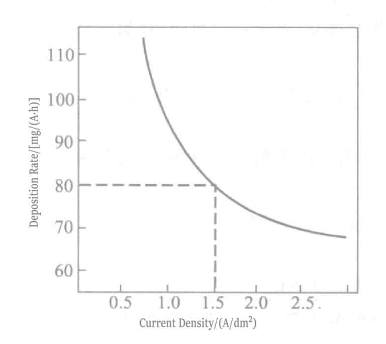
Figure 1-107 Relationship between current density and deposition rate
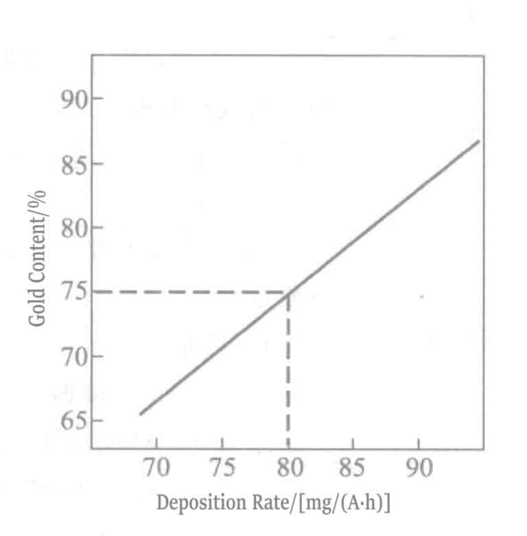
Рисунок 1-108 Взаимосвязь между содержанием золота и скоростью осаждения
(2) Dental Use
Dental crowns and prosthetic teeth have complex shapes and thin thicknesses, requiring high strength and corrosion resistance. Besides medicine, they also involve technologies from many other disciplines. Rogers, Vr-ijhoef, and others have proposed many research reports on these specialized technologies.
(3) Functional Purpose Detection Equipment
Functional testing involves equipment related to electronics, instruments, communications, and other fields.
X-ray Photomasks Nippon Patent Showa 58-224427
Nippon Patent Showa 58-200535
Infrared Filter Gratings G. Chanin
Spiral Micrometer Young Ogbum
Protruding pad lines US PAT.4125441
Spiral micrometers manufactured by the American Standards Bureau implement alternating gold and nickel plating. Since the thickness of the plating layer can be controlled and measured by the current, it can be used for the calibration of electron microscopes.
Section II Special Materials Gold Plating
1. Stainless Steel Electroplating
Due to a passive oxide film on the surface, stainless steel has excellent corrosion resistance. However, electroplating on the passive film of stainless steel is very difficult. Currently, a method with excellent precipitation bonding strength involves precipitating an ultra-thin nickel layer in an impulse nickel plating solution while activating the stainless steel, and the gold layer plated on the impulse nickel layer can be completely and tightly bonded. However, this method has significant drawbacks, severely reducing the corrosion resistance of stainless steel. The following are key issues in electroplating a corrosion-resistant gold layer on stainless steel.
① Do not use a nickel plating intermediate layer; directly electroplate gold on stainless steel.
② Do not use hydrogen halide acids to promote pore formation (hydrochloric acid activation is prohibited).
③ Ensure good adhesion.
To meet the above requirements, in 1971, the HAu(CN)4 manufacturing method and the HAu(CN)4 adjustment method of range of Plating solutions were developed. This plating solution works very well within the pH 0.1 ~ 3.0, consisting of gold ligands, citric acid, phosphate, or weak acids such as phosphoric acid.
In 1979, a method was started to flash gold plates (strike gold plating) on stainless steel using potassium gold(III) cyanide plating solution. Conductive salt potassium nitrate, ligand ethylenediamine hydrochloride, and alloy components such as nickel, cobalt, zinc, and indium were added to the plating solution, and it was used with pH controlled below 1.5.
Chlorine-free potassium gold(III) cyanide plating solutions were developed and widely used because the plating solution contained chlorine, which is unfavorable for stainless steel. These potassium gold(III) cyanide plating solutions were especially used for brush gold plating alloyed with cobalt (see Table 1-122).
Table 1-122 Flash Gold Plating Solution for Stainless Steel
| Composition and Operating Conditions | Параметр | Composition and Operating Conditions | Параметр |
|---|---|---|---|
| KAu(CN)4(calculated as Au) | 2 г/л | pH | < 0. 8 |
| Кобальт | 0. 2g/L | Температура | 35 ℃ |
| Серная кислота | 10mL/L | Плотность тока | 1. 5A/dm2 |
| Фосфорная кислота | 100mL/L | Plating time | 30 〜 60s |
Table 1-123 Corrosion Principles of Gold Plating on Stainless Steel
| Serial Number | Principle of Corrosion | Pitting Corrosion Diagram |
|---|---|---|
| 1 |
Stainless steel surfaces are prone to depressions during the activation process with high concentrations of hydrochloric acid. Defective areas such as depressions on the surface are responsible for promoting the formation of pores during gold plating. |

|
| 2 | As in the case of flash gold plating solution (1) containing chlorides, defects are generated on the surface of the chlorinated substrate. |

|
| 3 | In the case of gold flash plating using potassium gold cyanide [KAu(CN)4] phosphate solution, no dents are produced on the surface of stainless steel because hydrochloric acid and chlorides are not used. |
![In the case of gold flash plating using potassium gold cyanide [KAu(CN)4] phosphate solution, no dents are produced on the surface of stainless steel because hydrochloric acid and chlorides are not used.](https://sobling.jewelry/wp-content/uploads/2025/11/3.png)
|
There have been reports regarding the thin gold layer on stainless steel lead frames for ICs, concerning whether the weldability and wire bonding performance are good when the gold plating thickness is above 300Å(30nm), the welding performance is good around 450℃ 1min; When is it above 200Å, all gold wire bonding is good.
At this time, the thickness of the gold plating layer is 300Å, very thin. If the surface roughness of the stainless steel is coarse, it will affect the uniformity of the gold plating layer, resulting in defects such as pores. Therefore, in the activation treatment of the stainless steel surface, to smooth the surface and improve adhesion, inorganic mixed acids, and organic corrosion inhibitors can be used as treatment agents.
Besides corrosion resistance, gold and silver plating layers on IC stainless steel (SUS430) substrates are heated in an atmosphere of at 460℃, respectively 0s, 30s, 60s, 240s. Then, weldability and gold wire bonding performance are tested. Watt’s bath is used for strike nickel plating, and an intermediate plating layer is added to the nickel plating layer. When the outermost layer is gold plating, the silver plating layer and nickel-cobalt alloy plating layer as intermediate layers show better effects. When the outermost layer is silver plating, the palladium-nickel alloy plating layer (0.1μm) and electroless nickel plating layer (nickel-phosphorus, 0.1μm ) as intermediate layers show better effects. Or without intermediate layer, replacing the strike nickel layer with a strike nickel-cobalt alloy layer (0.02μm), can improve the heat resistance of the precious metal plating layer. The effect is especially significant when used as an intermediate layer for gold plating. This is because the nickel-cobalt alloy plating layer can act as a thermal diffusion layer for iron.
Копирайт @ Sobling.Jewelry - Пользовательские ювелирные изделия производителя, OEM и ODM ювелирный завод
2. Titanium and Titanium Alloy Plating
Titanium metal is light, with a specific strength (strength/density) twice that of steel. It has excellent corrosion and heat resistance in atmospheric and acidic environments, so it is widely used in the manufacturing of aircraft and aerospace industries. The standard electrode potential of the needle is E=-1.75V, more negative than aluminum’s, but it forms an oxide film in acidic environments and is easily passivated. The thickness of the passivation film reaches about 100Å, so it is difficult to achieve good adhesion when electroplating on titanium.
(1) Corrosion Methods
Research on electroplating sodium has reported about 33 cases from 1952. These methods all use corrosion to remove the oxide layer on the sodium surface, focusing on depositing the plating layer on the exposed activated surface. The summarized process flow from the literature is shown in Table 1-124, and various corrosion solutions are summarized by series in Table 1-125.
Table 1-124 Summary of Electroplating Methods on Titanium
| Серийный номер | Composition of etching solution | Operating conditions | Surface plating |
|---|---|---|---|
| 1 |
Ethylene Glycol HF |
Anodic etching 15 〜 30min |
Copper cyanide impact plating Copper fluoroborate plating |
| 2 |
(1) Ethylene Glycol 79% - HF 15% H2O2 6% (2) H3PO4 54% HF 12.5% NH4HF2 15. 5% H2O2 18. 1% (3) Ethylene Glycol 800mL/L - HF 200mL/L Zinc Fluoride 100 g/L
|
Anodic etching 55 〜 60min 5A/dm2 15 ~ 30min Anodic etching 3 ~ 5A/dm2 35 〜 45℃ 5 〜 10 min Anodic etching 0. 6 〜 1. 2A/dm2 25℃ 3 〜 10min
|
Copper cyanide impact plating - - - Copper cyanide impact plating - - - - Copper cyanide impact plating - - |
| 3 |
(1) Glacial acetic acid 875mL/L HF 125mL/L (2) Glacial acetic acid 875mL/L HF 125mL/L
|
Impregnation time 15min Cathodic corrosion 40 ~ 60Vcycle electrolysis - |
Copper Cyanide Plating Copper, Nickel Хром - |
| 4 |
Concentrated hydrochloric acid 1000mL - |
20 〜 40min 90 〜 100℃, 10 〜 15s
|
Direct impact nickel plating without washing - |
| 5 |
(1) Ethylene glycol 800mL/L - HF 200mL/L (2) Ethylene glycol 800mL/L - HF 200mL/L ZnF2 100mL/L
|
Cathodic corrosion 5A/dm2 Cathodic corrosion 20 〜25℃ - 6V 1 A/dm2
|
Copper, Nickel - - - Copper, Nickel - - |
| 6 |
(1) Sodium dichromate 390g/L HF 50mL/L (2) Sodium dichromate 250g/L HF 25mL/L (3) Sodium dichromate 250g/L HF 25mL/L CuSQ4 5g/L (4) CUSO4 225g/L HF 10mL/L
|
82 ℃ 20min 82℃ 20min 82℃ 1min - 93℃ 30s
|
|
| 7 |
Ethylene glycol 800mL/L - HF 200mL/L ZnF2 100mL/L -
|
4A/dm2、10min copper plating Anodic electrolysis 2A/dm2, 10min Cathodic electrolysis 50%、HNO3
|
|
| 8 |
Chromium fluoride 40g/L HCl 40mL/L
|
80 ℃ 3min
|
|
| 9 |
35% HCI 900mL/L 40% HF 100mL/L FeCl2 50 г/л
|
10 〜 15s 2 times impregnation -
|
Electroless nickel plating - - |
| 10 |
30% H2SO4 - - - - |
93℃ impregnation 2. 7 A/dm2 Anodic electrolysis 5 A/dm2 Cathodic electrolysis
|
Impact nickel plating - - - - |
| 11 |
- Chloroplatinic acid 0.5g/L Concentrated hydrochloric acid 100mL/L -
|
After washing with 5% tetrahydrate (combined) tartrate, plating in tetrahydrate (combined) tartrate copper plating solution | |
| 12 |
HF 200 〜 250mL/L HNO3 45 〜 50mL/L H2SO4 400mL/L
|
Impregnation 70 〜 80℃ 0. 5 〜 10min
|
|
| 13 |
NaF 100g/L HCl 100g/L Oxalic acid 50 〜 100g/L CTAB 0. 2 〜 10g/L
|
- Anodic electrolysis 30 〜 80℃ 0. 5 〜 10min
|
|
| 14 |
HNO3 45 〜 50mL/L Sodium oxalate 200g/L
|
70℃、5min - |
Alkaline nickel plating - |
| 15 |
(1) HF 130mL/L Glacial acetic acid 830mL/L HNO3 40mL/L (2) Concentrated hydrochloric acid 82℃ (3) CrQ3 • 6H2O 210 〜 250g/L - Concentrated hydrochloric acid 1L
|
- - - 82℃、Anodic electrolysis 10 ~ 50A/dm2 100℃、Anodic electrolysis 30 〜 100A/dm2
|
|
| 16 |
(1) HNO3 300mL/L HF 200mL/L Concentrated hydrochloric acid 100mL/L (2) Ethylene Glycol 750mL/L - HF 150mL/L - ⑶ CuSO4·5H2O 225g/L H2SO4 50 г/л Эл2(SO4)3 50 г/л Surfactants 1g/L Sodium dichromate 100g/L CuSO4 5g/L HCl 50mL/L
|
5min impregnation - Boiling impregnation cathodic electrolysis 5A/dm2 50 ~ 60℃ 5 〜 30min impregnation - - - 90℃ 1min impregnation -
|
Iron plating - - - - - - - - - - - - - - |
| 17 |
HF 200mL/L HNO3 45 〜 50mL/L - CrO3 HF -
|
Impregnation 25℃ 15min Impregnation 50℃ I 30min
|
Nickel sulfamate - Electroless nickel plating - - - |
| 18 |
Concentrated hydrochloric acid - |
Impregnation 3 min
|
After impregnation with tartrate tetrahydrate, plating in copper plating solution with tartrate tetrahydrate. |
Table 1-125 Composition of Various Etching Solutions
|
1. HF-HCl 2. HF-HCl-FeCl3 3. HF-HNO3 4. HF-CH3 COOH 5. HF-CUSO4 6. HF-CrO3 7. HF-Na2 Cr2 O7 8. HF-Na2 Cr2 O7 -CuSO4 9. HF-ethylenediamine 10. HF-ethylenediamine-ZnF2
|
11. HF-H3 PO4 -NH4 H F2 -H2 O 12. HCl 13. HCl-CrO3 14. HCl-CrF3 15. HCl-H2 PtCl6 16. HCl-NaCr2 O7 -CuSO4 17. HCl-NaF-oxalic acid-CTAB 18. H2 SO4 19. H2 SO4 -CuSO4 -Al2 (SO4 )3 -Surfactant 20. HNO3 -Sodium citrate
|
Table 1-126 Overview of Main Process Procedures and Test Results
| Нет. | Basic Process | Surface plating | Связывание | Comprehensive judgment | ||
|---|---|---|---|---|---|---|
| Appearance of plating | After bending | 480℃ 2h after heating | ||||
| 1 |
Etching (12%HF + 1%HNO3) 15min Anode (13%HF + 83%CH3COOH) Etching 40℃, 1.6A/dm2 6min
|
Nickel sulfamate 25μm
|
O | X | X | O |
| 2 |
Etching (5% HF + 40% HNO3) 15min Etching (10%HF + 10g/L CrO3) 30min
|
Electroless nickel plating 3μm
|
X | X | X | X |
| 3 |
Etching (10%HF + 70%HNO3) 15min 3min after boiling CONCHCI gas generation Copper cyanide impact plating 1min Impact nickel plating 3min
|
Electroless nickel plating 25μm
|
O | X | X | O |
| 4 |
Immersion etching (10%HF + 70%HNO3) 15min Anodic corrosion (10%HF + 70%HNO3) 5min Copper cyanide impact plating 1min Impact nickel plating 3min
|
Electroless nickel plating 30μm
|
X | X | X | O |
| 5 |
Etching (10%HF + 70%HNO3) 15min Boiling CONCHCl 10min Copper cyanide impact plating 1min Impact nickel plating 3min
|
Bright nickel 25μm
|
O | X | △ | △ |
| 6 |
Etching (10%HF + 70%HNO3) 15min With boiling CONCHCl 10min Impact plating with copper cyanide 1min Impact nickel plating 3min
|
Bright nickel 25μm
|
X | X | X | X |
| 7 |
Etching (Na2Cr2O7 + 60% HF) Impact nickel plating 3min
|
Bright nickel 25μm
|
X | X | X | X |
| 8 |
Etching (20% HNO3 - 20% Sodium citrate) - |
Alkaline Electroless Nickel Plating 10μm
|
O | X | X | X |
| 9 |
Anodic etching Glacial acetic acid 875mL/L HF 125mL/L Etching (same as above)
|
Bright nickel 25μm
|
O | X | X | X |
| 10 |
Anodic etching Ethylene glycol 800mL/L HF 125mL/L
|
Bright nickel 25μm
|
O | X | X | X |
| 11 |
Etching i Copper sulfate 200g/L Sulfuric acid 48g/L Aluminum sulfate 24g/L Etching ii Sodium dichromate 100g/L Copper sulfate 5g/L Hydrochloric acid 5mL/L
|
Bright nickel 25μm
|
O | X | X | X |
| NOTE: ○-favorable, △-general, ×-not good | ||||||
(2) Hydrochloric acid activation
After treatment with hydrochloric acid as an etchant, the surface of titanium appears as a black mesh pattern, and direct electroplating on it can also achieve good adhesion. The comparison results of the adhesion strength of the nickel plating layer in various process steps are shown in Table 1-127. Among them, the adhesion strength test results of the plating layer after heat treatment using process No. 3 are shown in Table 1-128. In the results, the boiling samples 1 + 1 HC1 were treated for 30min, 2 + 1HC1 treated for 15min, 2 + 1HC1 treated for 5 minutes, then electroplated with nickel. Afterward, the samples were heat-treated at 300℃ for 30 minutes and subjected to a bending test. The effect of 2+1was the best among them, indicating that heat treatment at 300℃ for more than 30 minutes is necessary.
Table 1-127 Titanium Electroplating Process Steps
| Процесс | 1 | 2 | 3 |
|---|---|---|---|
| 1.Organic solvent cleaning | O | O | O |
| 2.Alkaline degreasing | O | O | O |
| 3.Water washing | O | O | O |
| 4.Concentrated hydrochloric acid etching | O | O | O |
| 5.Water washing | O | O | O |
| 6.HF(46%) treatment | O | O | X |
| 7.Water washing | O | O | O |
| 8.Impact nickel anode electrolysis, 2.2A/dm2, 2min | O | O | O |
| 9.Impact nickel anode electrolysis, 2.2A/dm2, 2min | O | O | O |
| 10.Water washing | O | O | O |
| 11.Bright nickel plating | O | O | O |
Table 1-128 Relationship between Heat Treatment Temperature and Time of Electroplated Layer and Bonding Strength
| Heat treatment temperature /℃ | Heating time/min | |||||||||||
|---|---|---|---|---|---|---|---|---|---|---|---|---|
| 30 | 60 | |||||||||||
| 400 | O | O | ||||||||||
| 300 | O | O | ||||||||||
| 250 | X | X | ||||||||||
| 200 | X | X | ||||||||||
(3) Gold Plating
The gold plating process on the needle material is shown in Figure 1-109.

(4) Other Methods
After heat treatment of titanium material in the atmosphere, a stable oxide film is generated on the surface, and the oxide film is removed with a water-soluble reducing agent and a treatment solution that dissolves titanium, and then plated immediately. The process is shown in Figure 1-110.

First step treatment: 100~600℃ heat treatment for 50~60min.
Second step treatment: Activation treatment using an aqueous solution of water-soluble reducing agents (sodium hypophosphite, hydrazine, etc.) and salts that dissolve titanium (acidic ammonium fluoride, sodium fluoride).
Liu and others used a method to generate micropores on the titanium surface, where controlling the micropores’ number, size, and depth is very important. The process is shown in Figure 1-111. The relationship between the size, number of micropores, and the bonding strength of the coating is shown in Figures 1-112 and 1-113.

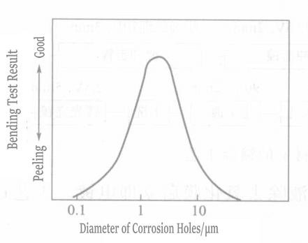
Figure 1-112 Relationship Between Pitting Diameter and Bond Strength
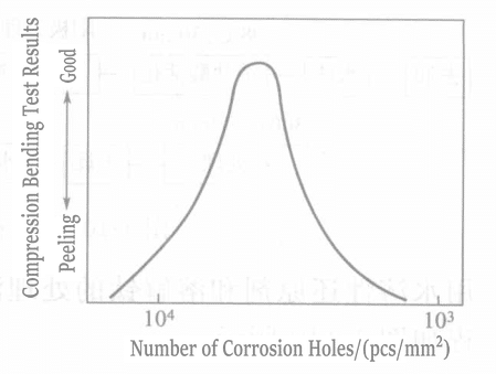
Figure 1-113 Relationship Between Number of Pits and Bond Strength
(5) Summary
The key to obtaining good adhesion of the gold plating layer on titanium material is as follows:
① Quickly remove the oxide on the titanium surface and immediately electroplate before oxidation occurs.
② The fixation effect of micropores generated on the titanium surface improves the bonding strength.
③ Heat treatment methods remove sodium from the surface and gases in the coating.


