Jewelry Quality Inspection And Defect Analysis
Of The Wax Lost Casting Process
Pendahuluan
The lost wax process is widely used in mass jewelry production, involving many methods, including making rubber molds, wax injection, wax tree setting, plaster mold casting, wax removal baking, and metal casting. Analyzing each step of the process reveals that each successful step is built upon the previous one, and any issues in the last step may affect the quality of the entire workpiece. This chapter mainly discusses three significant aspects of rubber molds, wax molds, and metal defects.

Daftar Isi
Section I: Rubber Mold Quality Inspection and Common Defects
As mentioned earlier, jewelry rubber molds are made of materials such as natural rubber, high-temperature vulcanized rubber, and room-temperature vulcanized rubber. Regardless of the type of rubber material used, it is necessary to follow the supplier’s guidelines and use appropriate tools and techniques to make the rubber mold. When a rubber mold has defects, it will inevitably affect the quality of the wax mold, so the rubber mold should be inspected before production.
1. Rubber Mold Quality Inspection Content
To evaluate the quality of a rubber mold should mainly be assessed from aspects such as rubber mold structure, inner cavity surface quality, rubber mold mechanical properties, and rubber mold process measures.
1.1 Mold structure.
When making and cutting the mold, the rationality of the mold structure should be considered to ensure accurate mold positioning and convenient demolding.
1.2 Mold cavity surface quality.
The inner surface of the mold cavity should be smooth and clean, without obvious air holes, adhesions, scratches, dust accumulation, and other defects.
1.3 Mold mechanical properties.
Including the elasticity, hardness, tear resistance, and other properties of the mold.
1.4 Mold process measures.
Including whether the pouring system and the setting of inserts are reasonable.
2. Common Rubber Mold Defects
2.1 Improper position of rubber mold cut
Analysis [Case 6-1]:
The mold is usually composed of two or more parts so that the wax mold can be removed from the mold. The joint surface of different mold parts is the parting surface, and a flash or burr will inevitably form at the parting surface. In this case, the parting surface passes through the centerline of the ring, creating a symmetrical mold in two halves. As a result, the wax mold will form a parting line at the top of the ring, increasing the workload of polishing and damaging the flatness and brightness of the surface.
Solusi:
In the jewellery lost wax casting process, when making wax molds with silicone rubber molds, it is not necessary to part from the most significant cross-section like with metal molds in order to demold smoothly, as silicone rubber molds are easily bent and opened. Therefore, to reduce the damage of the parting surface to the appearance of the workpiece’s front side, the parting surface is generally chosen at the edge of the ring, with most of the ring placed on one side of the mold.


2.2 Misalignment of Two Halves of Mold
Analysis [Case 6-2]:
When the mold is divided into two or more parts, positioning measures must be taken to ensure that the mold components fit together correctly and avoid misalignment issues. However, in this case, effective positioning measures were not taken, leading to mold misalignment issues.
Solusi:
When making the mold, the positioning method of the mold should be considered first, and sufficient space should be reserved when arranging the original version. There are generally two commonly used positioning methods for molds: one is the four-corner protrusion positioning, as shown in Figure 6-3; the other is the edge sawtooth mating line positioning, as shown in Figure 6-4.


2.3 No air vent hole is provided inside the rubber mold
Analysis [Case 6-3]:
During the wax injection process, the gas inside the mold cavity is driven forward along the wax direction of the flow. When it reaches the dead corner, it is hindered by the rubber mold wall, forming a filling back pressure, which may cause incomplete filling, air bubbles in the wax model, and incomplete formation of detailed parts. In the case of the ring, although air vents are opened in the middle of the side and claw, they are opened against the flow direction of the liquid, which is not conducive to gas discharge. Moreover, the air vent line at the claw position is opened in the middle, which does not have much effect on venting in the dead corner.
Solusi:
Only by smoothly removing the air inside the rubber mold cavity during wax injection without generating resistance to the wax filling can a wax model with precise contours be obtained. The rubber mold should not only have air vents but also pay attention to the location and direction of the vents. For the ring, in this case, adopting the air vent opening method shown in Figure 6-6 will effectively reduce the phenomenon of air entrapment.


The opening position of the vent line varies with different product structures. Still, the basic principle is the same: the vent line should be opened in the direction of the liquid flow at the dead corner, and its size should be controlled. Generally, only a gap is cut with a surgical knife, and sometimes, substantial vent slots may be blocked due to the influx of wax. Figure 6-7 shows the way the vent lines of some typical workpieces are opened.
2.4 Misalignment of the wax injection nozzle in the rubber mold
Analysis [Case 6-4]:
The wax injection nozzle in the rubber mold is a device used during wax injection to cooperate with the injection valve of the wax injection machine. Only when the two are closely matched can the wax flow smoothly into the rubber mold cavity. In this case, the wax injection nozzles in the rubber mold are pressed into the rubber layer separately, causing misalignment. Such wax injection nozzles will cause wax leakage during injection, affecting the quality of the wax mold.

The way to open the vent line in the rubber mold for jewelry pieces with different structures in Figure 6-7
Solusi:
The version of the two halves of the wax injection nozzle must have a positioning device, or the entire grain template can be embedded in the rubber layer, as shown in Figure 6-9.


2.5 The wax injection nozzle in the rubber mold is not smooth.
Analysis [Case 6-5]:
If the problem existed like this case with the wax injection nozzle in the rubber mold, that might cause the following issues: the nozzle will push the rubber mold open, causing a large amount of flash or incomplete filling; wax leakage during wax injection, the wax liquid injection is not smooth; wax injection may cause
The popularity of the body affects the quality of the wax pattern. Therefore, before wax injection, check the nozzle of the rubber mold. If there is an accumulation of wax material, impurities, etc., clean it first before injecting wax.


2.6 The rubber mold is soft and sticky.
Analysis [Case 6-6]:
The rubber mold must have good elasticity, cannot stick to the wax mold, and must have high tensile strength.
Otherwise, the details will not be precise, and the life of the rubber mold will be shortened. When the rubber mold becomes soft and sticky, it is mainly due to insufficient rubber vulcanisation, which is caused by short curing time or too low temperature. Therefore, it is necessary to appropriately increase the working temperature of the mold and extend the molding time.
2.7 The rubber mold is too hard, cannot be leveled.
Analysis [Case 6-7]:
When the rubber mold is too hard, it has high elasticity and cannot be leveled, and the two halves of the rubber mold cannot be closed together, as shown in Figure 6-11. making it easy to damage the wax mold when taking it out. This problem is mainly caused by excessive rubber vulcanization, which may be due to excessive mold pressure, prolonged vulcanization time, or too high vulcanization temperature:
Solusi:
Determine the appropriate vulcanization temperature, vulcanization time, and mold pressure based on the specific structure of the rubber mold. The vulcanization temperature and time of rubber basically follow a specific functional relationship, which is related to the thickness, length, width, and complexity of the first version of the rubber mold. Usually, the vulcanization temperature is set at around 150℃. If the rubber mold is three layers thick (about 10 mm ), the vulcanization time is generally 20 ~ 25 min. If it is four layers thick (about 13 mm ), the vulcanization time can be 30 ~ 35 min, and so on. Suppose the first version is a complex and small style. In that case, the vulcanization temperature should be reduced, and the vulcanization time should be extended (such as using the method of lowering the temperature by 10℃ and doubling the time). When filling the rubber, control the amount of rubber sheets reasonably so that after pressing into the mold frame, it is slightly higher than the frame plane by about 2mm.
2.8 The rubber layer peels off.
Analysis [Case 6-8]:
During the operation, if the protective film on the surface of the rubber sheet is removed prematurely and the bonding surface of the rubber layer is contaminated with oil from the hands, the rubber layer cannot fuse during vulcanization, causing delamination; spraying too much release agent, some of which immerse into the rubber material, causing delamination and cracking of the rubber layer; poor plasticity of the rubber material.
Solusi:
Choose a better plastic material for molding. It is necessary to ensure the cleanliness of the mold frame and raw rubber sheet. Before molding, clean the mold frame as much as possible, and the operator should wash their hands and the workbench. Do not directly touch the surface of the raw rubber sheet with your hands, but stick the raw rubber sheet and then tear off the protective film on the surface of the raw rubber sheet. Do not spray too much release agent when filling the glue.
2.9 The rubber mold is filled with pores and appears spongy.
Analysis [Case 6-9]:
There are several possible reasons for the rubber mold to produce pores or a spongy appearance:
(1) The rubber mold and aluminum frame are not tightly filled;
(2) The pressure is insufficient during vulcanization, and the gas and vulcanization volatiles trapped in the mold cavity cannot be discharged in time, so the pressure should be appropriately increased;
(3) Insufficient vulcanization, too low temperature or too short time, causing the volatiles generated during vulcanization due to the pores in the rubber mold shown in Figure 6-12 not to be removed entirely;
(4) Improper venting or lack of venting; air and moisture are trapped in the rubber material.
Solusi:
Use clean and dry adhesive material; Set exhaust slots in the mold frame. When filling the adhesive, use the plug, wrap, and fill method to fill the gaps, recesses, and stone inlays on the first version, ensuring there are no gaps between the raw adhesive and the first version. Set the vulcanization temperature and time correctly. In the initial stage of vulcanization, check if the heating plate is pressed tightly and tighten the handle to push the heating plate against the mold frame.

2.10 Tiny rubber threads in the rubber mold are prone to breakage.
Analysis [Case 6-10]:
Small holes are too small to rely on rubber threads; inserts need to be added.
Solusi:
Add a large pin as an insert and assemble it into the rubber mold, as shown in Figure 6-13. After wax injection, pull out the pin to obtain regular through-holes.

2.11 The inner cavity wall of the rubber mold is rough
Analysis [Case 6-11]:
A smooth inner wall of the rubber mold is an essential requirement to ensure the surface quality of the wax mold. When using a copper plate, it is easy to adhere to the rubber and affect the surface quality. During the wax injection process, in order to smoothly demold, a mold release agent or talcum powder is often sprayed in the rubber mold cavity. If talcum powder accumulates, it will cause roughness on the inner cavity wall of the rubber mold.
Solusi:
To ensure the inner cavity wall of the rubber mold is smooth.
Figure 6-14 shows the roughness on the inner cavity wall of the rubber mold.
To prevent adhesion between the original mold and the rubber, a silver mold must be used first. If using a copper mold, it should be silver-plated before molding. During wax injection, the amount of mold release agent or talcum powder should be controlled, and both should not be used simultaneously to prevent talcum powder from clumping and accumulating. Avoid frequent tapping of talcum powder, as tapping once generally yields 4-6 wax pieces of wax models.

2.12 The improper cutting method of the rubber mold makes it challenging to de-mold
Analysis [Case 6-12]:
In this case, the contour of the concave part of the ring is significantly larger than the opening part. During the process of removing the wax mold from the rubber mold, the wax mold is difficult to remove due to obstruction, and forcibly demolding can easily cause the wax mold to break or deform.
Solusi:
When cutting the rubber mold, consider whether it is convenient to remove the wax mold. In general, rubber molds it is often cut open at intervals, which is conducive to ventilation and facilitates demolding after the rubber mold is bent. For workpieces where the contour of the concave part is significantly larger than the opening part when cutting the rubber material of the concave part, a peeling cutting method can be adapted to pull it out from the inner cavity using the elastic deformation of the rubber strip, as shown in Figure 6-16.


Section II: Quality Inspection and Common Defects of Wax Models
3. Quality Inspection Content of Wax Models
The quality of wax patterns directly affects the final quality of jewellery. Paying attention to the quality of wax patterns is crucial. Unqualified wax patterns are not allowed to be used for wax tree planting, which can reduce unnecessary production and processing costs as well as precious metal losses.
Evaluating the quality of a wax pattern involves the following aspects:
3.1 Shape and size.
The wax pattern should accurately reflect the original shape, have no apparent deformations, meet the size requirements, not soften or deform easily, and be easy to weld.
3.2 Appearance quality.
The wax pattern surface should be smooth, refined, and clean, without apparent surface shrinkage, cracks, wrinkles, blisters, or flashes.
3.3 Intrinsic quality.
Pola lilin harus padat, tanpa gelembung udara yang jelas di dalamnya, dan hanya meninggalkan sedikit residu abu ketika dibakar.
3.4 Mechanical properties.
The jewelry wax pattern should have good strength, flexibility, and elasticity, with sufficient surface hardness at room temperature to ensure no surface abrasion during the dewaxing casting process; the wax pattern should be able to bend without breaking when taken out of the rubber mold, and automatically return to its original shape after removal. The wax pattern should be securely welded to the wax core during tree waxing and not easily fall off.
4. Common Wax Models Defects
4.1 Excess wax flakes or burrs appear on the wax piece
Analysis [Case 6-13]:
Defect description: Excess wax flakes or burrs appear on the wax piece. If this defect is not removed, it will increase the cleaning workload of jewelry casting bad parts, increase the possibility of bad parts cracking, and increase the loss of precious metals.
The reasons for the wax mold to produce burrs may include the following aspects:
(1) The air pressure of the wax machine is too high.
Jewelry pieces are relatively delicate and require external force to be injected into the wax.4

Figure 6-17 Injecting wax into the rubber mold cavity on the wax mold generally uses compressed air, which is relatively simple. The pressure of wax injection depends on the air pressure. If the air pressure is too high, it may cause the rubber mold to expand on the parting surface, resulting in burrs.
(2) The wax temperature is too high.
The fluidity of the wax is closely related to its viscosity, and viscosity is mainly dependent on temperature. The higher the temperature, the lower the viscosity, the better the fluidity, and the easier it is for the wax to form burrs deep into the rubber mold knife marks.
(3) The clamping force on both sides of the adhesive mold is too small.
The mold is divided into two halves or multiple parts for opening. When waxing, they are assembled and clamped with plates to form a closed cavity on the upper and lower sides. If the clamping force is insufficient, the wax liquid is easily pushed open by the external air pressure, leading to a flash.
(4) The mold is not cut well, deformed, or has high elasticity.
When the mold is not tightly closed during molding, flash is inevitable.
Thus, corresponding measures should be taken:
(1) Reduce the air pressure of the wax machine, generally more plane wax samples, simple shape with 0.5-0.8kg/cm2 pressure; wax samples with thinner walls, set stone bit more and the gap bit narrow and thin with 1.0-2.0kg/cm2
(2) Properly reduce the wax temperature. For typical workpieces, controlling the wax temperature between 70 ~75℃ ensures the fluidity of the wax.
(3) Increase the clamping force on both sides of the rubber mold. When operating, please pay attention to the technique, use both hands to clamp the rubber mold in the clamp plate, and ensure that the fingers are evenly distributed to apply pressure to the rubber mold; align the water inlet of the rubber mold with the wax injection nozzle and push it in parallel, firmly press the wax injection nozzle, and keep both hands still.
(4) Check the cutting quality and deformation of the rubber mold. High-quality rubber materials are used to making the rubber mold, which has good anti-aging performance and can maintain good softness, tensile strength, and elasticity for a long time. Adjust the molding process parameters reasonably during molding, and do not use excessive molding pressure, molding temperature, and vulcanization time.
4.2 Incomplete or cold shut flow marks on wax parts
[Case 6-14] Incomplete or cold shut flow marks on wax parts, as shown in Figure 6-18.
Defect description: Some parts of the wax part are not completely formed, or there are cold shut lines, flow marks, delamination, etc.
Possible reasons for defects such as incomplete wax mold include the following aspects:
(1) The wax machine has low air pressure, the wax liquid lacks sufficient external driving force, the flow is blocked, the filling is slow, and when the liquid flow cannot merge.

(2) The wax liquid temperature is low; there is not enough overheating to maintain the flow of the wax liquid.
(3) The rubber mold is clamped too tightly. For some thin-walled workpieces, if the clamping force of the rubber mold is too large, the wall thickness of the rubber mold cavity will be reduced, increasing the difficulty of filling and forming.
(4) The wax nozzle of the wax injection machine is blocked, reducing the amount of wax liquid ejected and prolonging the time for the wax liquid to fill the rubber mold cavity.
(5) The rubber mold has a problem: the internal gas cannot overflow, forming a filling back pressure and hindering the smooth filling of the wax liquid.
(6) The rubber mold temperature is too low, absorbing a large amount of heat from the wax liquid, causing the flowing wax liquid to lose its fluidity quickly.
Solusi:
(1) Increase the air pressure of the wax machine, which is the most widely used method and more effective for workpieces with complex and delicate structures.
(2) Increase the temperature of the wax liquid. Without affecting the quality of the wax liquid, raising the temperature of the wax liquid will make it more fluid, maintaining its liquid state for a longer time.
(3) Properly reduce the pressure on both sides of the rubber mold. The rubber mold is relatively soft and elastic, and the clamping force used should not flatten and deform the rubber mold cavity.
(4) Clean and clear the wax machine wax nozzle. The wax injection valve nozzle is a small passage. Once the wax material is unclean and contains foreign impurities, it is easy to block it. The reused wax material must be filtered to remove impurities before reuse.
(5) Open ventilation lines in the dead corners inside the rubber mold so that gas can be smoothly discharged without generating filling back pressure.
(6) When the weather is too cold, preheat the rubber mold first to give it a specific temperature before starting the wax injection.
4.3 Air bubbles appear in the wax mold
[Case 6-15] Air bubbles appear in the wax mold, as shown in Figure 6-19.
Defect description: There are bubbles on the surface or inside of the wax piece, and the color of the bubble area is obviously lighter than the surrounding area under light. Whether the bubbles in the wax pattern affect the casting depends on the structure of the casting and the position of the bubbles. When the bubbles are exposed on the surface, it undoubtedly directly leads to holes in the casting at that position. When the bubbles are below the surface of the wax pattern, during the process of vacuuming the plaster mold, it is not ruled out that the bubbles in the wax pattern may burst under an external vacuum.
Possible reasons for the appearance of air holes in the wax pattern in the wax mold as follows:

(1) The wax machine pressure is too high. During the wax injection process, the wax liquid fills the mold cavity in a turbulent flow state, which may cause air entrapment and bubble formation.
(2) Need for more wax amount in the wax machine. When the wax liquid level is at the same level as or even lower than the wax outlet, the gas in the wax tank will be injected into the mold cavity along with the wax liquid.
(3) The wax liquid temperature is too high. At this time, the wax liquid absorbs a large amount of gas, which condenses and forms bubbles after cooling.
(4) The wax inlet of the rubber mold is not aligned with the wax machine outlet. When injecting wax, air enters from the side along with the wax liquid.
(5) The rubber mold does not have air vents, and they are blocked. When the gas in the rubber mold cavity cannot be smoothly discharged, it will wrap in the wax liquid or stay in dead corners, forming bubbles.
Therefore, corresponding solutions should be taken:
(1) Adjust the air pressure of the wax machine to ensure smooth filling and not too high.
(2) Increase the amount of wax in the wax machine so that the wax liquid is not less than 1/2 above the wax machine’s capacity.
(3) Adjust the wax temperature to the correct range.
(4) Align the wax injection nozzle of the rubber mold with the wax outlet of the wax machine and press tightly without leaving any gap.
(5) Open a vent line on the rubber mold, and regularly check the vent line to keep it clear.

4.4 Cracks or complete fractures occur in the wax models
[Case 6-16] Cracks or complete fractures occur in certain parts of the wax part, as shown in Figure 6-20.
Possible reasons for wax part fracture include the following aspects:
(1) More old wax needs to be reused in the cycle. The wax material is composed of paraffin, stearic acid, and various additives. Each time it is melted and injected, its performance will deteriorate, the elasticity and plasticity will correspondingly decrease, and the brittleness will increase.
(2) The wax piece is left in the rubber mold for too long before being removed. The brittleness of the wax piece is related to temperature. When the mold is taken at the appropriate interval after wax injection, the wax piece still maintains good softness at a specific temperature. When the temperature is too low, the rigidity increases.
(3) The use of inferior quality wax or wax that is too stiff results in poor toughness and easy breakage under stress.
(4) Improper cutting of the rubber mold makes demolding difficult.
(5) The operation technique for taking the wax mold is simple and rough.
Solutions:
(1) Reduce the amount of old wax used so that the new wax accounts for more than 60% of the total wax in the machine.
(2) When circulating wax in large quantities, inject a few fewer rubber molds at a time and promptly remove the wax molds when the molding time is up.
(3) Switch to high-quality wax or wax with a softer texture.
(4) Improve the way rubber molds are cut, and if necessary, further cut the obstructed areas of the molds.
(5) Be careful with the modulus operation.
4.5 Wax mold deformation
[Case 6-17] Wax mold deformation, as shown in Figure 6-21.
Possible reasons for wax mold deformation:
(1) Taking the wax piece out of the rubber mold too early after wax injection makes the wax piece have low deformation resistance and is prone to deformation.
(2) I am using wax that is too soft. Soft wax has low deformation resistance, especially in high temperatures, where deformation is likely to occur.
(3) The rubber mold is not properly aligned, causing misalignment and deformation after wax injection.
(4) The wax structure is unreasonable and lacks adequate support, making it prone to deformation during molding.
Solutions:
(1) After wax injection, the wax piece should be allowed to cool inside the rubber mold for a certain period before removal. For general jewelry pieces, wait for 1 minute. For thick-walled pieces, to shorten the molding time, the rubber mold can be immersed in cold water to accelerate wax solidification and cooling.
(2) Choose a harder wax. Temperatures vary by region and season. For high-temperature seasons, select wax with better resistance to softening and deformation.
(3) The rubber mold must be equipped with effective positioning devices, and the rubber mold must be appropriately aligned during waxing.
(4) For workpieces with fine cavities, support should be added to the master mold to improve the deformation resistance of the wax piece.


4.6 The wax mold surface is rough
[Case 6-18] The wax mold surface is rough, as shown in Figure 6-22.
Possible reasons for the roughness of the wax mold surface include:
(1)Excessive use of talcum powder or release agent during waxing. When the mold is not cleaned regularly, these substances will gradually accumulate, resulting in a rough surface of the wax piece.
(2) Using contaminated recycled wax. When granular substances are mixed into the recycled wax material, they will also be injected into the wax mold, forming dispersed rough areas. When these particles transfer to the surface of the casting, the result is even worse.
(3) The environment where the wax mold is placed needs to be cleaner; it is put for too long, and a large amount of dust is deposited on the surface.
(4) After wax repair, wax crumbs remain on the surface of the wax piece.
Solutions:
(1) Release agent or talcum powder should be used in moderation to avoid simultaneous use of talcum powder and release agent. Pay attention to inspecting the rubber mold during use and regularly clean the inner cavity walls.
(2) Ensure the quality of wax and clean reused wax before use.
(3) Maintain cleanliness in the workplace. When dust or residual wax crumbs deposit on the wax mold surface, clean them thoroughly.
Prepare the concentration of 0.2% – 0.3%neutral soap solution, wax mold first in the soap solution to wash, with a soft brush to remove the surface oil grey stains, and then clean with water.
4.7 The Wax models overweight
[Case 6-19] Wax part overweight
Many precious metal jewelry require controlling the weight of metal, which requires strict control of the wax piece weight. However, during wax injection, if the holding force of the rubber mold is insufficient or if the wax injection pressure is too high, the rubber mold cavity can bulge, as shown in Figure 6-23. There may be a flash at the parting line, resulting in overweight wax pieces.


Figure 6-23 Rubber mold bulges and deforms under excessive wax injection pressure, resulting in overweight wax pieces.
When manually holding the rubber mold for wax injection, different people or the same person in other states may have different holding forces. To maintain the stability of the wax piece weight, an automatic wax injection machine with a mechanical clamping device can be used, as shown in Figure 6-24. Place the rubber mold in the clamping device, enter the program number, and press the start button. It will be ready for injection.

The rear mold clamping, forward movement, automatic alignment of the wax injection port, vacuum, first wax injection, second wax injection, wax mold solidification retention, mold opening, and other actions are fully automatic. The temperature control is accurate, and the wax injection effect is perfect.
Thin-walled wax parts need to be formed with high wax injection pressure. In contrast, thick-walled wax parts require higher supplementary shrinkage pressure to compensate for the shrinkage of the wax parts, which is sometimes difficult to guarantee for the deformation resistance of the rubber mold. Therefore, for structurally simple wax parts, metal die casting can be used, which allows for very high injection pressure and good consistency in wax mold weight.
Section III: Quality Inspection and Common Defects of the Casting Mold Blanks
5. Quality inspection content of casting mold parts
The quality of the investment casting blank has a significant impact on the subsequent processing and finished product quality of jewelry. It is necessary to strengthen quality inspection in this process and classify the problems existing in the blank. For some significant or difficult-to-repair casting defects, it is better to judge them as waste in this process to minimize losses.
The quality inspection of investment casting blanks mainly focuses on the following aspects:
5.1 Appearance:
Periksa integritas blanko, apakah dimensinya memenuhi persyaratan, dan apakah ada cacat, seperti cacat, perubahan bentuk, retakan, dll. Periksa apakah warnanya memenuhi persyaratan.
5.2 Surface quality:
Whether the surface of the casting is smooth and dense and whether there are defects such as sand holes, metal wire holes, air holes, etc.
5.3 Intrinsic quality:
Whether the poured metal is correct, whether there are any wrong colors or insufficient colors, and whether mechanical properties such as hardness, strength, and formability meet the requirements.
5.4 Other aspects
include whether there is magnetism, whether it can meet the requirements for metal release, etc.
6. Factors affecting the quality of investment casting molds
There are many process factors involved in the jewelry investment casting process, all of which will have a direct or indirect impact on the quality of the investment casting molds. Many times, investment casting defects are the result of various factors accumulated throughout the process. The process factors involved fall into the following categories:
6.1 Physical and chemical properties of metal materials.
Including the overall composition of the alloy, the content and types of trace elements, the types and distribution of deoxidizers and grain refiners, the solidification range of the alloy, the ratio of new to recycled metal, the cleanliness of new and recycled metal, the heating history of recycled metal, the shrinkage characteristics of metal during solidification, the surface tension of metal liquid at casting temperature, the thermal conductivity of metal, the latent heat characteristics of metal, the wetting behavior of metal liquid on the mold, the thermophysical and chemical interactions between metal liquid and mold, etc.
6.2 Melting process parameters.
Including melting atmosphere, the humidity of the melting chamber, crucible shape, crucible composition, melting heat source, crucible life, crucible temperature, holding time of metal liquid at a specific temperature before pouring, standing time of castings after pouring, composition and condition of fluxes, etc.
6.3 Casting process parameters.
Including the thermal conductivity of the mold, the atmosphere of the mold cavity, mold temperature, mold structure, uniformity of mold temperature, permeability of the mold, mechanical strength of the mold, surface bonding strength of the mold, mold size, and shrinkage characteristics during mold pouring and cooling.
6.4 Pouring process parameters.
Including pouring air pressure, pouring head height, actual temperature of mold and molten metal, direction of molten metal flow relative to workpiece during casting, pouring speed in vacuum casting, size and shape of crucible outlet, rotation speed in centrifugal casting, distance between mold and crucible during centrifugal casting, time to maintain vacuum during vacuum pouring process, interval time from mold removal from calcination furnace to pouring, quenching time after casting solidification, method of plaster explosion, etc.
7. Common defects of investment casting molds
7.1 Porosity defects
Porosity defects formed by gas trapped in metal due to external or internal gas in molten metal, characterized by round or irregular holes, generally smooth inner wall of holes, color in metal or oxidation color, difficult to distinguish when accompanied by slag holes and shrinkage holes. Porosity affects the surface quality of castings, making it difficult to obtain a smooth and bright polished surface. Porosity reduces the effective cross-section of the workpiece, affecting the mechanical properties to a certain extent, and the degree of impact depends on the size and shape of the pores. According to the mechanism of pore formation, it can be divided into reactive pores, exudative pores, and entrained pores.
[Case 6-20] Reactive pores appear inside the casting.
Reactive pores formed by the chemical reaction of metal liquid with internal or external factors, generating gas, are called reactive pores. Reactive pores can be divided into two types: endogenous and exogenous. Endogenous reactive pores refer to the gas pores formed by the chemical reaction of metal elements or compounds dissolved in the metal liquid during solidification of the metal liquid, producing gas. Exogenous reactive pores refer to the gas pores formed by the chemical reaction of metal liquid with external factors such as mold, slag, and oxide film, producing gas. According to their characteristics, exogenous reactive pores can be divided into subcutaneous pores, surface pores, and internal pores.
To analyze the causes of reactive pores, one should first carefully observe the characteristics and locations where the pores appear. Suppose the pores are almost evenly distributed on the section of the workpiece, with a smooth inner surface. In that case, it indicates that the pores may not be generated by the decomposition of gypsum during casting but more likely by the metal liquid itself. For example, when reused materials containing gypsum investment powder are used, calcium sulfate in gypsum will decompose and release gas, and the copper oxide in the patch will react with gypsum to form gas, leading to the typical pores. If the pores are distributed only below the skin, the common reason is the decomposition of gypsum during casting. The presence of residual carbon will lower the decomposition temperature of gypsum, increasing the risk of generating reactive pores.
Taking the pores in Figure 6-25 as an example, the holes inside the yellow circles in the figure are smooth, typical pores. In contrast, the irregular holes marked with blue circles in the nearby area can be inferred to be particles that entered the cavity with the metal liquid after the mold peeled off. After being enveloped by the metal liquid, they decompose and react, releasing gas. Gas forms a large number of pores.

Solusi:
(1) If recycled materials are used, residual casting powder must be thoroughly removed as it will react with the molten metal to form gas. Waste castings with a large number of pores should be purified before remelting.
(2) The mold baking process should be thorough to eliminate residual carbon.
(3) Increase mold strength, reduce the impact of molten metal on the mold, and avoid peeling of the mold wall.
(4) Properly reduce the temperature of the molten metal and mold to minimize the risk of mold decomposition.
7.2 Pinholes with segregation in castings
[Case 6-21] Pinholes with segregation in castings, randomly distributed on the section of the casting, as shown in Figure 6-26.
Analisis:
Gas has a high solubility in high-temperature liquid; solubility decreases with the temperature drop, transitioning from liquid to solid, solubility sharply decreases, and undissolved gas precipitates. When the precipitated gas is not expelled in time and is enveloped by solidified dendrites, pinholes with segregation are formed.
Possible specific reasons include:
(1) The use of damp, oily metal materials.
(2) There is no protection during smelting or excessive gas absorption. Metal liquid quickly absorbs gas at high temperatures; the higher the temperature, the more serious the gas absorption is. After smelting, there is no effective degassing treatment of the metal liquid.
To solve the problem of pinholes with segregation, dry and clean metal materials should be used, the proportion of new and recycled metals should be controlled, attention should be paid to controlling temperature and atmosphere during smelting, and for metals that are prone to gas absorption, smelting, and casting should be done under a protective atmosphere as much as possible.


7.3 Entrapment porosity in castings
[Case 6-22] Entrapment porosity in castings, as shown in Figure 6-27.
Analisis:
Entrapped gas during the casting process, gas trapped inside the casting during solidification without escaping in time, forming porosity. Its characteristics are irregular distribution, mostly isolated distribution, and some pores are relatively large in volume. Possible reasons for the occurrence of entrapped porosity in castings include the following aspects:
(1) Splashing of molten metal during pouring from the crucible. In this case, the molten metal comes into contact with air on a large area, which not only quickly oxidizes but also inevitably entraps a large amount of gas.
(2) The casting sprue is set unreasonably, and the metal liquid channel needs to be smoother. When the casting sprue is designed in a closed manner, it is easy to cause turbulence and gas entrapment during filling.
(3) The pouring pressure is too high, and the metal liquid filling is unstable.
Solutions:
(1) Pay attention to the condition of the crucible mouth. If there are notches, nodules, damage, etc., repair and handle them before use. If they cannot be repaired, discard them.
(2) When setting up the casting sprue, consider the proportions of various sections. Use rounded transitions at the connection between the casting sprue and the casting to avoid necking down and prevent the phenomenon of gas entrapment caused by right-angle connections.
(3) Properly control the pouring pressure, such as the speed of centrifugal casting and the pressure head in vacuum casting, to ensure smooth filling of the metal liquid without splashing.
7.3 Shrinkage porosity defects
(1) Shrinkage of cast alloys. When a liquid alloy cools from liquid to solid state due to the gradual transition of metal atoms from short-range order to long-range order, as well as the reduction and disappearance of voids, a volume decrease generally occurs. After the liquid alloy solidifies, as the temperature continues to decrease, the interatomic distance shortens further, leading to a further reduction in volume. During the cooling process of cast alloys from liquid to solid state, a phenomenon of volume reduction due to temperature decrease is called the shrinkage of cast alloys. Shrinkage is the fundamental cause of many defects in castings, such as shrinkage cavities, shrinkage porosity, stresses, deformations, and cracks. It is one of the essential casting properties of cast alloys. It has a significant impact on castings (such as obtaining geometric shapes and dimensions that meet requirements, as well as dense, high-quality castings).
The volume change of an alloy, when it changes from liquid to room temperature, is expressed as volume shrinkage. In addition to being represented by volume change, the shrinkage of the alloy in the solid state can also be represented by length change, known as linear shrinkage. The shrinkage of the alloy goes through three stages: liquid shrinkage stage, solidification shrinkage stage, and solid shrinkage stage.
Liquid shrinkage: The shrinkage of a liquid alloy from the pouring temperature to the liquid line temperature at the beginning of solidification is called liquid shrinkage. Since the alloy is in a liquid state, it is called liquid shrinkage, manifested by the decrease in the liquid level in the mold cavity.
Solidification shrinkage: For alloys with a specific temperature range, when they transform from liquid to solid, it is called solidification shrinkage because the alloy is in a solidified state. The solidification shrinkage of such alloys mainly includes two parts: temperature decrease (related to the crystallization temperature range of the alloy) and state change (volume change during state change).
Solid shrinkage: The shrinkage of a cast alloy from the solidus line temperature to room temperature is called solid shrinkage because the alloy is in a solid state. In actual production, since solid shrinkage often manifests as a decrease in the external dimensions of the casting, a linear shrinkage rate is generally used for representation. If the linear shrinkage of the alloy is not hindered by the external bars of the mold, it is called free shrinkage; otherwise, it is called constrained linear shrinkage. The linear shrinkage of cast alloys not only directly affects the dimensional accuracy of castings but also is the fundamental cause of stress, cracks, and deformation in castings.
The casting shrinkage rate is not only related to the factors of the alloy used but also to the characteristics of the casting process, the structural shape of the casting, and the amount of dissolved gas in the alloy during the melting process.
Liquid shrinkage and solidification shrinkage are the primary reasons for the formation of shrinkage cavities and shrinkage porosities in castings.

[Case 6-23] The casting has shrinkage holes or surface shrinkage, as shown in Figures 6-28 and 6-29.
(2) Shrinkage cavities and shrinkage porosities in castings. During the cooling and solidification process of castings, due to the liquid shrinkage and solidification shrinkage of the alloy, holes often appear at the last solidified part of the casting. Holes with large and relatively concentrated volumes are called shrinkage cavities; holes that are small and dispersed are called shrinkage porosities. Shrinkage cavities have irregular shapes, rough surfaces, and developed dendritic tips so that they can be clearly distinguished from gas pores.
Suppose there are shrinkage holes and shrinkage in castings. In that case, the effective bearing area of the castings will be reduced, causing stress concentration, significantly reducing the mechanical properties of the castings, and also reducing the physical and chemical properties of the castings, damaging the surface density and polishing performance.
The primary reason for the formation of shrinkage is the same as that of shrinkage holes. It is mainly due to the wide range of crystallization temperatures of the alloy, the developed dendrites, the alloy liquid solidifying almost simultaneously, and the fine and dispersed holes formed by the liquid and solidification shrinkage not being supplemented by external metal liquid.
There is a certain regularity between the tendency of shrinkage and shrinkage in castings and the composition of the alloy. Directional solidification alloys tend to produce concentrated shrinkage; pasty solidification alloys tend to produce shrinkage, and the number of shrinkage holes and shrinkage can be converted into each other, but their total volume remains basically unchanged.

The above two images belong to the same type of shrinkage defect, and their formation process can be explained in Figure 6-30. After the metal liquid fills the mold cavity, a shell is formed on the mold wall due to the chilling effect of the mold wall; at the same time, volume shrinkage occurs, and the metal liquid level gradually decreases. As the heat of the metal liquid continues to dissipate to the mold wall, the solidification interface continuously advances into the liquid phase, the solidification layer becomes thicker and thicker, and the shrinkage cavities formed by the liquid phase and solidification shrinkage also become larger and larger. After solidification is complete, a pear-shaped shrinkage cavity is formed. If the riser does not provide enough metal liquid to fill this cavity
Then, shrinkage cavity residue will be left inside the casting, such as the shrinkage cavity in the ring handle shown in Figure 6-28. If the casting surface is an open flat plane, then the solidification layer on the surface, under the external atmospheric pressure and the low pressure or vacuum inside the shrinkage cavity, will form the shrinkage depression shown in Figure 6-29.


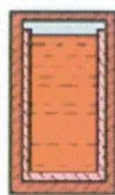

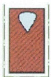

Figure 6-30 Formation process schematic diagram of shrinkage hole
Shrinkage holes have the following characteristics: Shrinkage holes often occur in cast alloys that solidify in a layered solidification manner, such as pure metals, eutectic composition alloys, and alloys with a narrow crystallization temperature range. They solidify in a layer-by-layer manner from the surface to the inside under general casting conditions; they are primarily concentrated in the upper part of the casting and the last solidified part; shrinkage holes also often appear in locations where solidification is later or slower, such as thick-walled areas of the casting, intersections of two walls, and near the inner sprue (referred to as hot spots). The shrinkage holes are relatively large, irregular in shape, and have rough surfaces.
[Case 6-24] Shrinkage porosity occurred in the casting, as shown in Figures 6-31 and 6-32.


In the above two cases of ring surfaces, hole clusters are visible to the naked eye, often occurring in large cross-sections, resulting in rough surfaces on the workpiece. When observed under a magnifying glass, a more apparent dendritic surface can be seen. When observed under a microscope, the inner walls of the holes are not smooth, showing a dendritic skeletal structure, as shown in Figure 6-33. Due to the appearance characteristics of such holes, this type of defect is widely referred to as “metal withering” in the jewelry industry.

Shrinkage, like shrinkage cavities, is also a hole defect caused by the contraction of the metal. Still, it has its characteristics in formation. The solidification of metal manifests as the nucleation and growth of crystals. For alloys with a specific crystalline spacing, their solidification is the process of forming crystal nuclei and growing crystals in a dendritic shape; especially for alloys with a wide range of crystallization temperatures, they generally solidify in a volumetric solidification manner. The tiny crystals in the solidification zone quickly develop into well-developed dendritic crystals. When the solid phase reaches a certain amount to form a crystal skeleton, the un-solidified liquid metal is divided into isolated small melt pools, as shown in Figure 6-34. During the subsequent cooling process, the liquid in the small melt pools will undergo liquid shrinkage and solidification shrinkage.
In contrast, the solidified metal will undergo solid shrinkage. Because the sum of the liquid shrinkage and solidification shrinkage of the melt pool metal is more significant than its solid shrinkage, the difference between the two causes small dispersed shrinkage cavities to form in the corresponding positions, namely shrinkage defects. Suppose the metal liquid does not wet the mold, and the gypsum decomposes to form sulfur dioxide gas. In that case, the remaining metal liquid will be pushed away from the surface, leaving behind a dendritic skeleton, thus producing a typical dendritic surface structure.
Possible causes and influencing factors of shrinkage cavities and shrinkage porosity
(1) Factors of casting alloys. Pure metals, eutectic component alloys, and alloys with a narrow range of crystallization temperatures tend to solidify in a layered manner, forming concentrated shrinkage cavities. By adopting appropriate casting processes, shrinkage cavities can be transferred to risers and cores to obtain dense castings. Alloys with a wide solidification range tend to solidify in a pasty manner, forming dispersed shrinkage porosity. When selecting alloys, alloys with a small solidification range should be used as much as possible.
When metal recyclables or severe oxidation occurs during the metal smelting process, it will promote the decomposition of gypsum investment powder, resulting in


Gas promotes the formation of dendritic crystal faces to a certain extent.
(2) Factors of the mold casting process. Mold temperature has a significant impact on shrinkage and looseness defects. A high mold temperature reduces the number of surface nuclei, which is conducive to the development of dendritic crystals. The surface solidification is fragile, promoting the formation of dendritic surface and shrinkage defects. Gypsum molds have poor thermal stability. When the mold temperature or metal liquid temperature is too high, it is easy to cause gypsum decomposition. Suppose the gypsum mold is not thoroughly calcined, and residual carbon appears on the mold wall. In that case, it will lower the gypsum decomposition temperature, increase the risk of gypsum decomposition, and further promote the formation of a dendritic surface.
(3) Factors of the pouring system: When the design of the pouring system conflicts with the solidification principles of the casting, it may lead to the occurrence of shrinkage or shrinkage porosity in the casting. The main manifestations are: the size of the core should meet the requirements of the entire metal tree for feeding and shrinkage and should maintain a certain height to facilitate sequential solidification; the size, quantity, position, and structure of chills have a significant impact on the solidification of the casting. Chills should be placed in the latest solidifying part of the casting, and their size and structure should ensure that they solidify later than the casting. The number of chills should ensure that they cover the entire feeding and shrinkage range of the casting; the position of the workpiece also affects the occurrence of shrinkage or shrinkage porosity. It should be a certain distance away from the sprue to obtain sufficient feeding pressure. The workpieces should not be too close to each other to avoid overheating the mold between the workpieces, leading to thermal decomposition.
(4) Factors of the pouring process. A sufficient amount of molten metal is a prerequisite for eliminating shrinkage porosity defects. The pouring temperature of the molten metal is susceptible to shrinkage and shrinkage porosity. Suppose the pouring temperature is too high; the liquid shrinkage of the metal increases. In that case, the cooling and solidification are slow, and the dendrites develop, which will significantly promote shrinkage and shrinkage porosity defects.
Micro shrinkage porosity is more likely to occur between dendrites, with small and curved holes dispersed throughout the entire section of the casting. It is difficult to avoid or eliminate when the feeding pressure is insufficient. Therefore, it is necessary to maintain the feeding and shrinkage channels of the core, chills, and molten metal to the casting, overcome the resistance along the way, and require sufficient external feeding pressure.
When wax trees are patterned, it is essential to avoid casting workpieces with significantly different structures on the same tree, as different structures require different casting processes, making it easy to encounter problems of neglecting one aspect while focusing on another when they are cast simultaneously.
(5) The aspect of workpiece structure. Shrinkage and looseness defects are also sensitive to the wall thickness of castings. Thick-walled castings are more prone to shrinkage and looseness, especially in components with thick cross-sections or central runners. The molten metal contains a large amount of heat, significantly increasing the temperature of the mold surface, raising the possibility of gypsum decomposition, and promoting the generation of gas shrinkage cavities (looseness). From this perspective, it is necessary to reduce the wall thickness of the casting. However, suppose the wall thickness of the casting is too thin, and the surface is too smooth. In that case, the probability of dispersed shrinkage defects increases. When the wall thickness of the casting is uneven, shrinkage cavities or looseness are easily generated at the thick wall parts and hot spots. Therefore, the wall thickness should be controlled within a specific range, the wall thickness difference should be minimised as much as possible, and measures should be comprehensively taken in terms of the number of casting sprues and its positions, mold temperature, molten metal temperature, metal properties, etc.
7.4 Surface roughness
Surface roughness refers to the uneven and rough surface of castings, generally caused by two situations: one is caused by the roughness of the master mold, and the other is caused by poor mold quality during the casting process.
[Case 6-25]
When using rapid prototyping wax patterns or resin patterns to cast silver patterns, there are usually tiny steps formed by laminated manufacturing on the surface of the wax patterns or resin patterns, which will be replicated on the surface of the silver castings, resulting in roughness on the surface of the cast silver patterns, as shown in Figure 6-35.


[Case 6-26] Casting 925 Silver Pendant Surface Rough, as shown in Figure 6-36.
The master mold surface is very smooth, but due to poor wax mold or casting mold quality and inappropriate casting process, a large number of pitting points appear on the surface of the casting bad parts, rough and uneven.
Analisis:
The surface roughness on jewelry castings is closely related to the quality of the master mold, wax mold, casting mold, and casting process. The possible reasons for the surface roughness of the casting parts are as follows:
(1) When the surface of the original or wax mold is rough, the castings made from it will definitely be rough.
(2) The casting mold has poor strength and is prone to cracking and peeling. For example, low-grade casting powders, prolonged storage of casting powders without use, storage of casting powders in a humid environment, and excessively high water-to-powder ratio during opening powder will all reduce the strength of the casting mold.
(3) When the wax tree is planted, if the welding parts are not adequately treated, sharp angles or small holes appear, and the casting mold may crack due to the impact of the poured metal.
(4) During casting, the metal liquid brushes against the mold wall, causing the mold wall to crack and peel. The faster the metal liquid filling speed, the greater the brushing force on the mold and the greater the risk of casting powder particles peeling off. Centrifugal casting is more likely to form such defects than static casting.
Solutions:
(1) Improve the surface quality of rapid prototyping master patterns, reduce the step size during laminated molding, and polish the surface of the master pattern after molding.
(2) Improve the surface quality of wax molds, avoid excessive use of talcum powder during wax injection, do not leave wax molds for too long, and clean wax molds that have accumulated dust before use.
(3) Control the quality of casting powders and the powdering process. Choose casting powders with guaranteed quality, and store the casting powders sealed in a dry environment for a limited time. Suppose the powder loses its luster for an unusually long time during powdering. In that case, it may indicate that the casting powder has expired, significantly increasing the risk of rough surfaces. Reasonably control the water-to-powder ratio during powdering, appropriately reducing the water-to-powder ratio while ensuring the fluidity of the slurry.
(4) When making wax trees, ensure a smooth connection between the wax mold sprue and the central runner.
(5) Properly reduce the metal pressure head, control the pouring speed, and avoid using excessive centrifugal casting speeds.
7.5 Pi Feng/Flashs
Pi Feng refers to irregular material flakes adhering to the edge of the casting, also known as the “flying edge.”
Large pieces of Pi Feng/Flashs appeared in the hollow hole of the cast 925 silver pendant, as shown in Figure 6-37.
Analysis[Case 6-27]:
Pi Feng/Flashs is the excess part on the casting, which may be caused by two possibilities: one is that there is Pi Feng on the wax mold itself, which is copied to the casting; the other is generated during the casting process, which is caused by cracks in the mold, and the metal liquid infiltrates and forms Pi Feng. This type of defect should be addressed from the following aspects:
(1) Improve the strength of the mold. When the mold strength is insufficient, it is prone to cracking. High-grade and properly stored casting powders should be used, and the water-to-powder ratio should not be too high when opening the powder.

(2) After grouting, the casting mold should be kept still for at least 1 hour and should not be moved at will.
(3) Adopt a reasonable firing system, and the temperature should rise and fall slowly to avoid rapid cooling or heating, especially paying attention to the temperature changes in sensitive stages.
(4) After the mold is fired, it should be cast immediately without repeated firing. Be careful when taking the mold for pouring, and do not collide with the mold.
7.6 Sand Hole
Sand holes are voids formed in metal during the solidification process caused by foreign matter or impurities in the metal being trapped and enclosed within the metal.
[Case 6-28]
Irregular large sand holes appeared on the side surface of 18KR melon seeds, as shown in Figure 6-38.
Some sand holes are exposed on the surface of the casting, filled with obvious non-metallic substances, or initially filled with non-metallic inclusions, which are removed in subsequent processes such as shell removal and acid pickling.


[Case 6-29 ]
Sand holes appear on the sub-surface of the 18KW ring, which is exposed after polishing, as shown in Figure 6-39.
Some sand holes only partially reach the surface or lurk below the skin, usually only exposed after grinding and polishing; further polishing may enlarge the holes, not significantly affecting the mechanical properties, mainly affecting surface quality and polishing performance.
Analisis:
The sand holes appearing on jewelry castings have similarities with surface roughness, flash, and other defects closely related to mold quality and the casting process. When the mold strength is low, and the casting powder particles peel off, a rough surface will be formed; when the mold cracks, it will cause a casting flash; when peeling casting powder particles or foreign inclusions are not timely discharged out of the mold cavity, they will get trapped in a specific part of the mold cavity, leading to sand hole defects. Since these substances are lighter than molten metal, if time and conditions permit, they will float to the surface of the casting. Hence, sand holes often appear on or near the surface of the casting. To solve the sand hole problem, attention should be paid to mold quality, casting process, etc., as mentioned above for surface roughness and flash defects.
7.7 Slag Inclusion
Slag inclusion is a defect formed by the entrapment of slag in the molten metal without timely separation, which occurs during the casting process. Its characteristics are irregular and rough hole shapes, filled with slag either entirely or partially, most of which can be removed by explosion plaster and cleaning of the casting.
[Case 6-30] Slag inclusion appeared on the surface of the 18KW pendant, as shown in Figure 6-40.

Analisis:
From Figure 6-40, it can be inferred that slag inclusion is impurities introduced from the outside into the molten metal, with at least some impurities in liquid state during smelting, entrained into the mold cavity during pouring. When the metal is still fluid, it floats to the surface of the casting, solidifies, and forms this typical dendritic structure on the metal surface. Possible reasons for this defect include:
(1) The metal charge or crucible is not clean, resulting in more slag after smelting and poor purity of the molten metal.
(2) Excessive addition of slag-making agents during smelting results in a large amount of slag being formed.
(3) Inadequate slag removal before pouring and poor slag blocking during pouring.
(4) The pouring cup is not filled, or the flow is interrupted during pouring; the slag enters the mold cavity along with the molten metal due to the pouring system not effectively blocking the slag.
To address such defects, corresponding measures should be taken from aspects such as metal charge, crucible, slag blocking methods, pouring system design, and pouring process.
7.8 Cold Shuts Defects
Incomplete refers to the incomplete casting caused by the metal liquid not filling the mold cavity, characterized by smooth round-edged perforations on the wall of the casting.
Cold shut refers to the casting with obvious discontinuous defects at the convergence of two metal streams due to incomplete fusion, often appearing similar to cracks but with smoother edges and slight wrinkling around the traces.
[Case 6-31]
The 925 silver pendant shows incompleteness, as shown in Figure 6-41. The pendant uses wax inlay technology, with a section unformed after casting, rounded at the end, and the gem missing.
[Case 6-32]
Jewelry casting exhibits cold shut defects, as shown in Figure 6-42.


Analisis:
Defects such as incomplete filling and cold shuts belong to the same category, mainly caused by poor fluidity of the metal liquid. Minor cases result in cold shuts or flow marks, while severe cases lead to incomplete filling. These defects will seriously damage the surface quality, and even polishing or grinding cannot achieve a good surface finish. They can also affect the mechanical properties, causing cracks at the incomplete filling or cold-shut areas when the jewelry is under stress.
The possible factors leading to defects in casting and corresponding solutions are as follows:
(1) Unreasonable product structural design. For example, the casting is too thin or has a large surface area with thin walls, making it difficult for the metal liquid to fill the mold. Generally, when the wall thickness is less than 0.3 mm, it is difficult to mold and prone to such defects. In possible cases, modifications should be made to such designs by increasing the wall thickness appropriately. If design changes are not feasible, a more complex gating system should be used to avoid these defects.
(2) Poor fluidity of the metal material itself. Different alloys have different fluidity characteristics. Generally, alloys with low melting points, small crystallization intervals, and low surface tension have better fluidity. Therefore, these materials can be prioritized as long as they do not affect other performance requirements.
(3) The design of the pouring system is unreasonable. For example, the cross-sectional size of the casting sprue is too small, the number of casting sprue is too few, the positioning is improper, and the distribution is uneven, causing the metal liquid flow path to be too long, and the passage is blocked before filling is completed. The casting sprue should be determined according to the structure of the casting.
In addition to considering the flow state of the metal liquid under general conditions, it is also necessary to consider the friction of the metal liquid on the mold wall, the cooling situation of the metal liquid, and the fluidity of the metal liquid. Ensure a sufficient head pressure height, and shorten the metal liquid flow path as much as possible to ensure smooth metal liquid flow.
(4) The casting mold temperature is low. It speeds up the heat absorption from the metal liquid, and it may condense before the metal liquid fills the mold cavity, so the casting mold temperature should be appropriately increased. When the permeability of the mold is poor, it is easy to generate filling back pressure, hindering filling. When designing the pouring system and wax tree, additional vents need to be added to improve permeability.
(5) Melting and pouring are one of the leading causes of defects. When the quality of the molten metal is poor, it contains a lot of gas or inclusions, reducing its fluidity. When the pouring temperature of the metal liquid is too low, the filling capacity is poor, which can easily lead to incomplete solidification. Pouring operations have a significant impact on the quality of castings. Intermittent pouring will cause uneven filling of the metal liquid. When pouring is restarted, it is easy to produce an oxide film or absorb gas, which will hinder the fusion of molten metal. Suppose the metal liquid is insufficient during pouring or the pouring speed needs to be faster. In that case, it will reduce the pressure required for the metal liquid to fill the mold cavity, leading to incomplete solidification defects. Therefore, the amount of metal liquid should be calculated before melting. Attention should be paid to protecting the metal liquid, appropriately increasing the pouring temperature of the metal liquid, the pouring speed should be quick, and interruptions in liquid flow should be avoided during pouring.
7.9 Metal beads
Excess metal beads appeared on the defective casting, as shown in Figure 6-43.
Analisis:
The metal beads did not exist during the wax mold stage, indicating the presence of voids in the mold-making process, where the metal liquid filled these voids during pouring. Obviously, this is mainly related to the dewaxing process. The possible factors affecting this defect and the solutions are as follows:
(1) The low water-to-powder ratio and thick slurry make it difficult to remove air bubbles. Thus, it is necessary to increase the proportion of water appropriately to reduce the thickness of the slurry.
(2) The dewaxing operation time is too long, causing the casting mold to start solidifying during the air removal process.

In Figure 6-43, metal beads appear on the inner wall of the bracelet. Therefore, the dewaxing operation should be kept within the specified working time, generally at most 8 to 9 minutes for gypsum investment powder.
(3) The vacuum pump is not operating normally, and the mold cup is not completely evacuated. It is required to check whether the vacuum pump is working correctly before making the mold and to continuously tap the vibration table during evacuation, which is beneficial for bubbles to detach and rise to the surface.
7.10 Fracture
Fractures occur in the metal after casting, severely damaging the mechanical properties of the workpiece. According to the time and conditions of crack formation, it can be divided into the following categories: brittle fracture caused by composition, fracture caused by external mechanical
stress; fracture caused by thermal shock; fracture caused by micro-structural transformation; fracture caused by oxide inclusions and cold shuts.
(1) Brittle fracture caused by composition. In gold-silver alloys, in addition to the impurity elements such as
Pb Bi As mentioned earlier, that quickly causes brittle fractures in metals; other elements quickly form low-melting alloys and cause brittleness.
[Case 6-34] The bottom of the bracelet has a brittle fracture, as shown in Figure 6-44.
Analysis: There is no problem with the source of the new metal, and the same new metal used in previous times did not have any issues. It is speculated that the reused recycled metal has problems and the material has been contaminated. Upon inspection of the production workshop, it was found that low-temperature metal molds were used in batches to make wax molds, and the place for making metal molds was in the same room as the wax injection process. The low-temperature metal contains lead, tin, bismuth, and other elements.

Figure 6-44 18KW The brittle fracture of the ring is due to metal dust flying during the mold-making process, some of which adheres to the wax mold and then transfers to the metal after casting. After accumulating for some time, impurity elements reach a certain amount, causing brittle fracture. Therefore, the low-melting-point mold-making place should be moved elsewhere, and all recycled metal should be discontinued, refined, and then remixed.
(2) Cracks caused by external mechanical stress.
[Case 6-35] A fracture occurred in a specific part of the 925 silver cast blank.
Description: To reduce the flushing workload, after pouring the mold, the gypsum tree is pressed out of the steel flask using a machine, as shown in Figure 6-45. Due to the inappropriate point of force, the extrusion force directly acts on the tree head, causing most of the workpieces in the bottom two rows of the cast tree to fracture, as shown in Figure 6-46.
To avoid such crack defects, attention should be paid to not allowing external forces to act on the workpiece. The steel ring should be placed on the investment powder to transfer the pressure to the investment powder using the steel ring. The extrusion time should be controlled according to the process requirements. When the metal temperature is high, the strength is lower, and slight external force can easily cause cracks.
(3) Cracks caused by oxide inclusions and chill.
Defect Description: Cracks or fractures occur in the workpiece shortly after casting, with oxide inclusions appearing at the fracture surface or failure to fuse.
[Case 6-36]
Cracks have appeared in multiple locations on the 18KW castings, with some cracks having circular edges and some fractures showing noticeable oxide inclusions, as shown in Figure 6-47.
Analysis: The strength of the metal is related to the cross-sectional area. When oxidation and inclusions occur, it is equivalent to reducing the effective cross-sectional area here, reducing the strength here. When the workpiece has oxidation and inclusions, on the one hand, it reduces the effective cross-sectional areametal


area. In addition, when the oxide inclusions present multi-angles or sharp angles, the bonding with the metal is poor, which quickly causes stress concentration in these areas, forming crack sources. When the metal produces a cold shut, the bonding force between the two metals is inferior, and it will break when subjected to an external force. Therefore, corresponding measures should be taken around these factors; specific references can be made.
Previous cases.
(4) Fracture caused by thermal shock.
Defect description: Cracks appeared in certain parts of the casting when quenched directly in water at high temperatures, with cracks showing a linear shape.
[Case 6-37]
Cracks caused by thermal shock on an 18KW casting, as shown in Figure 6-48.

Analysis of the Cause: The process of metal transitioning from high temperature to low temperature involves a change from plasticity to rigidity. When the metal is in a plastic state, it exhibits good ductility and low strength. On the other hand, when the metal is in a rigid state, it has higher strength but poorer ductility. During the cooling process, different areas experience varying cooling speeds and other times for the plastic-elastic transition, leading to mutual constraints and resulting in tensile stress. When the tensile stress exceeds the strength of the metal, it leads to fracture. If the casting is quenched too early, it will experience thermal solid shock, intensifying thermal stresses in different parts and making it more prone to cracking. Therefore, it is necessary to determine the quenching time based on factors such as the properties of the alloy, the size of the casting, and environmental conditions. Each alloy has its appropriate quenching time. Quenching too early can easily lead to thermal shock cracks. However, quenching too late is not ideal either, as excessive temperature reduction renders quenching ineffective.
(5) Cracks caused by structural transformation.
[Case 6-38 ]
Quenching a bit later in 18KR can easily lead to cracks, as shown in Figure 6-49.

Analisis:
18KR is a red gold alloy mainly composed of copper. Referring to the binary alloy phase diagram in Figure 6-50, when the copper content is between 30~80%, after casting and during the cooling process when the temperature is above 410 degrees, the binary alloy is in an excellent solution state. As the temperature drops below 410 degrees, different intermediate phases will form based on the alloy’s composition. These intermediate phases exhibit short-range or even long-range ordered atomic arrangements, known as an ordering transformation in materials metallurgy. The ordered structure significantly impacts the mechanical properties of Au Cu alloy. The presence of lattice distortion and ordered domain boundaries increases the resistance to plastic deformation, considerably enhancing the alloy’s strength and hardness but significantly reducing its ductility. The alloy will exhibit noticeable brittleness, making it susceptible to fracture with slight external force or impact during the post-casting processing of decorative parts.

Factors affecting the embrittlement of K red gold by ordering and the leading solutions include:
1) Influence of alloy composition. The formation of ordered solid solutions has specific requirements for the alloy composition ratio. Although ordered transformation may occur within a relatively wide range of compositions, only when the composition ratio corresponds to these ordered structural phases is the highest degree of orderliness achieved. If the alloy composition deviates from the ideal composition ratio, a fully ordered solid solution cannot be formed; only partial ordering is possible, thereby improving the alloy’s performance to some extent.
2) Influence of cooling rate. During the cooling process of metal materials from high temperature to low temperature, thermal stress may occur, especially significant thermal stress, which may be generated during rapid cooling, leading to deformation or even cracking of the ornament. Therefore, slow cooling is generally adopted to reduce thermal stress. However, in the production process of K red gold jewelry, using this method may lead to ornament fracture issues because K red gold itself has structural stress issues caused by ordering transformation. The transformation of K red gold from a disordered to an ordered state does not occur instantaneously; it is a process of atomic rearrangement dependent on atomic migration. Since atomic diffusion migration takes time, obviously, rapid cooling of K red gold from the temperature range above the critical transformation temperature to room temperature will inhibit the occurrence of the ordering process and even retain the disordered state at high temperatures. Therefore, in the processing and manufacturing process of K red gold, not only slow cooling should be adopted to reduce thermal stress, but also the total sum of thermal stress and structural stress should be minimized. The quenching time should be earlier than that of K yellow gold and K white gold, generally not exceeding 10 minutes.