Ce trebuie să știți despre placarea cu aur și aliajele de aur
The Ultimate Guide to Gold Plating Techniques and Solutions for Jewelry
Introducere:
What are the different types of gold plating solutions and their characteristics? How can you use various gold compounds for plating? Why choose thin or thick gold plating for your projects? This comprehensive guide covers everything from the basics of gold plating solutions, including acid, neutral, and cyanide-free options, to detailed processes for thin and thick gold plating. Learn about the history and modern techniques used in the industry, perfect for jewelry makers, designers, and retailers looking to enhance their products with durable and beautiful gold finishes.
Clasificarea soluțiilor de placare cu aur
Tabla de conținut
Secțiunea I Prezentare generală
In 1800, Professor Lugi V. Brougnatell from Italy invented the gilding technique. In the following more than 100 years, nickel, copper, and brass electroplating were popular in Europe, with only a few electroplating factories performing gilding on watches, personal ornaments, and metal tableware to meet the demands of a few wealthy people. Meanwhile, in the United States, the main focus was on gilding related to fine gemstone processing.
In 1913, Frary established a relatively comprehensive gold electroplating system, pioneering modern electroplating.
In 1950, E.C. Rinker was the first to develop a bright gold plating technology by adding trace amounts of silver to gold plating solutions.
Subsequently, acidic gold plating solutions based on organic acids were developed and widely applied.
In 1952, E.A. Parker pioneered the application of potassium gold (I) cyanide and reported that adding weak organic acids (such as citric acid, tartaric acid, etc.) to potassium gold (I) cyanide plating solutions partially neutralized with alkaline ammonium salts could keep the plating solution stable at pH=3.
In 1959, E.C. Rinker disclosed acidic gold plating technology within the range of pH 3~5.
Afterward, electroplating gold technology received more extensive and in-depth research, including deposition principles and physicochemical properties analysis.
With the increasing demand for modern industrial production, many applied gold-plating technologies have matured and become practical.
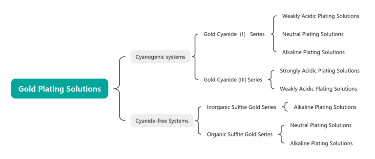
1. Types and Characteristics of Gold Plating Solutions
Table 1-1 Classification of Gold Plating Solutions
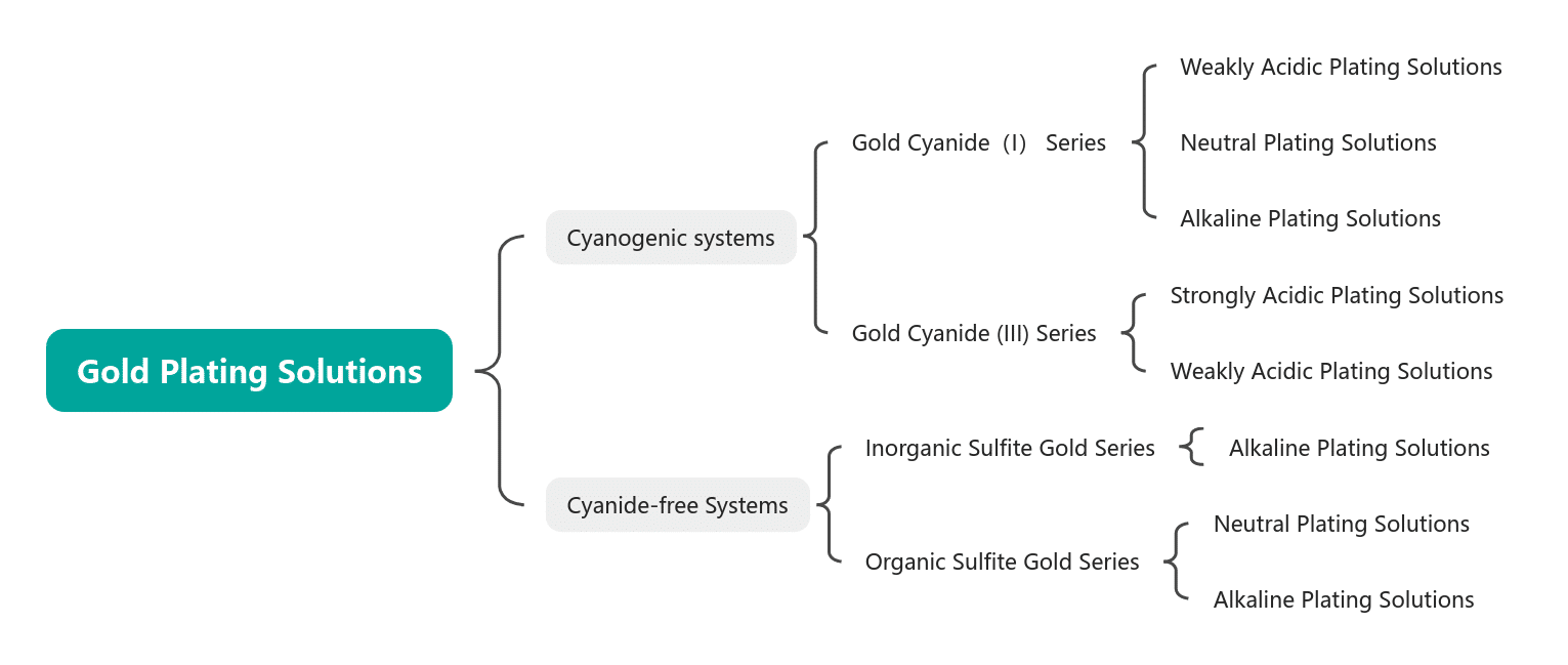
Table 1-2 Characteristics of Various Types of Gold Plating Solutions
| Electroplating solution | Gold Ligand | Acidity and Alkalinity | pH | Aspect | Appliance |
|---|---|---|---|---|---|
| Acid gold plating Hard gold plating | KAu(CN)2 | Weakly acidic | 3~5 | Gloss | Connectors, contacts, terminals, decorative parts |
| Neutral gold plating Soft gold plating Pure gold plaiting | KAu(CN)2 | Neutral | 6~9 | No gloss | Circuit board, semiconductor |
| Cyanide gold plating | KAu(CN)2 | Alkaline | 10~13 | Gloss | Decorative parts |
| Cyanide-free gold plating | Na3Au(SO3)2 | Neutral | 6〜8 | No gloss | Gold circuit patterns, circuit boards |
| Alkaline | 8~12 | Gloss |
2. Compounds of Gold used for Gilding
Gold has many valence states, among which the +3 valence compounds are the most stable, followed by +2 valence compounds, while +5 valence compounds decompose easily. Gold(I) in aqueous solution has several stable ligands, such as typical dihalogenoaurate(I) acid coordination salts, dicyanoaurate coordination salts, thiosulfate gold(I) acid salts, etc., among which cyanides are very stable, with a stability constant K=4×1028. Therefore, gold(I) and gold(III) compounds are used the most and are the most common, while gold(II) and gold(V) compounds are also increasingly understood and applied.
So far, potassium gold(I) cyanide is the most widely used and common main salt for gilding. Potassium gold(III) cyanide and sodium gold(I) sulfite plating solutions have been used more frequently in recent years.
1.1 Potassium Gold(I) Cyanide, KAu(CN)2 (hereinafter referred to as potassium gold cyanide)
(1) Relative molecular mass: 288.10. Preparation methods include chemical methods and electrolysis methods.
(2) Properties: The potassium gold cyanide prepared by this method is colorless crystalline, easily soluble in water, slightly soluble in ethanol, and insoluble in acetone and hexadecanol. It decomposes easily when heated in acidic conditions, is stable to light in the air, and its stability is significantly higher than that of similar copper and silver cyanide ligands.
(3) Preparation Methods
① Chemical Method
a. Dissolving gold: Place pure gold into diluted aqua regia (water volume ratio to aqua regia is 1:4) and heat to dissolve→After the gold block is completely dissolved, appropriately lower the temperature→Repeatedly add hydrochloric acid dropwise until no brown nitrogen dioxide is produced→Slowly concentrate until the solution turns deep reddish-brown, with tiny rolling shiny reduced gold powder appearing.
b. Neutralization reaction: Cool the solution to about 25℃. Under stirring→add saturated sodium hydroxide solution dropwise →until it forms a brownish-red semi-solid→Add potassium cyanide until the solution becomes colorless and transparent (with a small amount of aggregated gold powder particles precipitating).
c. Acidification (preparation of gold cyanide): Cool the solution to about 25℃→Under stirring, add hydrochloric acid dropwise→ until a bright yellow-gold cyanide precipitate forms→Stir and age at low temperature→Allow it to stand for layering, naturally cool it to room temperature, remove the upper waste liquid, filter it, and wash the yellow precipitate with warm water.
d. Synthesis of potassium gold cyanide: Place gold cyanide into a small amount of water→ Under stirring, add a measured amount of saturated potassium cyanide solution→until the solution becomes colorless and transparent→Filter to remove gold powder→Concentrate→Cool to crystallize→Remove the mother liquor→Dry the white crystalline potassium gold cyanide at 80℃→Seal and package.
Using this method to prepare potassium gold cyanide, the production equipment is simple and can effectively separate trace impurities in gold to prepare higher-purity potassium gold cyanide.
② Membrane Electrolysis: Method The Soviet Union was the first to use microporous ceramic diaphragm electrolysis to produce various metals and metal compounds. Domestic and foreign companies generally use organic membrane electrolysis to produce potassium gold cyanide. However, this electrolysis method has the problem of organic membranes being corroded by alkaline electrolytes, and the corrosion products pose significant harm to high-quality ICs, high-density circuit boards, and gold plating layers on contacts (Suzhou University Special Chemical Reagent Industrial Company has successfully developed a practical application).
1.2 Potassium Thiocyanate (III), K[Au(CN4)]·H2O
(1) Relative molecular mass: 358.15.
(2) Properties: Colorless crystals, easily soluble in water, when heated above 200℃, become an anhydrous salt, melt at a red heat, and decompose at higher temperatures.
(3) Preparation methods:
① Heat potassium gold cyanide in potassium cyanide solution;
② Dissolve gold trichloride in K3[Fe(CN)6];
③ Dissolve gold(III) dicyanide in K3[Fe(CN)6];
④ Treat potassium gold cyanide with bromine, and the resulting K[Au(CN)2Br2] reacts with potassium cyanide in methanol to prepare the product.
1.3 Gold Chloride
(1) Gold(I) chloride, AuCl
① Relative molecular mass: 232.46.
② Properties: pale yellow non-hygroscopic crystals begin to slowly decompose when heated above 150℃. Decomposes in water and ethanol and dissolves in chloralkali solution to form gold dichlorate.
③ Preparation method: Gold chlorate (HAuCl4, III) is placed under a high vacuum and heated to 156℃ to decompose and obtain the product.
(2) Gold chloride (III), HAuCl4
① Relative molecular mass: 303.37.
② Properties: Red needle-like crystals, melting point of 229℃, boiling point of 254 (decomposition), hygroscopic, aqueous solution is reddish-brown, forms H2[AuCl3O] in acidic solution. Slowly decomposes in a neutral aqueous solution, precipitating gold. Evaporation of the aqueous solution yields orange crystalline dihydrate salt, soluble in ethanol and ether.
③ Preparation method: At temperature between 225~250℃, the chlorine gas is passed through 120〜127kPa (900-950mmHg) gold powder to be prepared. Alternatively, dissolve gold in aqua regia, repeatedly add hydrochloric acid to remove nitric acid, then slowly heat at low temperature to remove excess hydrochloric acid, concentrate, cool, and crystallize to obtain the product.
1.4 Gold(III) Oxide, Au2O3
(1) Relative molecular mass: 441.93.
(2) Properties: Black (brown) powder or crystalline polymer structure, a gold compound surrounded by oxygen atoms forming a planar tetracoordinate complex. It decomposes slowly in sunlight, begins to release oxygen when heated to 110℃, becomes gold(I) oxide at 160℃, and loses all oxygen at 250℃, becoming an amphoteric oxide insoluble in water but soluble in hydrochloric acid and alkaline aqueous solutions.
(3) Preparation method: Dissolve gold in aqua regia, repeatedly add hydrochloric acid and heat (5 times) to remove nitric acid, add sodium carbonate until alkaline to produce a precipitate, wash with water, centrifuge, perform electrodialysis for 2 weeks, then dry at 140~150℃ to obtain the product.
Section II Thin Gold Plating
Electroplating thin gold solution, or brush plating gold solution, differs from flash plating (strike plating) gold solution. Brush-plating gold solution is usually based on alkaline cyanide liquids, with many types ranging from pure gold to alloys, such as potassium gold cyanide plating solutions with various ligand systems. Some companies also use their own specially developed plating solutions. Flash-plating gold solutions are mostly acidic and can serve as the base plating layer for thick gold layers, using higher current densities in a short time to plate a thin gold layer to improve the dispersion and adhesion of the upper thick gold plating layer.
Table 1-3 shows the composition and operating conditions of some representative brush plating thin gold plating solutions. Among them, phosphate acts as a buffer and also serves as a conductivity agent. From the newly prepared plating solution can achieve a good coating, but impurities quickly form in the plating solution after electrification, causing the plating layer to easily develop color differences. The main reason is that when the temperature of the plating solution rises, cyanide undergoes a decomposition reaction. Therefore, the plating solution must be treated after a period of use, commonly by filtering with activated carbon.
Table 1-3 Various Representative Brush Plating Thin Gold Plating Solutions
| Componente | Pure gold plating solution | Hamilton color | White 1 | White 2 | Greenish gold | Red gold | ||
|---|---|---|---|---|---|---|---|---|
| Galben | Roz | Verde | ||||||
| KAu (CN)2/(g/L) | 1.23 ~ 2.0 | 1.23 ~ 2.0 | 1.23 ~ 2.0 | 1.23 ~ 2.0 | 0.41 | 0.33 | 2 | 0.82 |
| Free KCN/(g/L) | 7.5 | 7.5 | 2.0 | 2.0 | 15 | 15 | 7.5 | 4 |
| K2HPO4/(g/L) | 15 | 15 | 15 | 15 | 15 | 15 | 15 | 15 |
| K2Ni(CN)4/(g/L) | - | 0.26 | 0.26 | 0.26 | 1.1 | - | - | 0.21 |
| K2Cu(CN)3/(g/L) | - | 0.13 | 1.1 | - | - | - | - | 2.64 |
| K2Ag(CN)2/(g/L) | - | - | - | 0.05 | - | - | 0.26 | - |
| K2Sn(OH)6/(g/L) | - | - | - | - | - | 2.11 | - | - |
| Plating solution temperature /℃ | 60 ~ 70 | 60 ~ 70 | 60 ~ 70 | 60 ~ 70 | 65 ~ 70 | 65 ~ 70 | 55 ~ 70 | 55 ~ 70 |
| Densitatea curentului/(A/dm2) | 1 ~ 4 | 1 ~ 3.5 | 2 ~ 5 | 1 ~ 4 | 3 ~ 6 | 3 ~ 5 | 1 ~ 3 | 3 ~ 4 |
When electroplating pure gold, metals other than gold in the plating solution significantly impact the plating layer’s color. Copper makes the plating layer noticeably red, nickel and zinc make the plating layer white, and lead easily causes black, spotty, rough, gray-brown substances to adhere to the surface of the plating layer. Therefore, the color of gold alloy plating layers can be obtained by adding various metals. However, it isn’t easy to achieve the ideal color tone effect in actual electroplating processes.
The anode of the gold plating solution usually uses insoluble anode materials, such as stainless steel and black platinum-titanium mesh plates, and depending on the plating solution, carbon plates can also be used. After a certain current has consumed the plating solution, it should be analyzed regularly to replenish the concentration of gold ions, ligands, and other active components. An ampere-hour meter can be used for automatic calculation and addition to daily work. There is also a lot of electroplating solution take-out during the thin gold plating process, which must be pre-calculated before plating to replenish the consumption and loss in time. The process flow of thin gold plating is shown in Figure 1-1.

In the process flow, the concentration of the flash gold plating solution is about 1/5~1/3 of the concentration of the main plating solution (surface layer or upper gold layer). After the surface of the plated part is completely covered with an extremely thin gold layer, it is then placed into the main plating solution to plate the gold layer with the required color tone.
Residual cyanide on the surface of the gold plating layer can form water stains, affecting the appearance and electrical performance of the plating. Therefore, plated parts must be thoroughly cleaned and dried after gold plating. In addition to heating for drying, special products can use organic solvents for dehydration treatment. For example, dehydration and drying with anhydrous ethanol will not affect the gold plating layer color, and the drying speed is also fast.
The brush gold plating layer is very thin and generally controlled below 0.1μm. Various organic protective films are mostly applied on the thin gold layer when used as a surface plating layer to prevent easy wear and discoloration. The most commonly used organic protection is the acrylic melamine series resin, with a film hardness approximately equivalent to the hardness of a 3H~4H pencil and thickness of 10~15μm. Electrophoretic coating often uses anionic acrylic melamine resin.
Because the thin gold plating layer surface quickly deposits a uniform and consistent color in a short time, the plating process generally adopts cathode movement or jet stirring of the plating solution. By controlling the temperature of the plating solution, the concentration of gold ions, and the current density, conditions are regulated to suppress color differences in the plating layer.
Section III Thick Gold Plating
Table 1-4 Composition and Operating Conditions of the Plating Solution and Properties of the Plating Layer
| Gold compound | Types of Electroplating | Conductive Salts | Alloy Metal pH | Compoziție | Precipitate structure | Caracteristici |
|---|---|---|---|---|---|---|
| Potassium gold chloride | Weak acidity | Citric acid, oregano phosphoric acid, amino sulfonic acid, tartaric acid, oxalic acid | Pure gold, cobalt, nickel, iron, indium, tin 3.0~5.0 | Citric acid + sodium citrate 80~100g/L Potassium gold cyanide 8g/L Nickel sulfamate 3.0g/L Zinc acetate 0.5g/L | Layered structure, with organic polymer eutectic between layers | It can obtain bright and hard precipitates; the plating solution is easy to adjust, and low-temperature plating is possible. |
| Neutral | Phosphoric acid, sulfuric acid, boric acid, organic acids | Pure gold, precipitate, crystal modifier: titanium, selenium 5.0 ~ 8.0 | Potassium gold cyanide 2 ~16g/L Potassium citrate 120 ~150g/L Potassium phosphate 10~50g/L Ammonium sulfate 20~150g/L One of Ti, Ce, Te, Bi 0.01~40mg | Columnar or needle-like crystals, impurity co-precipitation less | Pure gold plating layer 99.99%; precipitated practical soft, semi-bright or dull thick plating layer; accumulation of impurities affects the lifespan of the plating solution. | |
| Alkaline | Cyanide, carbonate, pyrophoric acid | Pure gold, silver, cadmium, zinc, antimony 8. 5 〜 13. 0 | Pure gold, silver, cadmium, zinc, antimony 8. 5 〜 13. 0 | Grain boundaries with precipitation of cyanide polymers | Very uniform thick gold layer of about 300μm can be obtained; pure gold to 9K alloy plating layer can be obtained; insensitive to impurities, easy management of plating solution |
(1) The role of polyethyleneimine – high molecular weight polyamine organic compounds: Organic compounds are selectively adsorbed within the Helmholtz double electric layer, enhancing the polarization effect. During the electrodeposition process, organic substances continuously adsorb on active growth points, inhibiting the deposition and movement of gold across the cathode surface, resulting in a smooth and bright finish. However, a certain amount of organic matter co-deposited into the lattice of the deposited crystals seriously adversely affects the physical properties of the plating layer, especially its wear resistance. Generally, this is improved by adding other metals to produce co-deposition to improve the adverse effects of organic substances.
(2) The role of other semi-metals such as arsenic, thallium, selenium, and lead: Adding semi-metals not only produces a good bright gold plating layer from cyanide gold plating solution but also achieves a very bright gold plating layer from sulfite plating solution. Generally, an additional amount below 10-6 can produce a very obvious characteristic effect.
The brightening principle of semi-metals: semi-metal substances uniformly adsorb on the cathode surface, catalyze, promote the nucleation of gold crystals, generate more growth points, and promote uniform crystallization and deposition.
(3) The role of eutectic of transition metals cobalt, nickel, iron, etc.: The bright gold plating layer alloyed with cobalt and nickel contains a certain amount of carbon. If the carbon content is below 0.1%, a bright gold plating layer cannot be obtained even if cobalt undergoes eutectic.
Isotope 14C experiments have proven that the carbon originates from the cobalt-cyanide complex ligand. Dissolving the gold plating layer containing cobalt and nickel acidic plating solution with aqua regia can separate substances containing carbon. Under the microscope, the appearance of the aqua regia-treated material resembles plastic. This membrane-like polymer forms a large contact resistance on the surface of the plating layer.

1. Alkaline Gold Plating
Among all gold plating solutions, the alkaline cyanide gold plating solution is the oldest electrolytic gold plating solution. Alkaline cyanide gold plating solution is widely used for plating pure gold, gold alloys, and decorative gold plating and can also be used for functional electronic gold plating. The plating solution generally consists of potassium gold cyanide, free cyanide, potassium carbonate, etc. Various metal salts can be added according to different needs when plating gold alloys.
Gold plating with an alkaline cyanide gold plating solution results in good coating uniformity and wettability, and it is very suitable for plating gold alloy coatings with low gold content. It can plate gold layers from low K values to high K values. The plating solution has a high free cyanide content, making it less susceptible to impurities. Free cyanide can dissolve gold, so the plated items must be cleaned immediately after removal from the plating bath; otherwise, residual plating solution on the surface will cause defects such as a wavy appearance.
Cyanide-free gold plating layers are mainly used for wafers, driver ICs for liquid crystal displays, gold bump welding pads for packaging, and circuit lines, terminals, and other substrate contact points. On wiring wafers with photosensitive resist films, the corner height of the gold bump welding pads is several tens of micrometers, and the thickness is 15~20μm. The produced CN- in cyanide gold plating solution can corrode the photosensitive resist film and the protective film around the substrate; therefore, cyanide-free and weakly acidic plating solutions are mostly used.
Alkaline gold plating solutions are mainly cyanide gold plating solutions, with added metals ranging from binary to quaternary; practical gold alloy plating layers are binary or ternary gold alloys. Representative compositions and operating conditions of alkaline gold alloy plating solutions are shown in Table 1-5.
Table 1-5 Composition and Operating Conditions of Alkaline Gold Alloy Plating Solution
| Types of Alloys | Compoziție și condiții de funcționare | |
|---|---|---|
| Binary Alloys | Gold-Copper alloy |
Potassium gold cyanide 12g/L Potassium copper cyanide 7g/L Potassium thiocyanide 10g/L 2-Pyridine carboxylic acid 8g/L pH 8(adjusted with KOH) 70℃, 0.4A/dm2 |
| Gold-Silver Alloy |
Potassium gold cyanide 15g/L Potassium silver cyanide 3g/L Potassium nickel cyanide 20g/L Potassium cobalt cyanide 10g/L Potassium cyanide 80g/L Ammonium hydroxide 20g/L 15℃,0.6A/dm2 |
|
| Gold-Tin Alloy |
Potassium gold cyanide 30g/L Stannous nitrate 7g/L Potassium pyrophosphate 100g/L Room temperature,1A/dm2 |
|
| Ternary Alloys | Gold-copper-cadmium alloy |
Potassium gold cyanide 15g/L Potassium copper cyanide 200g/L Potassium Cadmium Cyanide 5g/L L-Glutamic acid 50g/L 70℃,1A/dm2 pH 8(adjusted with KOH) Au:Cu:Cd=70:15:15 |
1.1 Gold-silver alloy plating
Table 1-6 Composition of Gold-Silver Alloy Plating Solution
| Compoziție și condiții de funcționare | Parametrii | Compoziție și condiții de funcționare | Parametrii |
|---|---|---|---|
| Potassium Gold Chloride (calculated as Au)/(g/L) | 8 | Surfactant | Cantitate mică |
| Potassium silver chloride (calculated as Ag)/(g/L) | 2.5 | Temperatură / ℃ | 27 |
| Free potassium thiocyanate/(g/L) | 100 | Current density /(A/dm2) | 1 |
| Amine salt/(g/L) | 5 |
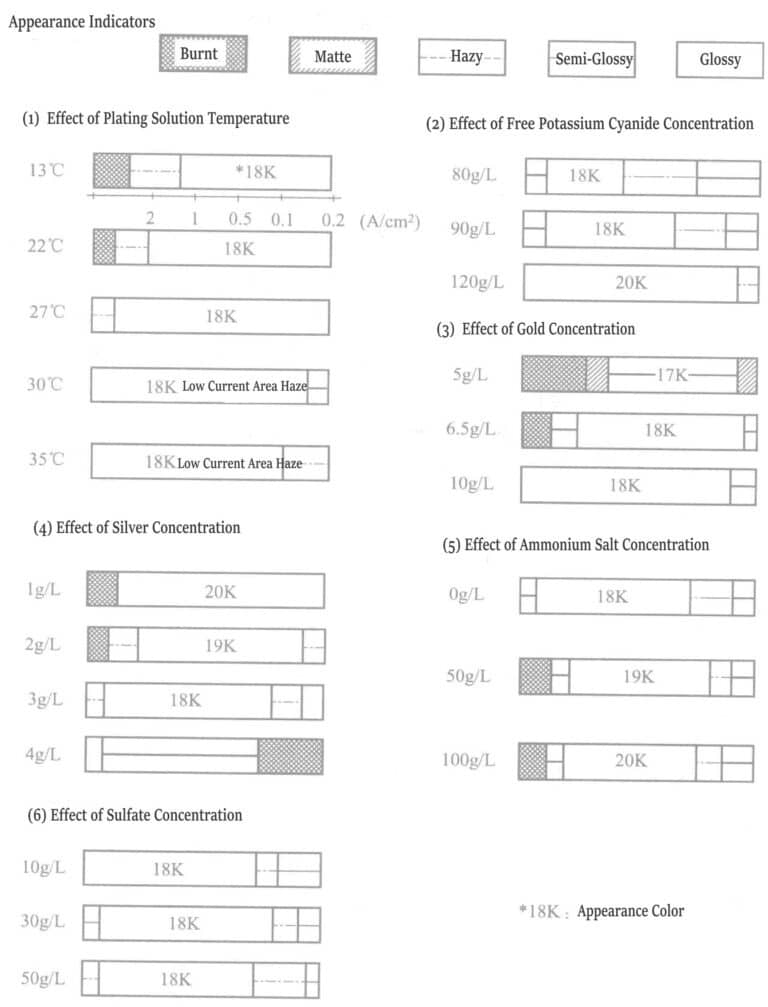
The concentration of free potassium cyanide should not be less than 90g/L, generally, above 100g/L, which is more appropriate. Exceeding 120g/L increases polarization suppresses silver deposition, increases gold deposition rate, and forms a high-grade gold layer.
The gold content is adjusted according to the K value of the gold alloy by regulating the concentrations of gold. And silver in the plating solution. For example, when the silver concentration is 2.5g/L in the alloy plating layer, the gold concentration must be controlled within the range of 7~10g/L, to obtain an 18K gold.
Influence of silver concentration: when the silver concentration is low, the brightness range of the plating layer is wide, and the gold content is high.
Influence of amine concentration: When the amount of amine is added to 30g/L, the gold deposition rate does not change, but compared to no addition, it increases the brightness of the plating layer. When the amount of amine added increases to 50g/L, the gold deposition rate increases, causing a “burning” phenomenon at high current density areas. The main purpose of adding amine is to reduce the stress of thick gold plating layers. Adding ligands such as triethylenetetramine (10~30g/L) to bright gold-silver alloy plating solutions can produce better results.
Figure 1-4 shows the relationship between the temperature of the plating solution, current density, and the gold deposition rate. The hardness of the deposited gold layer is Hv25170~210. The surface and cross-sectional conditions of the gold plating layer: after directly plating gold with a thickness of 4μm on the nickel plating layer, the peeled gold layer was observed under an electron scanning microscope. The results are shown in Figures 1-5 and 1-6, indicating that the surface and cross-section of the plating layer have no pores and are dense. The crystallinity of the gold plating layer was tested by X-ray diffraction after directly plating about 10μm of gold on a copper plate. The peak of the base copper layer was not detected; only the peaks of the gold-silver alloy plating layer were measured, and the crystallization grew in the (111) plane.
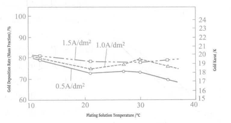
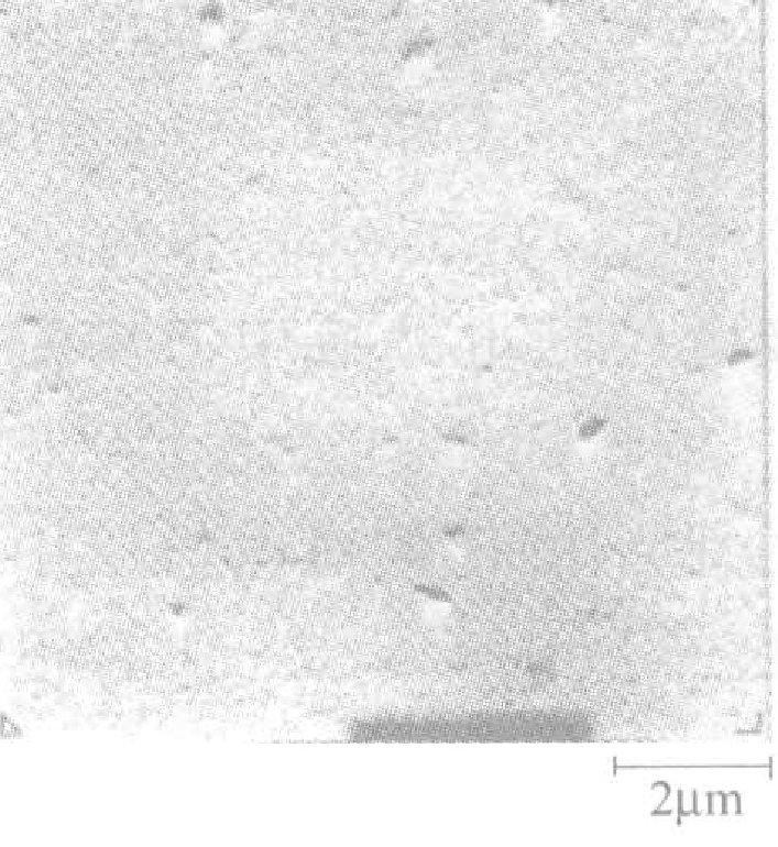
Figure 1-5 Surface state of gold-silver alloy plating
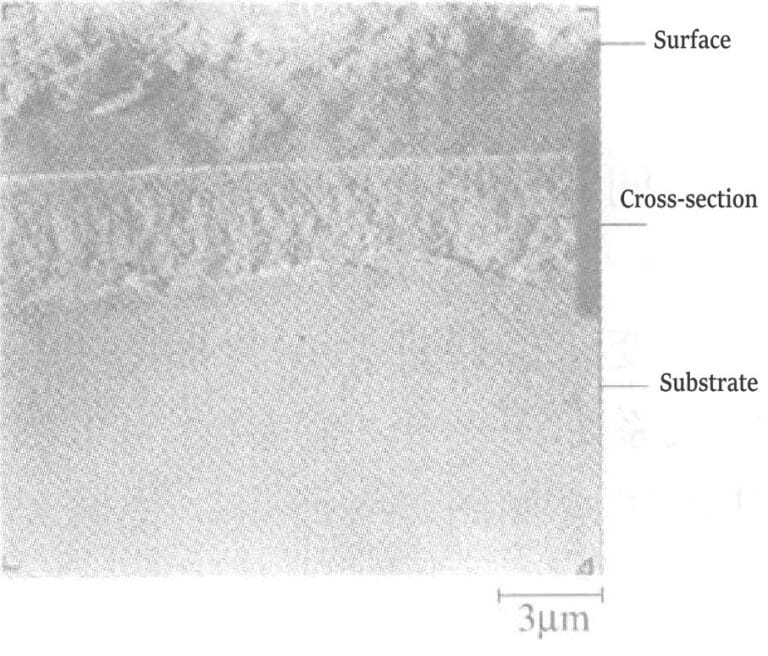
Figure 1-6 Organizational structure of gold-silver alloy coatings
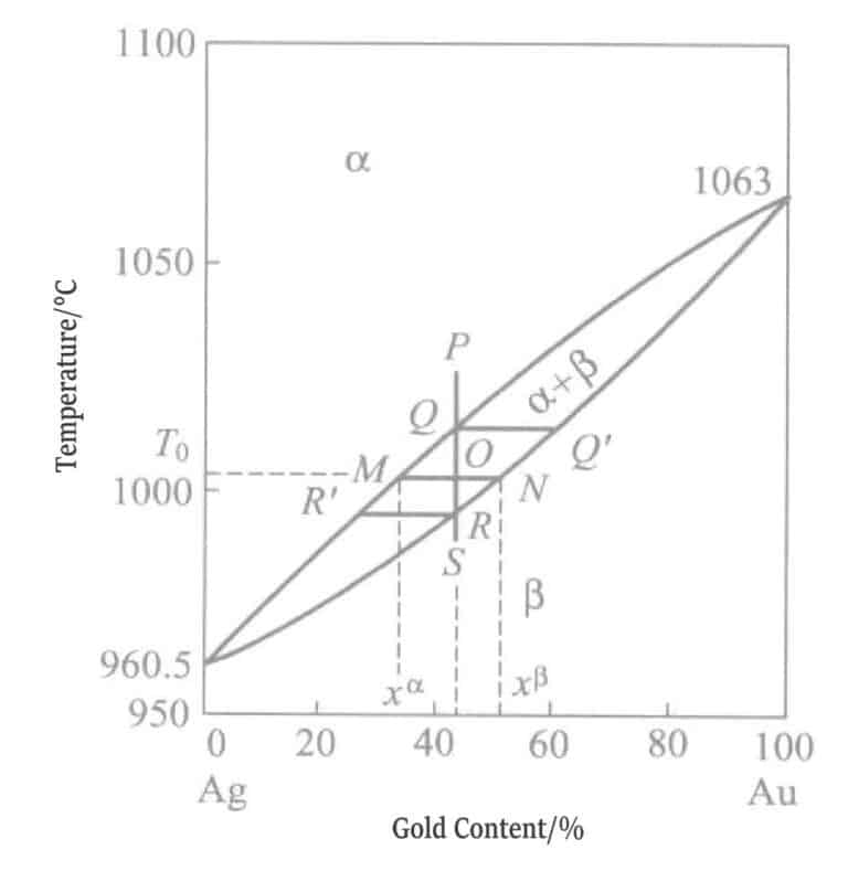
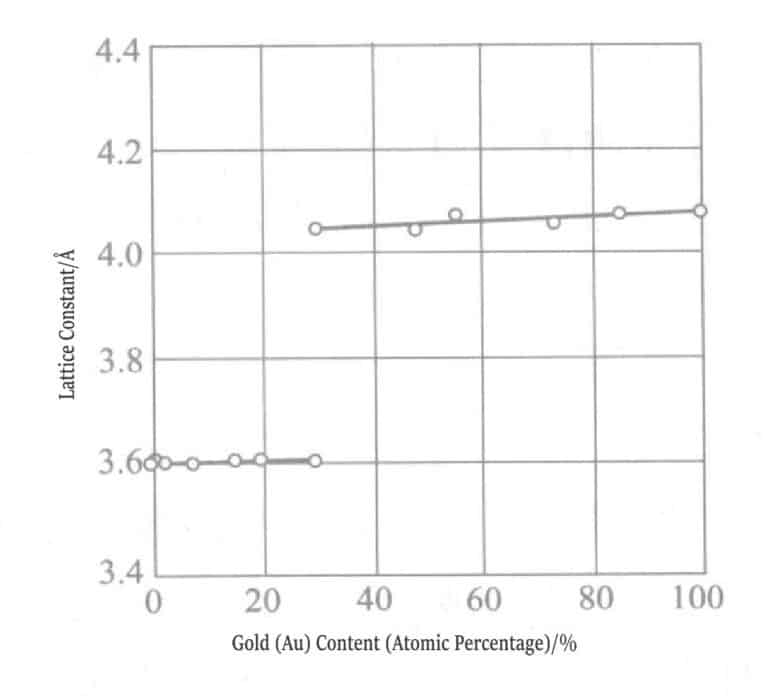
The state of the gold-silver series alloys is shown in Figure 1-7, belonging to a full-ratio solid solution, and both gold and silver have an fcc (face-centered cubic) structure, with atomic radii both being 1.44Å (1Å= 10-10m). Therefore, the lattice does not undergo distortion.
E. Raub also conducted X-ray diffraction studies on gold plating layers, confirming that the gold-silver series alloys form only one type of solid solution and possess excellent corrosion resistance.
E. A. Parker reported that this series of gold-silver alloys has excellent corrosion resistance and conductivity, is highly valuable for manufacturing communication equipment parts, and its unique gold-green tone and corrosion resistance make it suitable as a base plating layer for thick gold plating.
1.2 Gold-plated Copper Alloy
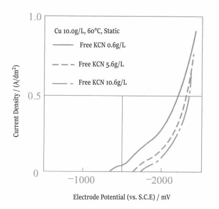
Figure 1-8 Polarization curve of copper plating solution
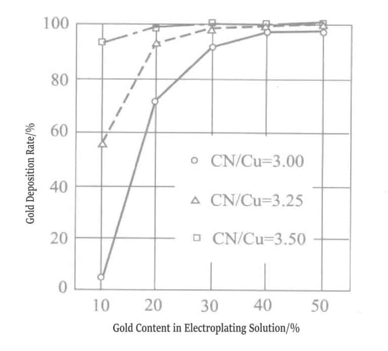
Figure 1-9 Variation of precipitated components in gold-silver alloy plating layer
Table 1-7 Composition and Operating Conditions of Alloy Plating Solution
| Compoziție și condiții de funcționare | Parametrii | Compoziție și condiții de funcționare | Parametrii |
|---|---|---|---|
| KAu(CN)2/(g/L) | 7.5 ~ 9.0 | Na2SeO4/(g/L) | 0.5 |
| K2Cu(CN)2/(g/L) | 130 | Electrolyte temperature/℃ | 60 |
| K2Cd(CN)4/(g/L) | 0.4 ~ 2 | Densitatea curentului/(A/dm2) | 0.75 |
| KCN/(g/L) | 15 |
Adding nickel salts to the gold-copper alloy plating solution increases the hardness of the plating layer. When the plating solution pH is close to acidic, the amount of nickel deposition increases. The cadmium-containing plating layer has a color similar to rose gold, displaying a very noble decorative tone.
The 18K cadmium-containing gold plating layer is a solid solution with high hardness, yield strength, tensile strength, and excellent corrosion resistance. Unfortunately, due to environmental protection issues, using metals such as cadmium is restricted by International Environmental Protection Organization conventions and must be strictly controlled within the allowable trace amounts. Cadmium is becoming increasingly regulated, generally only used in very special color adjustments, alloy plating, and electroforming 200~300μm hollow gold, where only used during 18K gold-copper-cadmium alloying plating.
2. Acidic Gold Plating
The acidic gold plating solution is stable within a pH range of about 3, capable of depositing nickel or cobalt that does not undergo electrolysis in alkaline gold plating solutions, forming gold-nickel or gold-cobalt alloy coatings. The coating’s fine crystals do not distort or dislocate and have no voids, allowing long-term stable growth.
The coating deposited from acidic plating solution has a bright appearance and is called a bright plating solution. The coating from an acidic plating solution has high hardness and is also known as a hard gold plating solution (Table 1-8). Various metals added to organic acid plating solutions are called metal brighteners.
Table 1-8 Main Components and Variations of Acidic Gold Plating Solution
| Compoziție și condiții de funcționare | Reference parameters | Plating Solution Condition |
|---|---|---|
| KAu(CN)2 (g/L) | 4 ~ 6 (calculated as Au) | High concentration (about 16g/L), suitable for high-speed gold plating |
| Citric Acid Hydrate (g/L) | 50 〜 100 | Add citric acid as a ligand for the drill and as a buffer for the plating solution, or add other cobalt ligands |
| CoSO4 • 7H2O/(g/L) | 0. 1 〜 3. 0(calculated as Co) | Generally, add cobalt and plating Add sulfuric (calculated as Co) acid when alloying Au-Ni |
| pH | 3. 5 〜 4. 5 | Current efficiency is high when pH is high, but mist is easily generated |
| Temperatură/℃ | 30 〜 40 | High liquid temperature easily generates mist |
Table 1-9 Properties of Acidic Gold Plating Solution
| Effect of pH value | Plating solution properties | Application | |
|---|---|---|---|
| pH 3 | pH 3 ~ 5 | ||
|
① Gold– cobalt, gold– nickel alloys ② Cobalt and nickel are highly active and precipitate more; hydrogen evolution overpotential is low, current efficiency increases, plating efficiency is low |
① Eutectic bright, hard alloy; hydrogen evolution overpotential is high, current efficiency is low, plating efficiency is high ② No free cyanide present in the plating solution ③ During the precipitation of gold from KAu(CN)2, part of CN- forms HCN, which diffuses into the air, affecting the environment |
① No free cyanide present,During the precipitation of gold from KAu(CN)2, CN- forming HCN ②With the increase of electroplating time, due to accumulation of K+, increase in plating solution pH ③ The plating solution is acidic; On the Pt/Ti anode, the hydrogen evolution overpotential is high, and organic carboxylic acids such as citric acid undergo Kolbe reaction to form viscous polymers, so a large-area anode plate is required to suppress this reaction |
① Decorative electroplating ② In addition to removing cobalt and nickel, indium, zinc, and iron can also be added for color adjustment |
When no free cyanide is present in the plating solution, potassium gold cyanide deposits gold, and cyanide complex ions (CN – ) form HCN, which enters the atmosphere and diffuses.
In the electroplating tank, gold plates are rarely used as anodes; generally, stainless steel plates or Pt/Ti plates are used. In acidic plating solutions, the oxygen evolution overpotential at the anode is high, and carboxylic acids such as citric acid tend to undergo Kolbe reactions at the anode. Methods such as increasing the anode area can prevent the formation of sticky polymeric deposits.
The co-deposition of nickel and cobalt increases the hardness of the cyanide hard gold plating layer. After reflow soldering at 260℃, the contact resistance increases sharply. Adding aliphatic compounds such as ethanol to the plating solution can inhibit changes in contact resistance after reflow soldering and significantly increase the current density range of the plating solution. For example, when plating gold on flexible printed circuit boards (copper), adding mercapto compounds can inhibit copper tube dissolution and stably plate thick gold for a long time.2.1 Gold-Cobalt Alloy Plating
Acidic gold plating generally uses organic acid gold plating solutions from the citric acid and citrate series. The ligand potassium gold cyanide in the aqueous organic acid solution dissociates to produce free cyanide, making the solution an electroplating bath with a pH of about 3. Various components, such as ligands other than citric acid, are added as needed, including EDTA. The pH adjuster used is sodium bisulfate. Conductive salts include potassium hydrogen phosphate, dihydrogen phosphate, ammonium hydrogen phosphate, sodium pyrophosphate, etc. Buffers used include potassium sulfate, sodium sulfate, etc. Electroplating conditions: gold concentration of 1~8g/L, current density of 0.3~10A/dm2, plating solution temperature of 25~40℃. Generally, no adverse phenomena, such as fogging, occur when plating a thick gold layer. The brightener in the plating solution only needs to add a small amount of transition metals or metalloids. Cobalt and nickel are representative metallic brighteners.
R. Duva et al. proposed the gold plating solution in Table 1-10 in a patent and successfully applied for many other patents for acidic gold plating.
Table 1-10 Composition of Representative Acidic Gold Plating Solutions
| Compoziție și condiții de funcționare | 1 | 2 |
|---|---|---|
| Citric Acid + Sodium Citrate /(g/L) | 80 | 80 |
| Gold (Potassium Gold Cyanide) /(g/L) | 8 | 8 |
| Nickel (Nickel Sulfate) /(g/L) | 3 | |
| Zinc (Zinc Acetate) /(g/L) | 0.5 | |
| Indium (Sulfate) /(g/L) | 5 | |
| Cobalt (Sulfate) /(g/L) | 3 | |
| pH | 4〜5 | 3〜4 |
| Temperatură / ℃ | 21 | 21 |
| Current density /(A/dm1) | 1 | 1 |
| K① value | 23 | 21 |
① National Standard GB 11887-89 stipulates that the gold content of 1K is 4.166% (“K” is the abbreviation of the English word carat and the German word karat).
21K = 21×4. 166% = 87. 486% (875‰)
24K gold is often mistakenly referred to as pure gold or labeled as “1000‰” with an actual gold content of 99,99%, equivalent to 23.988K (international organizations have prohibited labeling as “pure gold,” “9999 gold,” and “24K gold”).
There are many views on the role of cobalt in plating solutions. Eisenmann analyzed the content of potassium, cobalt, carbon, nitrogen, and other elements in the gold plating layer and found that the ratio of these elements corresponds to the ratio of KCo[Au(CN)2]3 molecules. Therefore, it was concluded that it acts as a brightener in the plating solution, rather than cobalt alone providing the brightening effect. In the plating solution, it forms within the Helmholtz double layer and undergoes only minimal dissolution under typical plating conditions. After ligand formation, it exhibits electrochemical behavior similar to organic brighteners and is adsorbed cathodically. This transition metal shows brightening effects over a wide pH range, consistent with cobalt and other transition metals only exhibiting brightening effects in acidic plating solutions.
Theoretically, the ratio of potassium, cobalt, carbon, and nitrogen in the plating layer must be 1:1:6:6, but these ratios vary greatly. The potassium-to-cobalt ratio ranges from (1.0:0.4)~(1.0:5.5) depending on the condition of the plating solution and operating parameters; the cobalt-to-carbon ratio varies between (1:3)~(1:10), while the carbon-to-potassium ratio remains basically stable at 3:1.
The above results do not negate the fact that KCo[Au(CN)2]3 is the main brightener in the gold plating solution and reports of cobalt, CoOOH, or cobalt cyanide have also been detected simultaneously in the gold plating solution. The formation of KCo[Au(CN)2]3 can also be explained by many characteristics of the acidic gold plating solution, such as considering this compound merely as a simple intermediate in the electroplating process, with other reactions representing the brightening process. In summary, it is believed that factors such as the reduction of potassium and cobalt, cyanide ligand salts, and the formation of polymers contribute to the brightening of the gold plating layer.
The composition of representative bright, low-stress, wear-resistant gold plating solutions is shown in the table1-11. The theoretical assumptions are quite consistent with the gold plating solution in the strong coordination force of cobalt’s coordination group from the ligand of KCo[Au(CN)2]3 ligand dissociation of cobalt ions, prompting the generation of KCo[Au(CN)2]3, the generation of the occurrence of the role of the brightening. When added in the form of cobalt salt of EDTA, the total cobalt amount of KCo[Au(CN)2]3 was 6 g/L.
Table 1-11 Composition of Representative Bright, Low-Stress, Wear-Resistant Gold Plating Solutions
| Element | Mass ratio/% | Atomic ratio /% | Element | Mass ratio/% | Atomic ratio /% |
|---|---|---|---|---|---|
| K | 0. 26 | 1.3 | Co | 0.24 | 0.80 |
| C | 0.24 | 3.94 | Total | 1.00 | 9.70 |
| N | 0.26 | 3.66 |
All gold-plating electrolytes contain strongly coordinating cyanide ligands (except for the gold sulfite salt system). The cyanocobalt ion [Co(CN)6–] is one of the most stable coordination salt complexes known among ligands, and the cyanide salt coordinated with Co(III) is almost non-toxic.
If free cyanide exists in the acidic gold plating solution, HCN will be produced, so the free cyanide concentration must be very low. However, if the pH increases, the concentration of free cyanide in the plating solution increases. When analyzing cobalt in the plating solution, it is necessary to distinguish between “inactive cobalt” and “active cobalt,” the former being Co(III) and the latter Co(II).
When changing the operating conditions of the plating solution, the following aspects should be noted.
(1) pH has many effects on the plating solution.
At high pH value of 5.0, the concentration of free cyanide increases, promoting the formation of cyano cobalt(III) coordination salt and increasing the solubility of KCo[Au(CN)2]3, thereby reducing the brightness of the plating layer. The supply of cobalt in the Helmholtz double electric layer (Figure 1-3) is affected by the coordination ability of the ligands, which depends on the pH of the plating solution. As the pH of the plating solution continuously rises, acidic plating solutions require continuous addition of buffer agents.
At low pH, hydrogen ions discharge preferentially, resulting in lower current efficiency of the plating solution.
(2) Plating solution temperature: As the temperature of the plating solution rises, the solubility of KCo[Au(CN)2]3 increases and the brightness of the plating layer decreases.
Temperature also affects coordination strength. When the plating solution temperature increases, raising the concentrations of gold and cobalt salts can effectively reduce this effect.
(3) High-speed plating: High-speed plating solutions require regular adjustments. To prevent local concentration reduction at the cathode (concentration polarization), the concentrations of gold and cobalt should be kept below the upper limit. For the same reason, stirring should be performed with high-concentration solutions, and jet flow stirring is used during high-current density plating. High temperatures can enhance the stirring effect. The main characteristic of high-speed plating is high current density at both the anode and cathode. Transition metal brighteners can achieve optimal performance under high current density at both electrodes. However, the following situations must be noted:
① The pH of the plating solution rises quickly.
② Co3+ is generated rapidly.
③ Cobalt(III) cyanide coordination salts are easily formed.
④ Organic ligands promote the oxidation of the plating solution.
Over the years, many plating solutions containing organic additives have been developed to increase the current density range of cobalt-gold and nickel-gold alloy plating solutions, achieving high-speed plating at lower concentrations.
(4) Current Efficiency: Current efficiency is the ratio (%) of the current consumed in the actual gold plating process to the total current used. Other reduction reactions consume the remaining current.
Using Co3+ + e– =Co2+, from the perspective of current consumption, it can be understood that the generation and adsorption of KCo[Au(CN)2]3 increased polarization effects, resulting in the promotion of hydrogen discharge.
Important conditions that help the generation of KCo[Au(CN)2]3, such as low pH value, high concentration of free Co2+, and low temperature of the plating solution, reduce current efficiency.
Using appropriate ligands can regulate the effective cobalt concentration and generation of KCo[Au(CN)2]3, resulting in a bright plating layer and optimal current efficiency.
(5) Adding metals, that is, metal brighteners, hinders the generation of KCo[Au(CN)2]3; for example, lead hinders the formation of brighteners by adsorption, thereby reducing current efficiency.
(6) Stirring: Compared with plating solutions of other metals, due to the inventory of gold raw materials, price, and other cost factors, and the fact that most of the current in the plating process is consumed by electron transfer in high-concentration conductive salts, plating solutions generally use the lowest possible concentration.
Au(CN)2– is not attracted to the cathode in electrophoresis and is supplied to the Helmholtz double layer (Figure 1-3) by diffusion; therefore, stirring is an important condition for supplying gold coordination salt and brighteners to the cathode.
Stirring can improve current efficiency, but at the same time, it will further increase current efficiency in high-current density areas, worsening the uniformity of the plating layer.
With the advancement of local plating technology, the problem of poor dispersion of the plating layer has gradually decreased. Currently, additives are commonly used to expand the current density range to improve plating uniformity.
Copywrite @ Sobling.Jewelry - Producător de bijuterii personalizate, fabrică de bijuterii OEM și ODM
2.2 Gold-Nickel Alloy Plating

Figure 1-11 Nickel content and lattice constant of gold-nickel alloy coating

Figure 1-12 Nickel content and lattice constant of gold-nickel alloy coating
The relationship between nickel content and lattice constant in alkaline and acidic plating solutions for gold-nickel alloy electroplated layers was measured. Nickel forms a solid solution with gold at a maximum content of 5%, and when exceeding 5%, nickel precipitates as a simple mixture.
Comparative tests were also conducted on gold-nickel alloy plating layers and gold-cobalt alloy plating layers, and the results showed that the properties of the two gold alloys differ significantly. Figures 1-13 and 1-14 show that the carbon, cobalt, and nickel content in gold alloys of the same composition change with the temperature of the plating solution. Cobalt decreases as the plating solution temperature rises, and the curves of carbon and cobalt are parallel, so the molar ratio of carbon to cobalt is approximately fixed at 4.
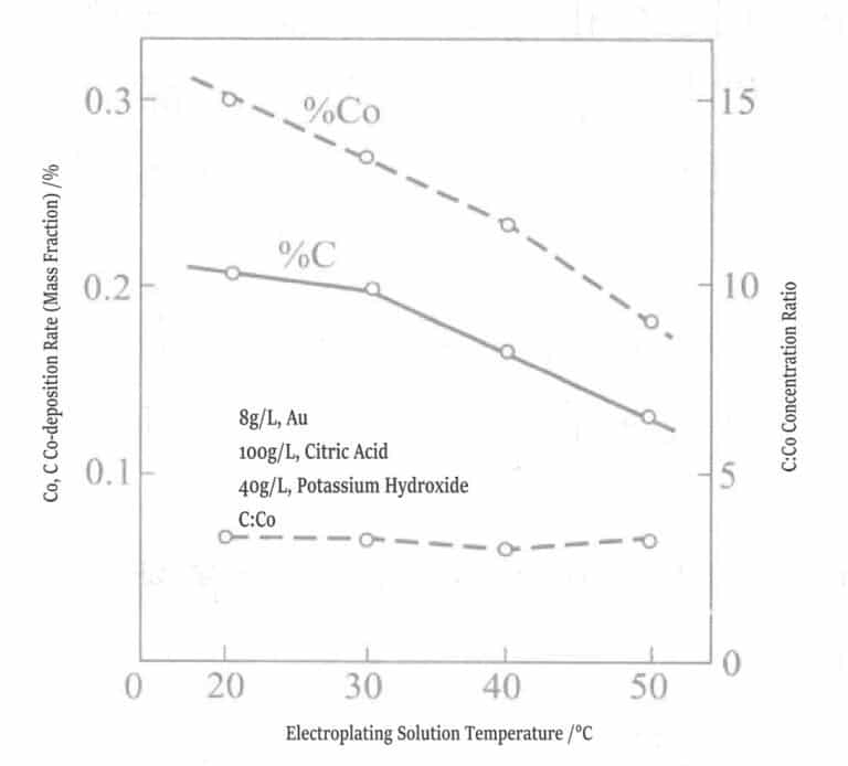
Figure 1-13 Relationship between plating solution temperature and cobalt, carbon co-deposition rate
(0.5g/L, pH 3.5, 1A/dm2 )
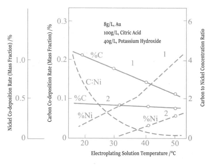
Figure 1-14 Relationship between plating solution temperature and co-deposition of nickel and carbon
1-0.5g/L, pH 3.5, 1A/dm2 ; 2-0.5g/L, Ni, pH 4.5, 1A/dm2
Figure 1-15 shows the effect of pH on nickel co-deposition. When pH is controlled above 4.5, the co-deposition of nickel in the plating layer is zero, while below pH 4.5, the plating layer is bright.
When other impurities are mixed into the gilding layer, the tensile stress of the plating layer increases. Figure 1-16 shows the relationship between the temperature of the gold-nickel alloy plating solution and the stress value within the plating layer.
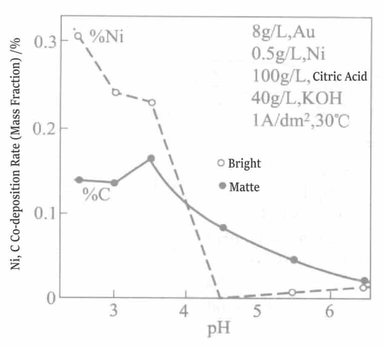
Figure 1-15 Effect of pH on nickel and carbon co-deposition rate
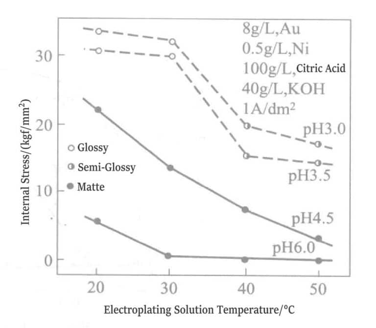
Figure 1-16 Relationship between internal stress value, pH, and plating solution temperature (1kgf/mm2 =980.665Pa)
As the thickness of these gold-plating layers increases, cracks are easily generated. The tensile strength of the gold-nickel alloy plating layer is shown in Figure 1-17. The tensile strength is greatly affected by thickness, and a good plating layer without cracks can only be plated to a thickness of 2~3μm.
When the pH is below 5, the plating solution can generate ligands. Currently, the binding force between citrate and nickel (Ni2+ ) is stronger than that of cyanide. Figures 1-18 shows the different conditions of the plating solution. If nickel is added in the form of K2Ni(CN)4, the carbon content in the plating layer increases sharply. The nickel content in the plating layer rises from a concentration higher than 0.3g/L in the plating solution. When the nickel concentration in the plating solution is below 0.3g/L, the plating layer is dull; above 0.3g/L, it becomes bright. However, if nickel is added as nickel sulfate to the plating solution, a bright effect can be produced even when the nickel concentration is below 0.3g/L. The reason is that nickel has already undergone co-deposition at a concentration level.

Figure 1-17 the relationship between gold plating thickness and tensile strength.
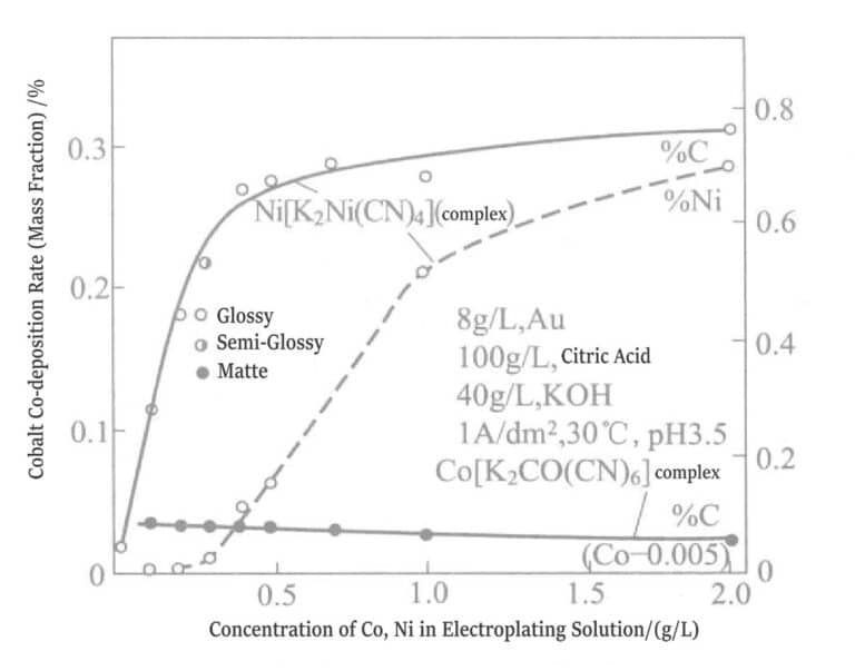
Figure 1-18 Effect of complex ions on the concentrations of cobalt and nickel in the plating solution and the co-deposition rates of cobalt, nickel, and carbon.
(1) Composition and operating conditions of the plating solution: The color of the plating layer is the key to decorative gold plating. In acidic organic acid plating solutions, the main components used are the following: gold salts, organic acids, nickel salts, brighteners, and stress relievers. Gold salts, such as potassium gold cyanide. Organic acids include citric acid, hydroxybutanedioic acid, and tartaric acid. Nickel salts include nickel salts of amidosulfonic acid, citric acid, sulfuric acid, gluconic acid, formic acid, boric acid, phosphoric acid, etc. Brighteners (metals) include indium, cobalt, zinc, cadmium, antimony, etc.
Stress relievers include magnesium, calcium, α-bipyridine, sodium alkylbenzene sulfonate, triethylenetetramine, hydrazine sulfate, amidosulfonic acid, etc.
(2) Factors affecting the color of gold-nickel alloy plating layers: Table 1-12 lists two types of plating solutions: plating layer colors, plating solution stability, physical properties, etc.
① Effect of nickel citrate: The concentration of nickel citrate calculated as nickel in the plating solution varies 15g/L, 20g/L, 25g/L, 30g/L, adjusting the color of the gold plating layer. When the concentration of nickel citrate is 15g/L, plating layer is bright golden yellow; when it is 20~30g/L, the color does not change. When 1g/L cobalt is added as cobalt sulfate, the color does not change, but the brightness of the plating layer does. After separately changing the plating solution’s temperature of 35℃, 40℃, 45℃, 55℃, the plating layer’s color still did not change.
Table 1-12 Composition and Operating Conditions of Two Gold-Nickel Plating Solutions
| Compoziție și condiții de funcționare | Nickel plating solution with citric acid | Nickel sulfamate plating solution |
|---|---|---|
| Citric acid /(g/L) | 150 | 150 |
| Potassium citrate /(g/L) | 100 | 100 |
| Nickel sulfamate (as Ni)/(g/L) | 15 | |
| Citric acid nickel (as Ni)/(g/L) | 25 | |
| Cobalt sulfate (as Co)/(g/L) | 1 | 0.5 |
| Potassium gold cyanide (as Au) /(g/L) | 2 | 2 |
| Potassium cyanide KCN/(g/L) | 1 | 1 |
| pH | 4.2 | 4.2 |
| Temperatură / ℃ | 40 | 40 |
② Effect of Nickel Aminosulfonate: In the plating solution, the concentration of nickel aminosulfonate is 5g/L, 10g/L, 15g/L, 20g/L, calculated as nickel; with the addition of 0.5g/L cobalt (cobalt sulfate), 2.5g/L gold (potassium gold cyanide) , the color of the plating layer changes significantly. When the nickel concentration is 5g/L, the plating layer is bright golden yellow; when it is 10g/L, it is light gold. Comparing the plating layers deposited using two nickel salts, the plating layer from the nickel citrate solution shows a bright golden yellow. In contrast, the plating layer from the nickel aminosulfonate solution is slightly blackish.
③ Effect of Nickel Sulfate: After a certain period, nickel sulfate plating solution produces nickel hydroxide precipitate and is unsuitable for use.
④ Current Efficiency: The relationship between current density and current efficiency for the two plating solutions is shown in Figure 1-19. When the current density is at 0.5A/dm2, 1.0A/dm2, 1.5A/dm2, there is no difference between the citrate nickel plating solution and the amino sulfonic acid nickel plating solution, and both the current efficiency is 22%~23%.
⑤ Gold Deposition Ratio: The gold content in the plating layer of the citrate nickel plating solution is higher than that in the plating layer of the amino sulfonic acid nickel plating solution by 1%~3% (mass fraction) (Figure 1-20).
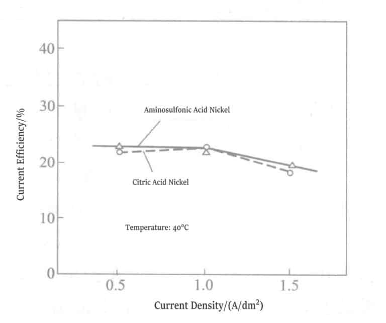
Figure 1-19 Relationship between Current Density and Current Efficiency
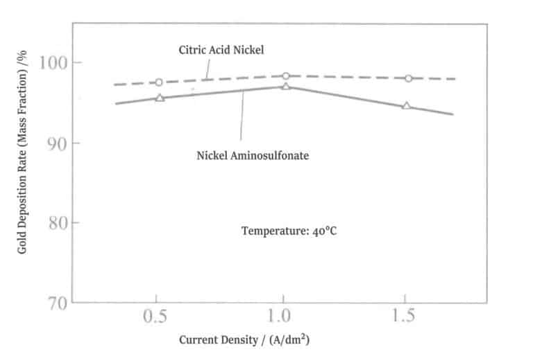
Figure 1-20 Relationship between nickel salt and gold deposition ratio
Table 1-13 Hardness of Cross-Sections of Two Types of Plating Layers
| Tip | Load/gf① | Duritate Hv |
|---|---|---|
| Nickel citrate plating solution | 25,50 | 280 ~ 310 |
| Nickel sulfamic acid plating solution | 25,50 | 210 ~ 240 |
| ① lgf=9. 80665× 10-3N。 | ||
The surface condition of two plating layers with thicknesses of 50μm is free of cracks, smooth, and semi-bright. When the nickel content (mass fraction) in the gold-nickel alloy plating layer is about 5%, the hardness is usually around Hv 200. Due to the large thickness of the plating layer, internal stress is generated, so the measured result exceeds Hv 200. The hardness of the plating layer from the amino sulfonate plating solution is low, which is influenced not only by the thickness of the plating layer but also by the stress-reducing effect of the amino sulfonate itself.
⑦ Effect of impurities: The experimental plating solution and operating conditions for the effect of impure metals on the appearance of the plating layer are shown in Table 1-14. Bright nickel was plated in a thin-film battery test tank to conduct thin-film battery plate tests. The results from the two plating solutions are shown in Figure 1-21, and the summary of results is shown in Table 1-15.
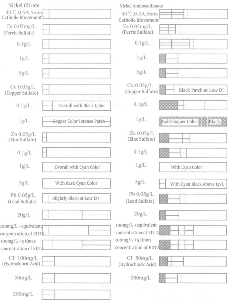
Table 1-14 Types and Addition Concentrations of Impure Metal Compounds
| Impure Compounds | Addition Amount |
|---|---|
| Fe in the form of ferrous sulfate | 0. 05g/L, 0. 1g/L, 1g/L, 5g/L |
| Cu in the form of copper sulfate | 0. 05g/L, 0. 1g/L, 1g/L |
| Zn in the form of zinc sulfate | 0. 05g/L, 0. 1g/L,1g/L, 5g/L |
| Pb in the form of lead sulfate | 100mg+times (molar ratio) EDTA 5mg/L, 20mg/L, 100mg+ Equivalent mole EDTA |
| Cl in the form of hydrochloric acid | 50mg/L, 200mg/L |
Table 1-15 Effects of impurities
| Impurități | Nickel citrate plating solution | Amino sulfonic acid nickel plating solution |
|---|---|---|
| Fe | No effect up to 5g/L | |
| Cu | At 0.1 g/L: Entire surface appears black; at 1 g/L: Distinct coppery precipitation becomes evident. | At 0.5 g/L: Blackening occurs in low current density areas; at 1 g/L: Surface becomes lusterless. |
| Zn | Up to 0.1 g/L: No observable effect; Above 0.1 g/L: Bluish golden yellow appears, with bluish tint intensifying proportionally with concentration increase. | |
| Pb | Around 5 mg/L: Slight blackening manifests in low current density areas. At approximately 20 mg/L: Hazy appearance emerges when EDTA-2Na is introduced. | Up to 20 mg/L: No significant impact observed. |
| Cl | At 200 mg/L: Marginal haze enhancement confined to high current density regions. | Around 200 mg/L: Essentially no detectable influence. |
Comparing the above results for the two types of plating solutions, the citric acid nickel plating solution is greatly affected by lead. In contrast, lead affects the amino sulfonic acid nickel plating solution less. Conversely, copper affects the amino sulfonic acid nickel plating solution more than the citric acid nickel plating solution.
⑧ The effect of copper and zinc on the color of the gold plating layer: A gloss meter was used to measure the effect of copper and zinc on the gold plating layer of the citric acid nickel gold plating solution, and the results are shown in Figure 1-22. If zinc is mixed into the gold plating solution, the color of the plating layer increases in cyan; if copper is mixed in, it shows a slight black tint.

2.3 Gold-Nickel-Indium Alloy Plating
Table 1-16 Composition and Operating Conditions of Gold-Nickel-Indium Alloy Plating Solution
| Compoziție și condiții de funcționare | Parametrii | Compoziție și condiții de funcționare | Parametrii |
|---|---|---|---|
| Potassium gold cyanide/(g/L) | 11.7 | Indium (indium sulphate)/(g/L) | 5 |
| Citric acid/(g/L) | 85 | pH | 3.8 |
| Potassium citrate /(g/L) | 140 | Electroplating solution temperature /℃ | 38 |
| Nickel(Nickel citrate)/(g/L) | 4.5 | Current density /(A/dm2) | 1 |
2.4 Plated Hypoallergenic Gold Alloy
For a long time, metals such as nickel and cobalt have been commonly used to adjust the hardness, wear resistance, corrosion resistance, and color of gold plating layers. Nickel and cobalt cause allergic reactions in the human body, and countries in Europe and America have already implemented restrictive regulations on using nickel and cobalt. Therefore, allergy-free gold plating solutions have been developed.
Adding iron salts and titanium salts to gold alloy plating solutions can achieve the same bright effect as nickel salts and cobalt salts. Adding conductive salts, weak organic acids such as tartaric acid and citric acid, base metal salts, osmium salts, etc. can solve the metal allergy problem. These gold alloy plating solutions do not cause allergies to the human body. Still, achieving the smoothness of ordinary plating layers is difficult, and cracks appear when the thickness exceeds 3μm. Adjusting yellow and white tones is also relatively difficult.
Replacing nickel and cobalt, which have allergy issues, with iron, adding indium conductive salts, and using pH buffers, the gold alloy plating layer has the same brightness, adhesion, and stability, as well as the same thickness and tone characteristics as gold-nickel or gold-cobalt alloy plating layers.
The gold ion source is potassium gold(I) cyanide or potassium gold(III) cyanide. If the concentration is too low, the current efficiency is low, the plating layer appears misty, and cracks are prone to occur; if too high, the viscosity of the gold plating solution increases, and the gold plating layer is prone to burn.
If the concentration of ferrous or ferric ions is too low, gold cannot be stably deposited, and the gold plating layer is prone to appear misty red burning: If it is too high, large cracks are prone to occur, making it difficult to obtain a thick plating layer.
Adding only iron causes excessive internal stress in the gold plating layer, making cracks prone and preventing the formation of a smooth alloy plating layer. Adding indium can relieve the stress of the gold plating layer, allowing for thick gold plating, and can also be used to adjust the tone of pure gold.
If the indium ion concentration is too low, cracks are likely to occur; if it is too high, the current efficiency decreases, and the gold layer deposition becomes unstable.
Inorganic or organic acids can be selected from phosphoric acid, pyrophosphoric acid, boric acid, tungstic acid, oxalic acid, tartaric acid, citric acid, malic acid, lactic acid, succinic acid, hydroxyacetic acid, and gluconic acid.
If the concentration of conductive salts and pH buffers is too low, conductivity is poor, and pH buffering is insufficient, causing the gold plating layer to deposit unstably; if too high, the viscosity of the plating solution increases, making cracks more likely.
pH 1.5 to 7.0. Below 1.5, current efficiency is low, and deposition is unstable. Above 7.0, iron and indium precipitates easily form, causing abnormal gold layer deposition.
Changing the concentration of the above components, adding surfactants, other auxiliaries, etc., can improve the deposited gold plating layer’s color, corrosion resistance, and wear resistance. The following examples illustrate this:
After conventional pretreatment of the copper plate, use the plating solution in Table 1-17, pH 4, temperature of 40℃, and current density of 2A/dm2 to plate the gold alloy.
Table 1-17 Gold Alloy Plating Solution and Gold Alloy Plating Layer
| Composition and results | Chemicals used | Nr. 1 | Nr. 2 | Nr. 3 | Nr. 4 | No. 5 | No. 6 | No. 7 | No. 8 |
|---|---|---|---|---|---|---|---|---|---|
| Gold/(g/L) | Potasiu cianură de aur | 5 | 5 | 5 | 5 | 5 | |||
| Cianură de potasiu de aur (III) | 5 | 5 | 5 | 5 | |||||
| Iron /(g/L) | Ferrous ion | 5 | 5 | 5 | 5 | 5 | |||
| Ferrous ion | 5 | 5 | 5 | 5 | 5 | ||||
| Indium /(g/L) | 5 | 5 | 5 | 5 | 5(titanium) | ||||
| Conductive salt and pH buffer /(g/L) | Oxalic acid | 100 | 20 | 100 | 10 | 100 | |||
| Tartaric acid | 100 | 20 | 10 | ||||||
| Acid citric | 100 | 20 | |||||||
| Boric acid | 20 | ||||||||
| Tungstic acid | 20 | 10 | 10 | ||||||
| Acid fosforic | 20 | ||||||||
| Result | Brightness thickness/μm | Above 5 | <1 | <1 | <1 | <1 | |||
| Sedimentation rate / (μm/min) | 0. 15 ~ 0. 25 | Unable to determine | |||||||
| Caracteristici | Bright electroplating | Cracks and abnormal precipitation | |||||||
In the gold-iron alloy plating solution, adding indium, conductive salts, and pH buffers can achieve a bright gold alloy thick plating layer with a brightness above 5μm, and the tone can be adjusted from yellow to white.
No. 5 ~ No. 8 is the result without added indium. The plating speed is unstable, the plating layer produces many cracks, the surface is abnormal (burnt, foggy), and obtaining a bright gold plating layer above 1μm is impossible. Using thallium instead of indium also causes cracks in the gold plating layer and abnormal deposition. Such plating solutions are of no practical use. Table 1-17 shows the characteristics of gold alloy plating solutions and gold plating layers.
Due to the allergenicity of nickel and cobalt and sales or export restrictions, iron and indium are used to replace nickel and cobalt in gold alloy plating solutions. The characteristics of the plating layers are the same, eliminating the allergenic issues of metals like nickel and cobalt. The plating layer deposition in the plating solution is stable, and the practical color tone can be adjusted.
3. Neutral Gold Plating
Neutral gold plating is called soft gold plating or pure gold plating, with a high purity of the deposited gold layer, no gloss, and low hardness, mainly used for gold plating layers in IC packaging. The plating solution consists of gold salt, potassium gold cyanide, neutral pH range buffer agents such as citrate, phosphate, and mixtures of these salts. Additionally, these salts also serve to increase the conductivity of the plating solution.
Characteristics of neutral plating solution: Adding a trace amount of crystallization modifier can change the precipitation structure of the plating layer, resulting in a lemon-yellow color tone. When the addition is insufficient, the appearance is reddish brown or burnt; when the addition is excessive, co-precipitation occurs, reducing the purity of the plating layer.
3.1 Decorative Gold Plating
Table 1-18 Composition and Operating Conditions of Gold-Copper Alloy Plating Solution (I)
| Compoziție și condiții de funcționare | Parametrii | Compoziție și condiții de funcționare | Parametrii |
|---|---|---|---|
| Potasiu cianură de aur/(g/L) | 7 | pH | 6. 8〜75 |
| Na2HPO4 (Disodium hydrogen phosphate)/(g/L) | 28 | Electroplating solution temperature/℃ | 65 〜75 |
| Cu[Na2Cu(CN)3]/(g/L) | 7 | Densitatea curentului/(A/dm2) | 0. 5〜1 |
| Fe(Ferrous Cyanide)/(g/L) | 3 |
Table 1-19 Composition and Operating Conditions of Gold-Copper Alloy Plating Solution (II)
| Compoziție și condiții de funcționare | Parametrii | Compoziție și condiții de funcționare | Parametrii |
|---|---|---|---|
| Potasiu cianură de aur/(g/L) | 0. 7~1. 5 | pH | 8.5 |
| Cu(EDTA Copper salt)/(g/L) | 8 | Electroplating solution temperature/℃ | 53 〜 57 |
| Na2EDTA(free)(g/L) | 16 | Densitatea curentului/(A/dm2) | 1 ~ 1. 5 |
These are gold alloy plating solutions commonly used in Europe. The plating layer is a completely solid solution containing a considerable amount of copper but is not prone to discoloration. The nitric acid aeration test shows excellent corrosion resistance.
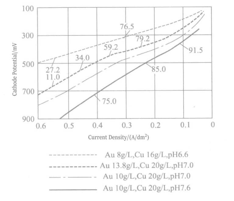
The gold-copper alloy plating layer of EDTA plating solution is heat-treated at 300~400℃ to obtain Au-Cu3 intermetallic compound, which has very high hardness. Figure 1-23 shows the polarization curve of the plating solution in Table 1-4.
3.2 Functional Gold Plating
Table 1-20 Composition and Operating Conditions of High-Purity Neutral Gold Plating Solution
| Compoziție și condiții de funcționare | Nr. 1 | Nr. 2 | Nr. 3 | Nr. 4 | No. 5 |
|---|---|---|---|---|---|
| Potasiu cianură de aur/(g/L) | 10 〜 31 | 10 〜 20 | 7〜18 | 6 | 8.2 |
| Sodium dihydrogen phosphate/(g/L) | 60 | - | 82 | - | - |
| Potassium pyrophosphate/(g/L) | - | - | - | - | 150 |
| Citrate/(g/L) | 60 | 60 〜 125 | 50 〜 75 | 90 | - |
| Potassium Citrate | Potassium Citrate | Ammonium citrate | Soluble salt of acid | ||
| Sodium thiosulfate pentahydrate/(g/L) | 5 〜 10 | - | - | - | - |
| Triethyl phosphate/(g/L) | - | 30 〜 60 | - | - | - |
| Aminotrimethylphosphate/(g/L) | - | - | - | 80 | - |
| Benzyl Alcohol (mass fraction)/% | - | - | - | - | 0. 05 |
| pH | 5. 5 〜 8. 0 | 6 〜 8 | 5 ~ 6. 5 | 6.0 | 7 ~ 8 |
| Temperatură / ℃ | 60 | 60 | 45 〜 100 | 65 | 60 |
| Current density /(A/dm2) | 0. 1〜 1.5 | 0. 1 ~ 0. 3 | 0. 1 ~ 0. 4 | 0. 1 ~ 0. 5 | 0. 1 |
4. Sulfite Gold Plating
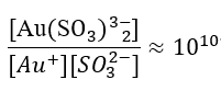
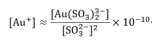
Since 1970, gold plating using gold sulfite salts has been practical. Sulfite gold(I) complex salts undergo [Au(SO3)2]3-⇌Au++2SO32- dissociation.
The stability of this type of complex ion is much lower than that of cyanide complexes, with a stability constant of about 1010, so the stability is 1028 times worse than [Au(CN)2–] .
Am is the amino group of an aliphatic amine.
The anion dissociates according to the following formula:
[Au(Am)2(SO3)2]3- ⇌[Au(Am)2]+ + 2(SO3)2- (1-2)
And also [Au(Am)2]+ ⇌Au+ + 2Am (1-3)
Table 1-21 Composition of Gold Sulfite Electroplating Solution
| Compoziție | Parametrii |
|---|---|
| Gold [iminocoordinated salt of sodium gold(I) sulfite]/(g/L) | 12 |
| Sodium sulfite (free)/(g/L) | 50 |
| Citrat de sodiu/(g/L) | 50 |
| Tetraborat de sodiu/(g/L) | 10 |
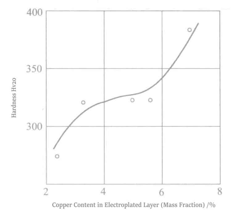
Gold sulfite salt is generally used to plate Au-Pd-Cu ternary gold alloys during gold alloy electroplating. Its advantages are: ① the plating layer appears pink; ② hardness reaches up to Hv 400; ③ excellent wear resistance; ④ excellent corrosion resistance. The disadvantages are: ① the ratio of alloy deposition varies unevenly with current density and temperature; ② the anode undergoes reduction and deposition during long-term plating.
Yoshimura et al. used the conditions in Table 1-22, varying copper concentration of 0.0021~0.0211mol/L, plating solution temperature of 25℃, 50℃ and current density of 0.230A/dm2 for plating. The appearance, hardness, wear resistance, and other values of the deposited coating are shown in Table 1-23. Compared with the grain size 337Å of the gold-palladium alloy plating layer, the grain size 161~231Å of the gold-palladium-copper alloy plating layer is smaller, with a plating hardness of 400 Hv and good wear resistance. There is a related patent for the gold-palladium-copper alloy plating layer.
Table 1-22 Composition of Au-Pd-Cu Alloy Electroplating Solution Unit:mol/L
| Compoziție | Parametru | Compoziție | Parametru |
|---|---|---|---|
| Au(SO3 )2 3- | 0.0204 | Na2SO3 | 0.1983 |
| Pd(en)2 2+ | 0.0236 | NaAsO2 | 0.0115 |
| EDTA-2Na | 0.2109 | CuSO4 | 0. 0021 〜 0.0211 |
Table 1-23 Au-Pd-Cu Alloy Coating and Au-Ni Alloy Coating Hardness and Wear Resistance Comparison
| Electroplating solution composition, deposition ratio/% | Hardness VHN | Wear resistance |
|---|---|---|
| Au : Ni | ||
| 92 : 8 | 237 | 20 |
| Au : Pd :Cu | ||
| 87 : 3 : 10 | 362 | 26 |
| 80 : 5 : 15 | 437 | 33 |
| 79 : 8 : 13 | 383 | 28 |
| 75 : 9 : 16 | 400 | 28 |