How Jewelry Magic Happens: Crafting from Metal to Bling!
Mechanical Processing Technology of Jewelry
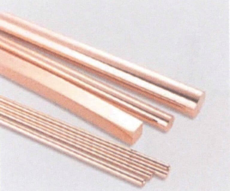
Typical Continuous Casting Copper Profiles
Spis treści
Section I Continuous Casting Profiles
When producing jewelry pieces using mechanical processing technology, it is first necessary to prepare various shapes of blank materials. The traditional production method involves manually pouring the casting ingot mold and opening and rolling the cast blank. This production method generally uses a ladle to pour molten metal into the ingot mold, which inevitably allows the molten metal to be in contact with air for a long time, increasing the chances of oxidation and oxygen absorption; additionally, due to the impact and splashing of the molten metal flow, defects such as air holes and oxidation inclusions occur in the casting. Furthermore, the irregular gradient of the mold and metal during cooling makes defects such as shrinkage, holes, cracks, and surface cold shuts in the casting unavoidable. Due to the aforementioned quality issues in traditional ingot casting, it isn’t easy to produce high-quality products, so improving blank casting technology is crucial.
Due to its advantages, continuous casting technology has become an alternative method to traditional manual ingot mold casting for processing gold and silver. In the 1990s, continuous casting technology was widely applied in the processing of non-ferrous metal profiles and introduced into producing precious metal profiles. The production of non-ferrous and precious metal alloy flat ingots, round ingots, hollow ingots, and thin strips, both domestically and internationally, is almost entirely done using continuous or semi-continuous casting methods.
1. Introduction to Continuous Casting Technology
Continuous casting is an advanced method of continuously pouring molten metal into a special metal mold (crucible), and the cast profile solidifies (forms a shell). It is continuously pulled out from the other end of the crucible. It can obtain cast profiles of any length or a specific length. The crucible’s internal structure also determines the cast profile’s cross-sectional shape.
The continuous casting process is mainly divided into two categories: vertical continuous casting and horizontal continuous casting.
(1) Vertical Continuous Casting
Vertical continuous casting is the earliest developed continuous casting process for jewelry alloys and is still widely used in producing various profiles, especially those with larger cross-sections. Depending on the pulling method, it can be divided into two types: downward pulling and upward pulling, as illustrated in Figures 8-1 and 8-2.
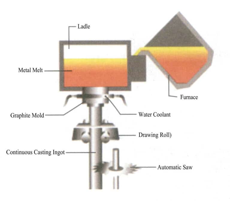
Figures 8-1 The principle of down-drawing continuous casting
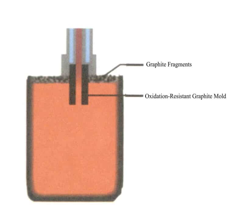
Figure 8-2 The principle of up-drawing continuous casting
(2) Horizontal Continuous Casting
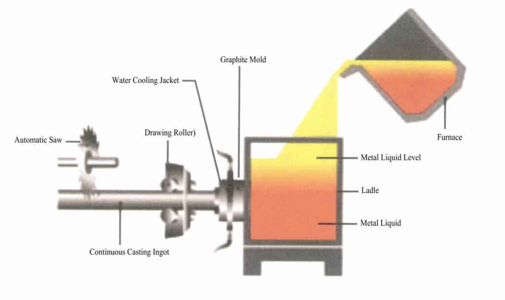
Compared with vertical continuous casting technology, horizontal continuous casting has advantages such as simple equipment, no need for deep wells and cranes, short crystallizers, higher casting speed, ease of mechanization and automation, and the ability for continuous production. However, it is only suitable for producing small specification profiles, and it isn’t easy to produce larger diameter profiles. The principle of horizontal continuous casting is shown in Figure 8-3.
2. Advantages of Continuous Casting
Continuous casting has the following advantages Compared to centrifugal casting and ordinary sand casting.
(1) In the continuous casting process, due to the rapid cooling of the metal, the alloy crystallizes densely, has a uniform structure, and exhibits better mechanical properties. In contrast, in centrifugal casting, the centrifugal force affects the components of the alloy with different specific gravities differently, making the alloy prone to segregation, while in sand casting, the cooling is slower, resulting in coarser grain structure and poor density.
(2) There are no pouring system risers on the castings during continuous casting, so continuous cast billets do not require trimming at both ends during rolling, saving metal and improving yield.
(3) Continuous casting simplifies the process, eliminating modeling and other procedures, thereby reducing labor intensity and significantly decreasing the required production area.
(4) Continuous casting production is easy to mechanize and automate, and during the casting of ingots, continuous casting and rolling can be achieved, greatly improving production efficiency and resulting in lower costs in large-scale production.
(5) The production length of centrifugal casting is limited, and its diameter determines the casting length of the product. Continuous casting is not limited by casting length and can achieve large-scale production in a short period. At the same time, during the centrifugal casting process, the surface oxidation layer is relatively thick, resulting in a significant difference between the casting and final rough dimensions. In contrast, continuous casting can achieve more accurate dimensions.
(6) Centrifugal casting cannot produce products with complex cross-sectional structures according to customer requirements. In contrast, continuous casting can produce various shaped profiles with low-cost control.
3. Categories of Continuous Casting Profiles
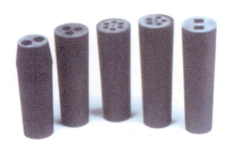
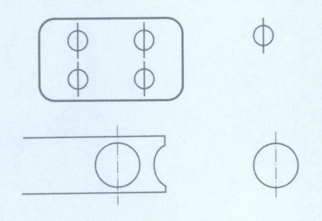
Figure 8-4 Porous Graphite Molds
Figure 8-5 Typical Continuous Casting Copper Profiles
Section II Machining of Sheets, Pipes, and Wires Materials
1. Processing Sheets Materials
Gold bars are pressed into various thicknesses of gold sheets using a press (roller) sheet machine for jewelry processing. For example, gold sheets are needed for making accessories such as bracelet tongue switch, calibration switch and other types.
(1) Główny sprzęt i narzędzia
Press (Roll) machine, scribing pen, iron cutters, and iron pliers.
(2) Kluczowe punkty procesu operacyjnego
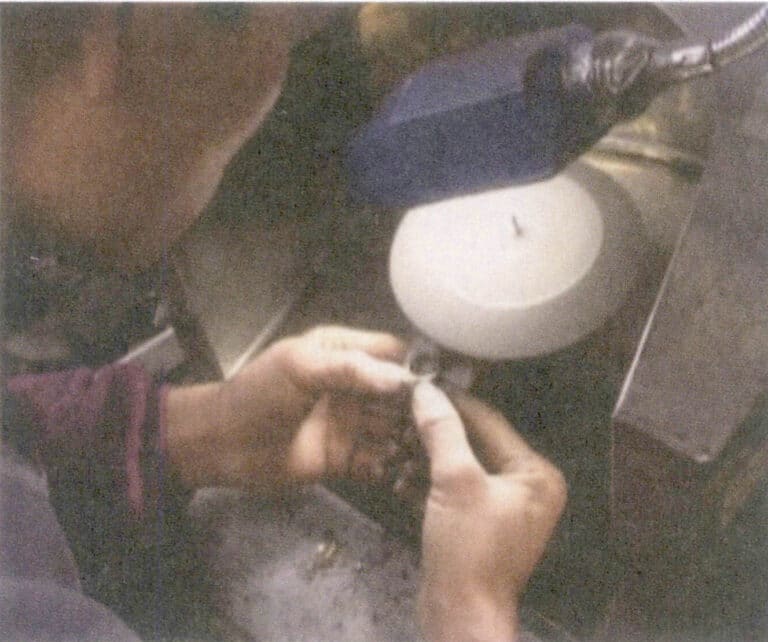
Before pressing, clean the debris on the press machine and the gold bars, adjust the distance between the rollers, and ensure that the distance of each press during the tablet formation is not too large. Determine the number of rolls based on the different gold qualities, and after completing the different pressing counts, perform annealing while controlling the curvature direction of the gold sheet (Figure 8-6). When selecting the rolled gold bars, it is important to master the length and quality to ensure that the pressed gold sheets meet the size requirements.
While making jewelry, many different shapes of gold sheets are often needed. When making, according to the dimensions required by the design drawings, use a scribing pen to draw the shapes on the gold sheet and then cut them into the required shapes with iron cutters. And file away the burrs (mechanical punching can be used for mass production).
2. Processing of Pipe Materials
Pipes are generally made from sheets but exhibit processing characteristics in the form of lines. Slender pipes are produced using a wire drawing machine and wire drawing plate.
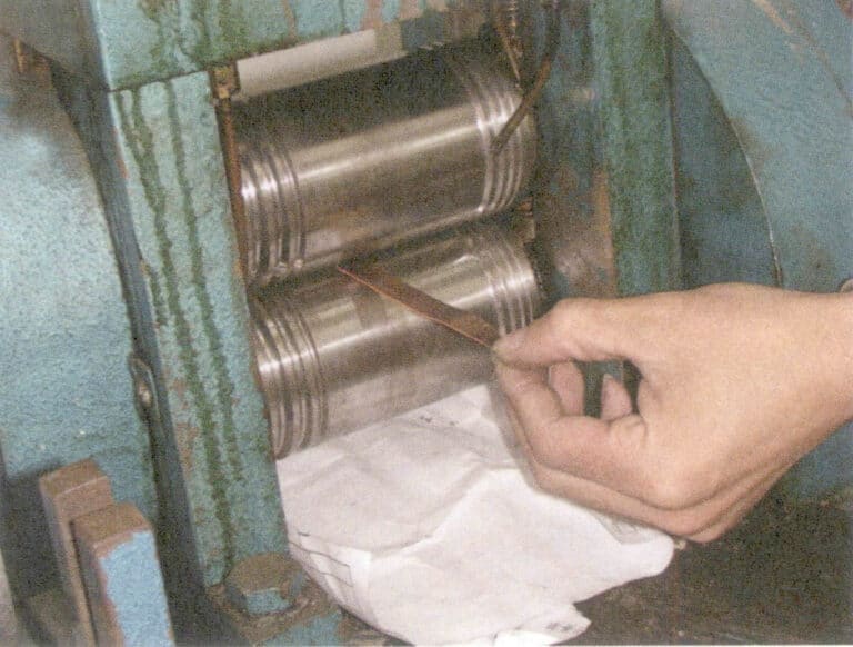
For manual processing of pipe materials, select the appropriate cross-sectional shape and size of the wire drawing plate according to the circumference of the pipe diameter. First, use a press machine to roll the sheet to the appropriate width and thickness, then anneal and slightly flatten both sides. Choose a suitable iron core and use a pit iron and hammer to roll the sheet into a rough pipe shape (Figure 8-7), then trim the ends to allow it to pass through the corresponding size hole in the wire drawing plate (Figure 8-8).
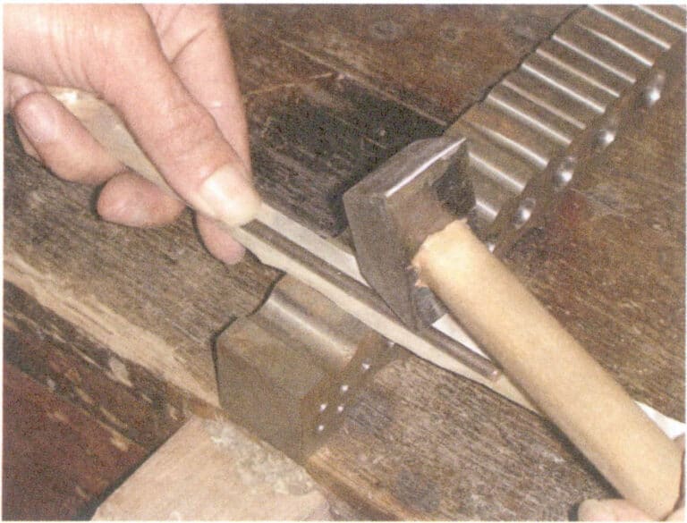
Figure 8-7 Rolling pipe blank
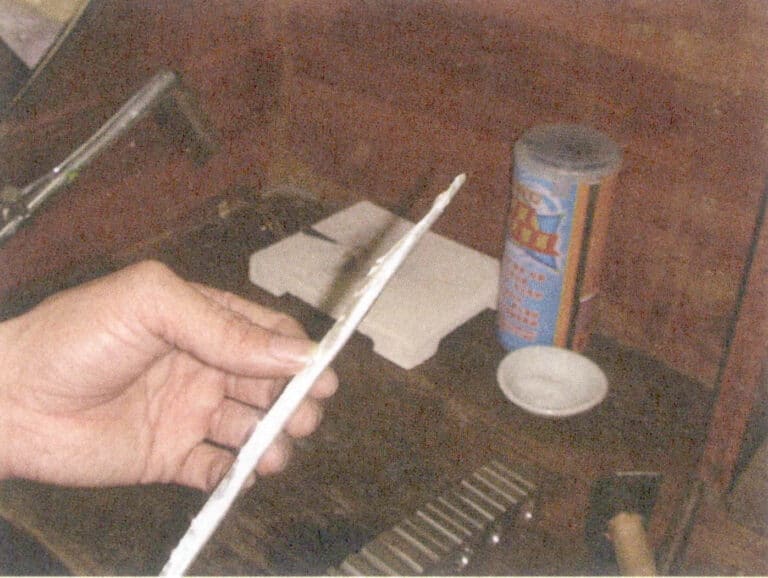
Figure 8-8 Trimming the end of the pipe blank
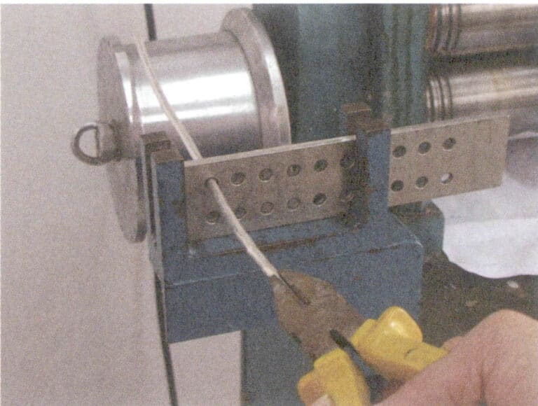
Figure 8-9 Pulling the pipe
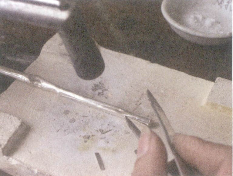
Figure 8-10 Welding the pipe
3. Processing Gold Wire
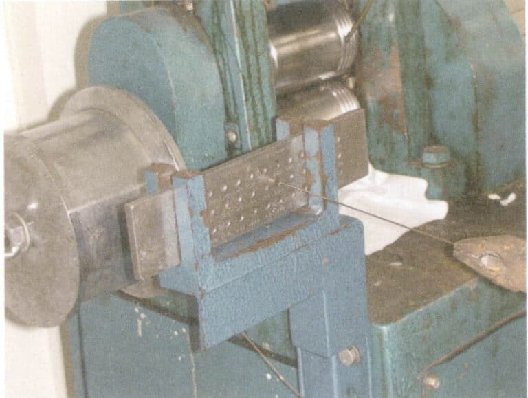
The wire drawing plate is embedded with a series of hard alloy wire drawing holes, and the cross-section of the wire is funnel-shaped, always entering from the large end and exiting from the small end during the drawing process; it cannot be reversed. The drawing plate will be damaged, and the wire quality cannot be guaranteed.
Gold wire can be made into various semi-finished products. Semi-finished products made from wire drawings are widely used in jewelry products. Generally, the K wire drawing process requires several intermediate annealing steps. Typically, one annealing is necessary after drawing through 3〜5 wire grain holes. Radial rings are usually formed using flat-nose pliers on a flat surface, while axial rings are wound around a hard, round wood or steel core. Of course, they can also be shaped into round, pheasant-shaped, hemispherical, etc., as needed.
Section III Stamping Process
1. Characteristics of Stamped Jewelry Parts
(1) Compared to lost-wax cast jewelry parts, stamped parts are thin, uniform, light, and strong. The stamping method can significantly reduce the wall thickness of the workpiece, thereby reducing the weight of the jewelry parts and improving economic benefits.
(2) Jewelry pieces produced by stamping have fewer holes and good surface quality, which improves the quality of the jewelry and reduces the defect rate.
(3) Stamping has high production efficiency, good working conditions, and low production costs during mass production.
(4) When the precision of the mold is high, the accuracy of the stamped jewelry pieces is high, with good repeatability and consistent specifications effectively reduce the trimming, grinding, and polishing workload.
(5) Stamping can achieve a high degree of mechanization and automation.
2. Conditions for Adopting Stamping Technology
Stamping is a relatively advanced processing method that has significant advantages in both economic and technical aspects. The purpose of converting investment-casting jewelry pieces into stamped parts is to improve production efficiency, reduce production costs, and increase economic benefits. However, whether this is feasible still requires specific consideration of the following conditions.
(1) After adopting the stamping process for jewelry, the original performance requirements must not be compromised. The choice of metal thickness is important when producing jewelry using stamping technology. If the thickness is too great, it is difficult to ensure the integrity and precision of the shape, and cracks are likely to occur at the bending points; if it is too thin, it will affect the mechanical strength of the workpiece.
(2) The jewelry should have a considerable production batch. Since stamping requires the creation of specialized molds, which have a longer cycle and higher costs, using stamping methods to replace investment casting for small-batch products does not have cost advantages.
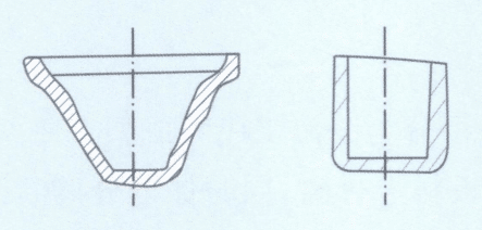
(3) The structure of the jewelry pieces should have good stability. It is advisable to avoid small holes, narrow grooves, and acute angles; structures with hollow bottoms cannot be stamped, and draft angles should be designed. The shape of the stamped parts should be as symmetrical as possible to avoid issues such as stress concentration, eccentric loading, and uneven mold wear.
(4) The alloys used for stamping production must have certain cold-working properties. Jewelry alloys with poor ductility and significant work hardening are prone to quality issues when applying this process.
3. Tools and Equipment Required for Stamping
3.1 Stamping Machinery
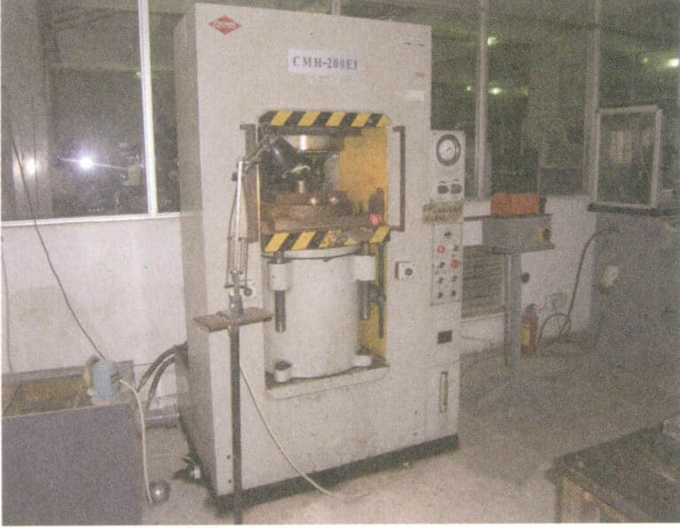
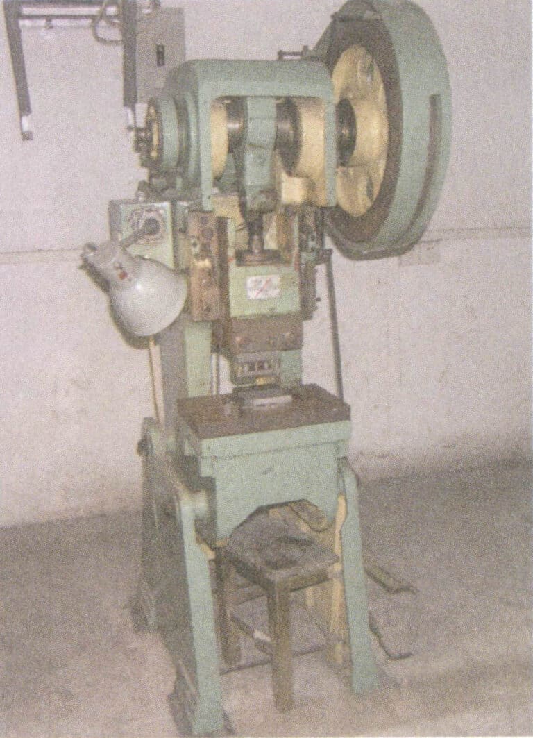
Figure 8-13 Punching power press
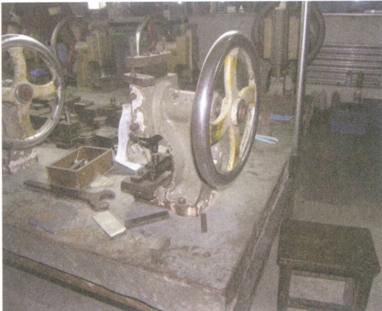
Figure 8-14 Manual press machine
3.2 Stamping Molds
Stamping machinery processes materials by loading stamping molds; stamping cannot be performed without molds. Generally, the design and manufacturing of molds take considerable time, which extends the preparation time for producing new stamped parts. After the initial product design plan is determined, a comprehensive and scientific analysis of its processability must be conducted to ensure a good forming process, which must be the basis for mold production. The molds’ precision and structure directly affect the stamping processing productivity and the stamped parts’ accuracy; the manufacturing cost and lifespan of the molds are important factors that influence the cost and quality of the stamped parts. Therefore, molds play an extremely important role in stamping and can be said to be the “key” to stamping processing.
(1) Types of Molds
There are many methods of stamping processing, such as cutting, bending, twisting, forming, forging, and joining, all of which fall under stamping processing. Correspondingly, many types of molds can be roughly divided into several major categories; different types of molds can perform different operations.
① Cutting processing. This includes punching closed curves, profile cutting and side cutting of open curves, perforating, shearing, notching, partial separation, etc.
② Bending. This includes “V” bending, “L” bending, stepped “Z” bending, “N” bending, hat-shaped bending, cylindrical edge rolling, circular bending, and twisting bending, etc.
③ Twisting and bending. Produce container-shaped products that conform to puncher shapes and die with a bottom.
④ Other aspects. Such as semi-perforating, protruding, punching through, cutting bends, pressing, stamping, trimming, fine punching, etc.
(2) Mold Design
Mold design is the foundation of the stamping process feasibility and mold life.
① Mold structure design. Stamped parts should avoid structures with small holes, narrow grooves, and sharp angles that are difficult to form and demold; the shape should be as symmetrical as possible. Draft angles should be designed to avoid stress concentration and increased stamping unit pressure, overcoming defects such as eccentric loading and uneven mold wear. When designing molds, the functions of CAD systems should be fully utilized to perform two-dimensional and three-dimensional designs of jewelry pieces, ensuring the uniformity and accuracy of the product’s original information, avoiding errors caused by human factors, and improving the quality of mold design.
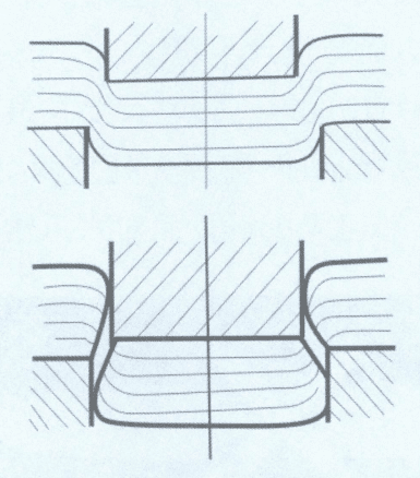
② Mold cavity design. The radius R of the edges and bottom of the mold cavity should be maximized as much as possible while ensuring the cavity is easily filled. If the radius is too small, the edges of the cavity may collapse under high pressure, and in severe cases, it may form an inverted cone, affecting the ejection of the forged part. If the bottom radius R is too small and not smoothly transitioned, it is prone to cracking, which will continue to expand.
③ Mold materials. The choice of materials for molds should be based on the working conditions, production volume, and the inherent toughness of the materials. High-performance tool steels should be selected as much as possible to ensure internal quality and avoid defects such as component segregation and excessive impurities. Non-destructive testing techniques such as ultrasonic testing should be used to check and ensure that each forged part has good internal quality, avoiding potential metallurgical defects and ensuring that the mold has sufficient hardness, strength, and toughness to withstand repeated impacts, fatigue, and wear.
(3) Mold Manufacturing
① Mold processing and forming. Advanced equipment and technology should be used for processing and manufacturing to ensure the precision required for jewelry stamping parts, ensuring that the mold has high precision and that the deformation and residual stress after processing are not too large. The mold cavity’s roughness directly affects its lifespan; high roughness makes it difficult for jewelry pieces to be demolded, especially in areas with raised parts; the deeper the workpiece, the tighter it holds. Additionally, high roughness values increase the resistance to metal flow, affecting the forming of stamped parts and making the mold-prone to early failure. Molds with low surface roughness have less friction resistance and strong anti-biting and anti-fatigue capabilities, with surface roughness generally required to be Ra = 0.4 〜0.8μm. The tool marks and grinding marks left on the mold cavity surface are areas of stress concentration and are also sources of early and fatigue cracks, so it is essential to sharpen the tools before pressing. The cutting amount should be small during finishing, and tool marks are not allowed. For complex mold cavities, sufficient grinding allowance must be left; if grinding overheats, it can cause microscopic cracks that are invisible to the naked eye and are perpendicular to the grinding direction. For the precision grinding of precision molds, attention must be paid to the influence of environmental temperature, requiring constant grinding. The manufacturing and assembly precision of the mold significantly affects its lifespan; high assembly precision, flat bottom surface, good parallelism, high perpendicularity between the punch and die, and uniform gaps are beneficial for improving the mold’s service life.
② Mold Heat Treatment. Mold heat treatment includes annealing after forging mold materials, high-temperature tempering or low-temperature tempering after rough processing, quenching and tempering after finishing, and low-temperature tempering to relieve stress after electrical discharge machining and wire cutting. A good mold lifespan can be ensured only with good coordination between cold and hot processing. Depending on the heat treatment process used, the same mold material can significantly differ in service life; improper heat treatment can lead to early mold failure.
③ Mold Surface Treatment. The quality and hardness of the mold surface significantly impact the mold’s service life and the appearance quality of the parts. Therefore, before using the mold, which is also the final stage of mold manufacturing, grinding, and polishing treatments are usually performed to improve the surface quality of the mold. After grinding and polishing, various surface treatment technologies may also be used to further enhance the mold surface’s hardness, extend the mold’s service life, improve the processing quality of the workpieces, and reduce the mold’s operating costs. Mold surface treatment technologies include cavity carburizing, nitriding, boriding, carbon-nitrogen co-diffusion, local spraying, brushing, and cavity cladding. Among these, physical vapor deposition (PVD), chemical vapor deposition (CVD), and other surface coating hardening technologies, such as vacuum deposition, vacuum sputtering, and ion plating, have significantly progressed in recent years.
(4) Typical Jewelry Mold Manufacturing Process
① Determine the specific plan for mold production based on product structure dimensions and manufacturing processes and identify the type and structure of the mold.
② Cut the purple copper and mold steel materials as needed (Figure 8-15).
③ An iron bed is used to process the surface of the steel and copper materials, and the surface is ground after processing with a grinding machine (Figure 8-16).
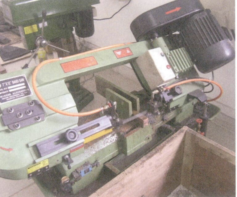
Figure 8-15 Material Cutting
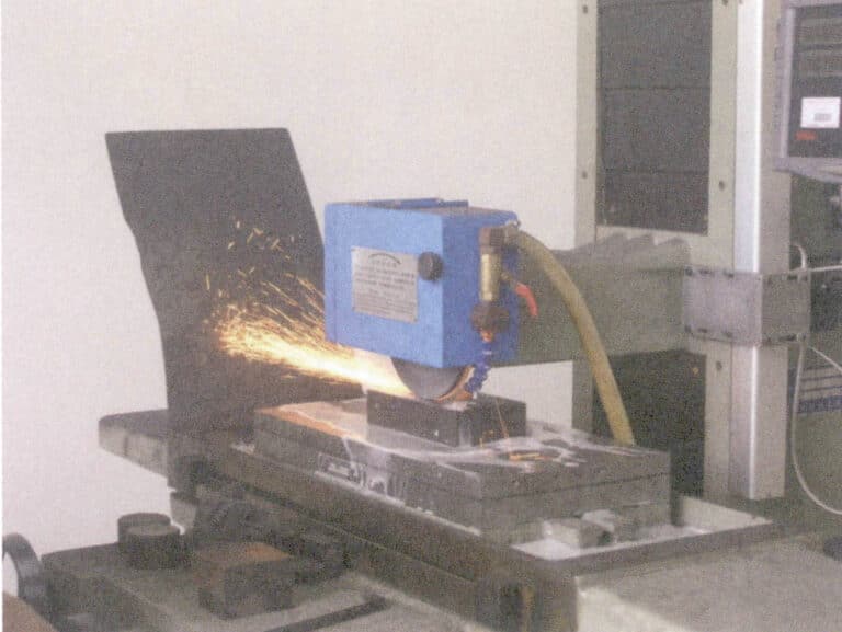
Figure 8-16 Surface Grinding
④ Drawing and programming the cutting path, using a precision engraving machine to mill purple copper material to make a copper electrode (Figure 8-17, Figure 8-18).
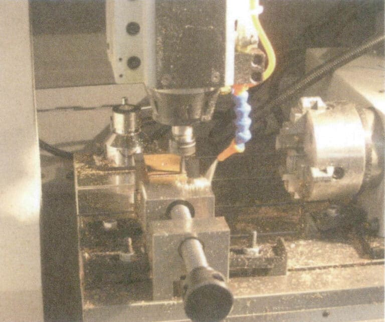
Figure 8-17 Engraving and milling processing
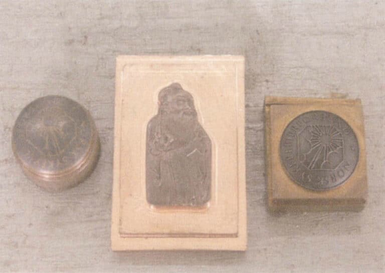
Figure 8-18 Copper electrode
⑤ Processing related components of the mold, such as die shanks, punch pins, etc. (Figure 8-19).
⑥ Marking and positioning the material according to the drawing (Figure 8-20) and drilling holes with a drill press.
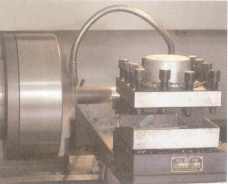
Figure 8-19 Grinding the die shanks
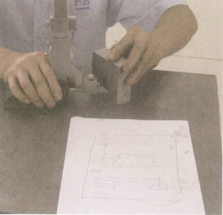
Figure 8-20 Line Positioning
⑦ Heat treatment of the mold steel block (Figure 8-21).
⑧ Computer programming, wire cutting, or electrical discharge machining of mold blocks, punches, inserts, etc. (Figure 8-22).
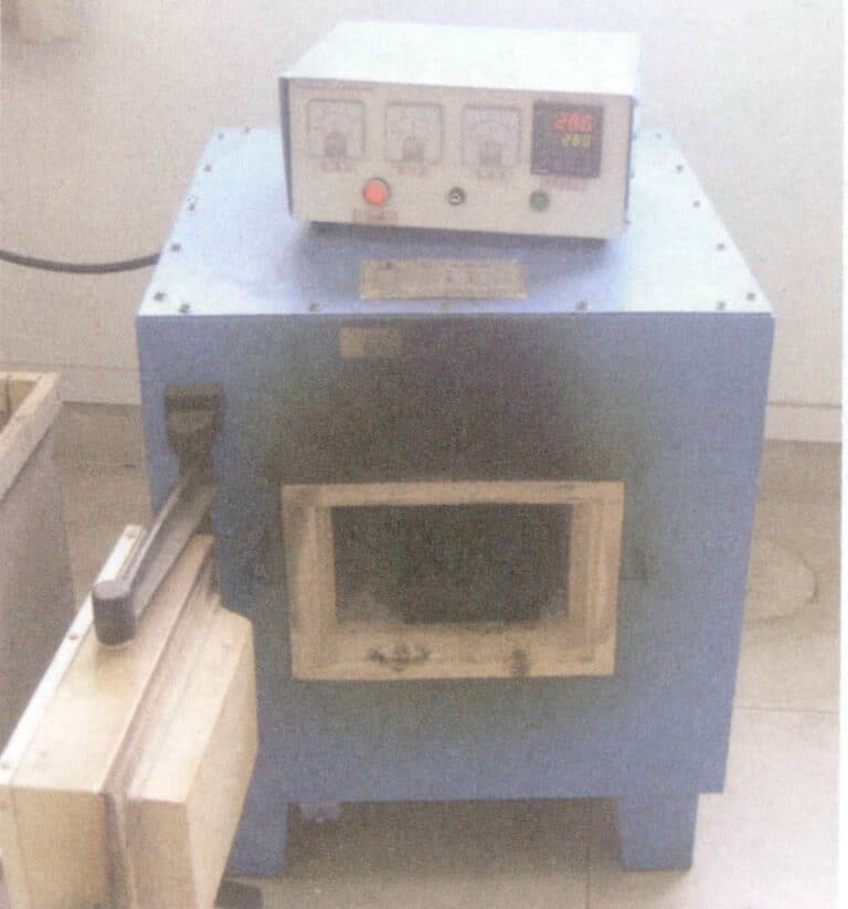
Figure 8-21 Steel Material Heat Treatment
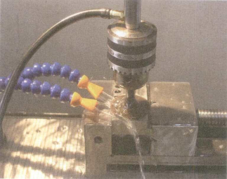
Figure 8-22 Electrical Discharge Machining of Molds
⑨ Assemble the machined mold blocks, die shanks, punch pins, and inserts according to the mold design plan (Figures 8-23, 8-24).
⑩ Test the molds using a punch press, hydraulic press, etc., to determine if the molds are qualified, and modify the molds based on the test results.
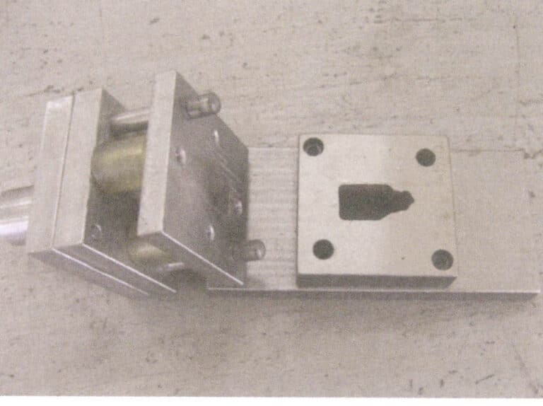
Figure 8-23 Stamping Mold
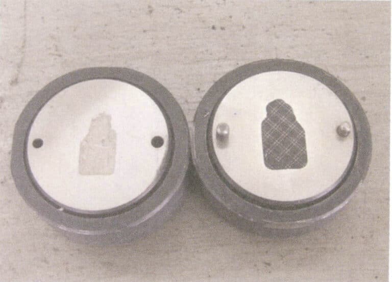
Figure8-24 Oil-Pressure Mold
Copywrite @ Sobling.Jewelry - Producent biżuterii na zamówienie, fabryka biżuterii OEM i ODM
4. Requirements of Stamping Process for Stamping Materials
The surface condition and intrinsic properties of the sheet metal used for stamping significantly impact the stamped products’ quality. The stamping materials should meet the following requirements.
(1) It must meet the performance requirements of the stamped parts. The yield strength of the stamping materials should be uniform, with no significant directional strength, good plasticity, low yield strength ratio, and low work hardening. For some K gold alloys that are prone to work hardening, attention should be paid to intermediate processing when using stamping processes to avoid cracks. Inclusions, harmful elements, and defects such as shrinkage and porosity in the material can easily lead to quality issues in the stamped parts.
(2) It must meet the surface quality requirements of the stamped parts. The stamping materials should have good surface quality, ensuring smooth surfaces without spots, scars, scratches, or cracks.
(3) It must meet the thickness requirements of the stamped parts. The thickness of the stamping materials should be precise and uniform.
5. Stamping Process
Table 8-1 Classification of Stamping Processes and Their Characteristics (According to Fu Hongsheng, 2005)
| Nature of work | Job title | Work Process Flow Chart | Characteristics and application scope | |
|---|---|---|---|---|
| Separation process | Cutting |
|
Cutting off of plates with shears or punching dies, without closing of the cut-off line | |
| Blanking | Blanking and punching |
|
Punching and cutting the sheet along the closed line with a punching die, and the punched part is waste material | |
| Notching |
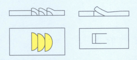
|
Punching of a notch in the blank along an unenclosed line, with bending of the cut part, e.g., ventilation panels. | ||
| Edge cutting |
|
Cutting off the edge of a workpiece | ||
| Forming process | Gięcie |
|
Bending a sheet into a certain shape | |
| Drawing deep |
|
Making a workpiece from a flat blank | ||
| Forming | Undulating |
|
Partial stamping of plates into raised and concave shapes | |
Table 8-2 Three Stages and Characteristics of the Blanking Process (According to Fu Hongsheng, 2005)
| Phase | Charakterystyka | Section Characteristics | |
|---|---|---|---|
| Phase 1 | Sheet in the convex mold pressure, the first elastic compression and stretching deformation; at this time, the convex mold is a slightly crowded sheet, the other side of the sheet is also slightly crowded concave mold edge, convex mold end of the material below a slight bend, concave mold edge above the material began to buckling gap is more prominent, bending and buckling the more serious, the sheet in the convex, concave mold edge at the formation of the initial burr roll of the angle, the material at this time, the internal stress has not exceeded the elastic limit, when the removal of external forces, the material can be restored to its original state. The material can be restored to its original state when the external force is removed. This stage is called the elastic deformation stage. |
|
Initial burr roll, permanent burr roll |
| Phase 2 | Plastic deformation, external force beyond the material's strength limit, resulting in fracture lines, when the convex mold continues to press people, the pressure increases, the stress inside the material is also increased, the stress in the material reaches the yield limit will begin to enter the plastic deformation stage. In this stage, as the depth of the convex mold extrusion into the material gradually increases, the material program's plastic deformation also gradually increases. Due to the existence of the gap at the edge, the internal tensile stress and bending moment of the material also increase, so that the hardening of the material in the deformation zone increases until the material near the edge, due to the tensile stress and stress concentration of the role of the beginning of micro-cracks, at this time, the blanking deformation force also reaches the maximum value. The appearance of micro-cracks indicates that the material begins to damage, and the plastic deformation stage ends. |
|
Generation of bright bands perpendicular to the sheet and initial burr |
| Phase 3 | Fracture separation stage microcracks continue to extend to the material within the overlap extension, the material fracture separation. The Convex continued to fall, producing the upper and lower micro-cracks that continued to expand and extend to the inside of the material; when the upper and lower cracks met and overlap, they began to separate the rough fracture zone, when the convex die down again, will be punched out of the part of the die holes to this point, the convex die back up to complete the entire blanking process. |
|
Produces rough and tapered fracture zone burr initial elongation |
6. The Stamping Process of Typical Jewelry Pieces
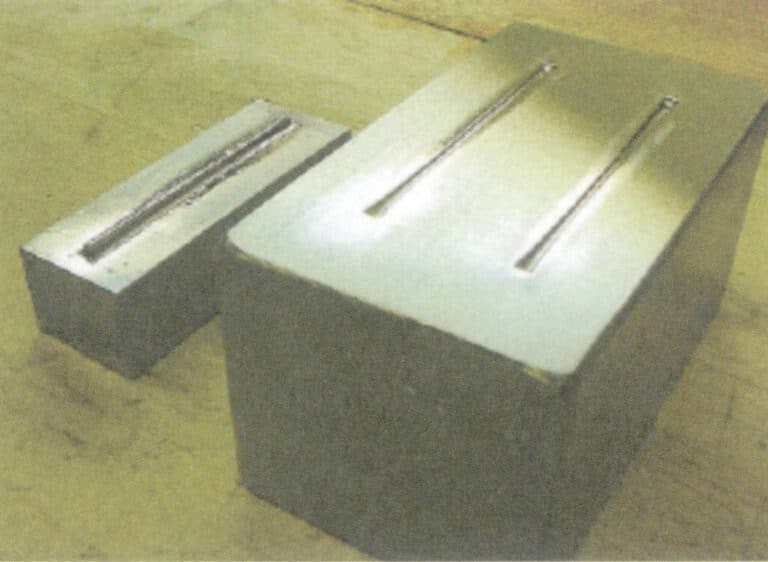
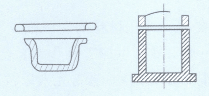
Figure 8-25 Mold for Square Gold Bar Used in Ring Shank (According to Klotz F, 2003)
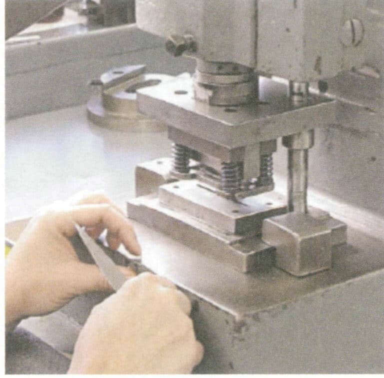
Figure 8-26 Mold Assembly (According to Klotz F, 2003)
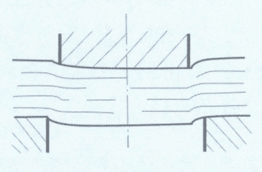
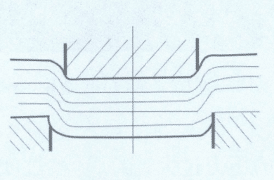
If the pressure is too high, the metal sheet will be excessively impacted, causing the mold to easily crack at the bottom or the walls to collapse. It can split the mold in half like a wedge in severe cases. Additionally, the amount of metal sheet is also very important; if too much material is added, the workpiece will have burrs. To continue processing the material, a trimming tool must be used to remove the burrs. Conversely, if the added material is insufficient, the mold cannot be filled, and the stamped part cannot be formed.
During the work process, it is important to strengthen the maintenance of the trimming tool, as it is crucial for the shape conformity and stability of the workpiece. If the cutting blade of the trimming tool is too sharp, the opening will enlarge, causing steps in the trimming area. Conversely, too tight will cut into the workpiece, resulting in flat edges that do not match the design.
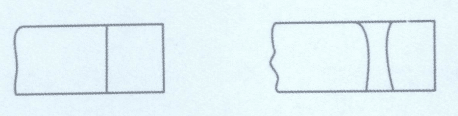
After obtaining a straight rectangular metal strip through punching, the required external dimensions must be stamped out in the final mold to form the desired ring shank. Before rounding the ring shank, the two ends must be processed first to accommodate the bezels (Figures 8-27, 8-28). For a four-claw setting, the end of the ring shank is cut to an angle of 90°, while for a six-claw setting, the end of the ring shank is cut to an angle of 60°.
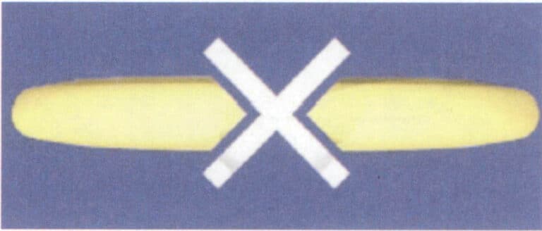
Figure 8-27 For a four-prongs setting, the end of the ring shank is cut to an angle of 90° (According to Klotz F, 2003)
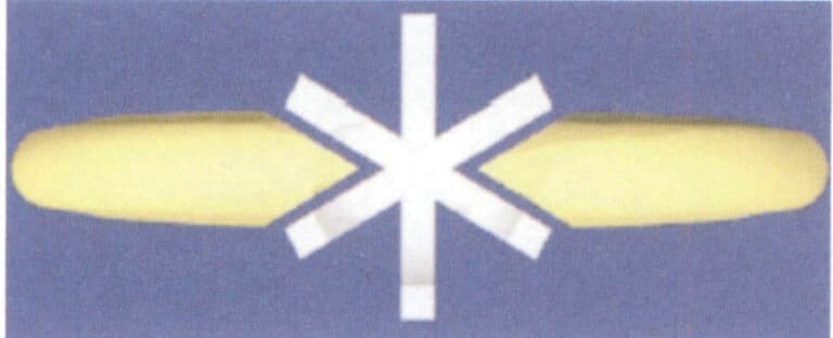
Figure 8-28 For a six-prong setting, the end of the ring shank is cut to an angle of 60° (According to Klotz F, 2003)
There are generally three methods for making the slanted end of the ring shank: one simple method is to use a punch and a metal plate to chisel it out, but the quality of the chiseled setting is relatively poor. Another method is to grind the setting position on a horizontal grinding machine, fix the ring shank in a fixture, and allow the grinding wheel to operate for accurate and neat grinding, which is a better method. The third method is to bend the end of the ring shank into a hook shape (Figure 8-29), then clamp and grind it. This is similar to the second method but can avoid deforming the setting position at the end of the ring shank during bending, as the accuracy of the setting position is crucial for repeatability. When using the latter two processing methods, attention must be paid to the grinding angle, which is very important to ensure the precise fit between the setting position and the bezels so that there are no gaps between the two.
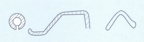
Rounding comprises a series of bending steps, and care must be taken to protect the end of the ring shank, as this position directly relates to the fit of the setting. The rounding method is simple; it can be done with two half-round steel dies. Sometimes, to avoid forming deep impressions on the workpiece, a plastic block is embedded in the area of the first steel die that contacts the workpiece (Figure 8-30). The final bending shape is formed in the second steel die.
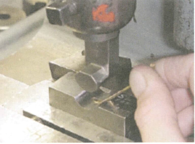
Figure 8-29 Bending the end of the ring shank (according to Klotz F, 2003)
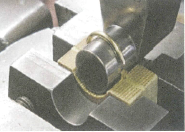
Rysunek 8-30 Zaokrąglanie trzonu pierścienia (według Klotz F, 2003)
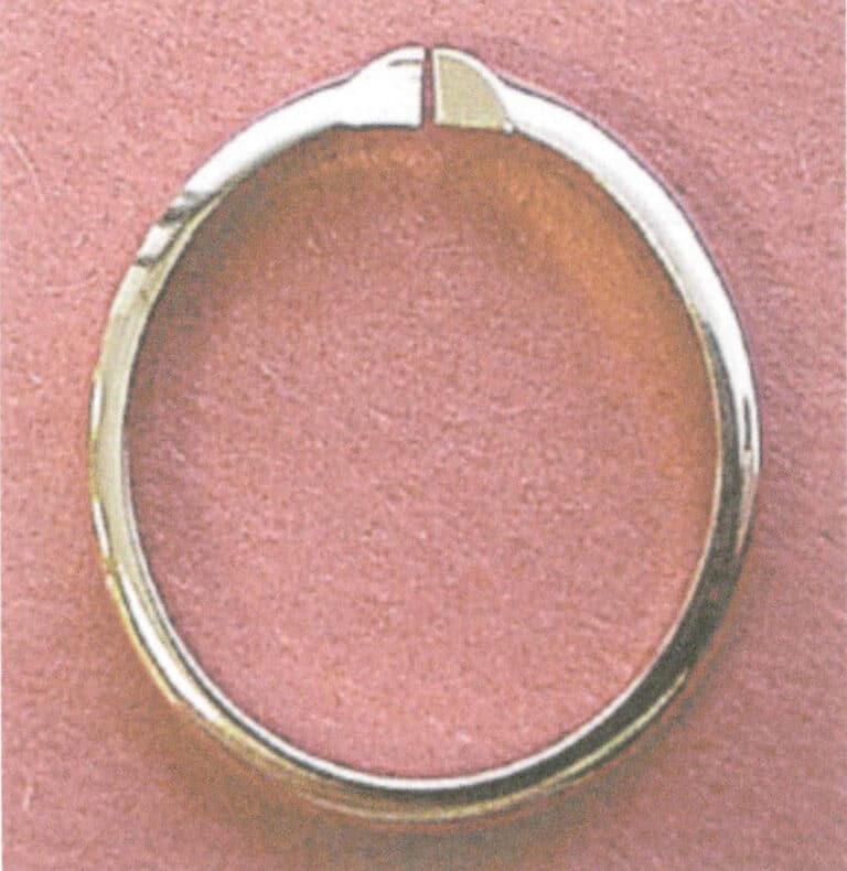
Figure 8-31 The ring shank after full round polishing (According to Klotz F, 2003)
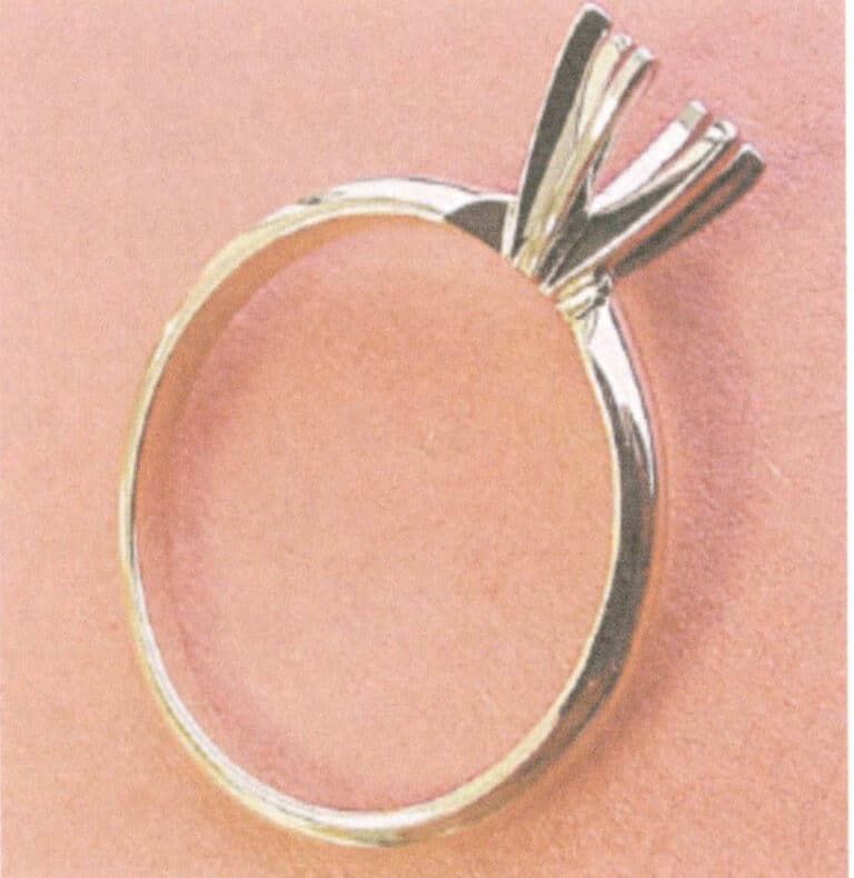
Figure 8-32 The assembled ring (According to Klotz F, 2003)
7. Common Quality Issues in Stamped Jewelry Parts
(1) Defects Arising from Casting Ingots or Continuous Casting Blanks
① Central shrinkage and shrinkage holes. The depressions at the top of the ingot result from solidification shrinkage, which can cause the processed plates, strips, or wires to split along the centerline defects during subsequent processing (forging or rolling). This issue is particularly likely to occur when the surface of the depressions has oxidized, and this defect is also known as crocodile cracking. To avoid this defect, the depressed areas should be cut off before processing, and internal shrinkage holes should be welded. Generally, if the inner surface is clean and free of oxides, it can be welded to eliminate the issue.
② Blistering. Blistering on the surface of plates and strips may be caused by gas holes within the ingot or reactions between the ingot and the atmosphere during annealing. This issue can generally be avoided by controlling the casting or annealing conditions. For example, it enhances deoxidation during the melting process, reduces gas absorption and oxidation of the molten metal, controls the annealing temperature, and avoids using hydrogen-rich annealing atmospheres.
③ Inclusions. Inclusions in the ingot are non-decomposable particles, such as oxides and silicates, which can cause cracks during processing. There are multiple sources of inclusions; to reduce them, it is necessary to regularly check the condition of the crucible and furnace lining and the cleanliness of the working environment and consider possible reactions during melting.
④ Contamination. Contamination of metals can lead to brittleness or cracks during processing. Introducing trace amounts of lead in recycled or welding materials can contaminate alloy materials. Other brittle contaminants include silicon, sulfur, and other low-melting-point metals. It is important to manage recycled materials carefully; materials with unclear compositions should not be used indiscriminately and should be analyzed first to check for such impurities.
⑤ Surface quality. The final product’s surface quality depends on the initial ingot’s surface quality. Suppose the surface of the initial ingot has oxides. In that case, they should be removed by acid immersion before processing, as these oxides become very difficult to remove once pressed into the surface of the rolled material. Using excessive machine oil or flux in the mold can cause large depressions on the surface of the ingot when a large amount of molten metal enters the mold. A continuous thin film of oil should be brushed on the mold wall, and excess solvent should be removed before pouring. During pouring, if the molten metal contacts the mold wall, oxidation on the surface can form metal beads, which do not fuse well with the metal body, leading to delamination on the oxidized surface during processing and an uneven surface.
Before processing, the surface of the ingot should be checked, and if necessary, it should be filed to ensure it is flat, without depressions or metal beads, and any particles embedded in the metal surface should be removed.
(2) Defects Occurring during the Rolling of Plate, Strip, and Sheet Materials
① Poor quality of the finished product rolls. When the surface of the finished product rolls has scratches or local damage, the surface quality of the rolled material will deteriorate. The diameter of the finished product rolls should be small, and the surface should be polished or electroplated to achieve a mirror effect. During production, the surface of the rolls should be frequently wiped to prevent dust and other particles from accumulating, which could scratch the rolls or the surface of the rolled strip. The rolls should be covered to protect the surface when not in use.
② Rolls are not straightened. If the rolls are not straightened and thicker strips are being rolled, it will cause them to bend to one side. If the strips are thinner, it will create jagged edges on one side. The screws of the rolls should be adjusted to ensure the gaps are straight.
③ Rolls are bent. If the rolls bend under the rolling pressure, it will lead to uneven thickness of the strip cross-section or jagged edges on both sides. The amount rolled each time should be reduced, and the number of intermediate annealing processes should be increased to reduce rolling force. Four rolls can also be used, with small-diameter rolls supported by larger-diameter rolls, which helps improve the rolls’ resistance to bending.
④ Edge cracks. Usually caused by excessive processing between two annealing cycles, they should be promptly repaired when edge cracks appear. During further rolling, some cracks may suddenly expand to the center of the strip, leading to product scrap.
⑤ Thickness control. During the rolling operation, it is essential to ensure that the thickness of the rolled material is uniform in both length and width directions. Variations in thickness can lead to changes in rolling force during the subsequent sheet-forming process, thereby increasing the scrap rate and exacerbating tool wear and damage.
(3) Defects Occurring during the Rolling of Bars
The main defects are fins and stacking. Fins are caused by pushing too much metal into the gap between the rollers, meaning that the reduction amount attempted at one time is too large, causing the rollers to be pushed apart, and excess metal is squeezed to the sides, forming fins. If the fins are subsequently rolled into the bars, they will stack, creating weak points prone to cracking during later processes, especially during twisting or bending, where cracks are more likely to occur. An appropriate reduction amount and rolling 90°in sequence will help prevent this defect.
(4) Defects that Occur during Wire Pulling
The most common defects in wire drawing are breakage or necking, with four possible causes.
① The drawing amount is too large and requires intermediate annealing.
② Inclusions appear on the wire, becoming weak points.
③ Each drawing amount is too large for large-diameter bars; based on the material’s ductility, each time, cross-section reduction maybe 25% ~ 45%, but with the reduction in diameter, it should be reduced to 15% ~ 20%.
④ A lubrication interruption during the drawing process increases the friction between the wire and the groove, further reducing the allowable processing amount each time.
(5) Annealing Defects
Suppose the annealing time of the workpiece is too long. In that case, the annealing temperature is too high, or both will lead to excessively large grains, causing the workpiece to form an orange peel surface when deformed, making it difficult to polish to a qualified state.
Stamping (oil) process video