ja 日本語
ジュエリーのためのプロの金電鋳法を学ぶ。メッキ液を使って、中空で複雑な18K金合金のペンダントや装飾品を作ります。電流密度と熱処理をコントロールして、丈夫で耐食性に優れた高品質の特注品を作ります。デザイナーやブランドにとって不可欠です。

金の電鋳と特殊素材への応用とは?

Understanding Gold Plating: Techniques, Benefits, and Applications

はじめに

Electroforming is an advanced electroplating-based manufacturing process that creates freestanding metal parts, primarily using gold and its alloys. Unlike conventional plating, it focuses on building thick, precise layers which are then separated from the substrate. The text explains how specific plating solutions and methods, like simultaneous or sequential deposition, are used to create complex gold alloy items such as decorative pieces and dental crowns. It also details why special surface preparations are crucial for plating challenging materials like stainless steel and titanium, addressing their passivation layers to ensure adhesion and functional performance in applications from electronics to aerospace.

金の電気鋳造とは何か、そしてそれが特殊材料にどのように適用されるか

金の電気鋳造とは何か、そしてそれが特殊材料にどのように適用されるか

目次

Section I Electroformed Gold and Gold Alloys

Electroforming is a manufacturing process based on metal electroplating, which is different from electroplating aimed at coating materials. The difference in electroforming is that various methods separate the material after electroplating, and the product is only the metal electroplated layer. Although it may seem similar to electroplating, electroforming is more advanced and requires higher electroplating technology. Especially in terms of the plating layer’s current distribution and internal stress, it is more specialized than electroplating.

Since its inception, electroforming has a history of more than 100 years. In 1840, Dr. F. V. W. Netto first published a paper on electroforming, using copper plating solution to create dense copper replicas on flat or three-dimensional objects, modeling, similar models, printing, or casting.

Currently, the materials used in electroforming are mainly copper and nickel, with small amounts of additives added to high-concentration plating solutions for electroplating. The rise of electroformed gold has been a recent development, but truly ideal electroforming gold plating solutions do not yet exist.

1. Gold Plating for Electroforming

There are many types of plating solutions for electroforming. The commonly used plating solution is cyanide plating solution, while others include sulfite, chloride, or mixed solutions of these compounds. Generally, citrate plating solutions used for electroplating cannot be used for electroforming. Up to now, electroforming has still used the gold plating solution invented by Reid & Goldie (Table 1-118). These plating technologies have historical limitations and have certain practical issues. Rogers obtained a 100~125μm/h gold plating layer from a plating solution containing 14.1g/L potassium gold cyanide, 18.3g/L potassium cyanide, 14.1g/L potassium carbonate, and 11.4g/L boric acid under the condition of temperature 65℃, 3.2A/dm2 (however, according to electrochemical equivalent calculations, even if the current efficiency reaches 100%, only about 60μm plating layer can be obtained). In 1967, Japan and the UK obtained 7 kg of electroformed gold from a neutral plating solution (pH 6.5) of potassium gold cyanide containing 28~36g/L gold, neutralized with phosphoric acid.

In sodium, potassium, or ammonium ion type sulfite electroforming gold solutions, adding gold deposition grain refiners (DOS 2249658, 1972) containing arsenic compounds for electroforming can produce 600μm gold layer.

Table 1-118 Composition and Operating Conditions of Electroforming Solution
Cyanide Plating Solution Operating conditions

1. Potassium gold cyanide

Free potassium cyanide

Dipotassium hydrogen phosphate

温度

Current Density

Stirring

6. 8 〜 10g/L

31g/L

31g/L

50 〜 60℃

2. 5 A/dm2

Cathodic stirring

2. Potassium gold cyanide

Potassium ferricyanide

Potassium cyanide

温度

Current density

30g/L

200g/L

7. 5g/L

85 ℃

3 〜 5

3.Potassium gold(II) cyanide

Potassium cyanide

Turkish red oil

温度

Current Density

30g/L

70g/L

0. 5mL/L

60 〜 65℃

0. 4 〜 1 A/dm2

4. Potassium gold cyanide

Potassium cyanide

Potassium hydroxide

Potassium sulfamate

4-Hydroxy-3-methoxybenzaldehyde

温度

Current density

18g/L

120g/L

4g/L

4g/L

4g/L

80℃

0. 5 〜 1. 8A/dm2

Chloride Plating Solution Operating conditions

Gold (as chloride)

塩酸

Sodium chloride

硫酸

温度

Current Density

25 〜 40g/L

23. 8 〜 55g/L

10 ~ 30g/L

10 〜 20g/L

23 ℃

8. 6 〜 11. 0A/dm2

Cyanide Chloride Plating Solution Operating conditions

Gold (as chloride)

Potassium ferrocyanide

Potassium carbonate

温度

Current density

10g/L

40g/L

40g/L

30 〜 50℃

0. 1A/dm2

Acid Plating Solution Operating conditions

Potassium gold cyanide

Ethylguanidine

Formic acid (85%)

рH

温度

Current density

30g/L

10g/L

250g/L

4. 0

50℃

0. 2A/dm2

Cyanide-free plating solution Operating conditions

Sodium gold sulfite

Potassium phosphate

Sodium sulfite

Arsenic trioxide

рH

温度

Current density

10g/L

30g/L

50g/L

30mg/L

9 〜 10

90℃

0. 1 〜 0. 6A/dm2

Alloy Electroplating Solution Operating conditions

1.Au-Cu alloy plating solution

Au (in the form of gold potassium cyanide)

Cu (in the form of Na2Cu EDTA)

Cu (in the form of Na2Cu EDTA)

プライベートオファーリング4-3 (in the form of 85% HPO3)

Sodium sulfite

рH

温度

Current density

Precipitation rate

Anode

Alloying ratio of Au

(1)

6 〜 6. 5g/L

16 ~ 18g/L

-

25mL/L

-

7. 0 〜 7.5

65℃

0. 6 〜 0. 6 A/dm2

10 〜 12. 7μm/h

プラチナ

55% 〜 95%

(2)

6 〜 6. 5g/L

-

16 〜 18g/L

25mL/L

6 〜 8mL/L

7. 0 〜 9. 0

65℃

0. 6 〜 0. 6A/dm2

10 〜 12. 7/μm/h

プラチナ

55% 〜 95%

2. Au-Cu-Cd alloy plating solution

Au (in the form of potassium gold cyanide)

Cu (in the form of copper potassium cyanide)

Cd (in the form of potassium cyanide cadmium)

Ag (as potassium silver cyanide)

Free potassium cyanide

рH

温度

Current

Current density conditions for plating:Cathode current density

Plating time

Anode current density

Plating time

-

1 〜 3g/L

6 〜 13g/L

0. 1 〜 0. 8g/L

0. 01 〜 0. 1g/L

3 〜 8g/L

9 〜 11

60 〜8 0℃

PR Method(Cathode 60s, Anode 4s)

0. 5 〜 1. 5 A/dm2

4 〜 20s

1.0 〜 3. 0A/dm2

0. 5 〜 2s 18K Au-Cu-Cd Alloy Plating

2. Electroforming Methods

Common methods for gold alloy electroforming are: ① the simultaneous deposition method and ② the sequential deposition method.


(1) Simultaneous Deposition Method

This method involves alloy electroforming by depositing gold and 2 or 3 other metals simultaneously. The composition of the deposited alloy depends not only on the plating solution composition but also on current density and temperature. To maintain a certain alloy deposition ratio, the plating thickness must reach 100~300μm. When electroforming alloys, such as to ensure the consistency of the precipitation of electroforming 18K gold-copper-cadmium ternary gold alloy, the whole process of computerized management of electroplating is carried out in a way that the temperature of the plating solution and the concentration of metal ions are automatically controlled by sensors and the computer monitors the full current and the surface area of the product.

After electroplating the gold-copper-cadmium alloy electroformed layer must be heat-treated in an inert gas atmosphere. The investment in treatment equipment is very large (the composition of the plating solution is the same as the two types of gold alloy plating solutions in Table 1-118).

In recent years, due to environmental concerns about cadmium and the complexity of heat treatment, alloy components other than gold generally only use silver. Using the conditions in Table 1-119, gold-silver alloys from 8K to 18K are electroformed. Japanese patent Showa 58-130293 obtained gold-silver alloy electroplated layers with minimal composition variation and thickness of 150μm.

Table 1-119 Composition and Conditions of Plating Solution for Simultaneous Deposition Electroforming of 8K Gold-Silver Alloy
Composition and Operating Conditions Parameters

Potassium gold cyanide

Potassium silver cyanide

Wetting agent

Potassium cyanide

Telluric acid

pH

温度

Current density

9g/L

4. 5g/L

1mL/L(partially esterified with phosphoric acid)

80g/L

2g/L(TeCl 4g/L, in the form of KTeO)

11. 0

40℃

1.0A/dm2 (100μm platable 100/μm 12K Au-Ag alloy plating)

US PAT. 3427231 by Lechtzin records experimental results, including the PR electrification method (cathode 60 s – anode 4 s). Swiss patent CH 529843 uses a PR method with a cycle ratio of 5 to 10 to 1.

US PAT. 3427231 describes the effect of using ultrasound in electroforming, where the current density can be increased to above 100A/dm2 , and by using ultrasonic stirring and filtration, additives can be avoided.


(2) Sequential Precipitation Method

This method causes the various components in the electroformed alloy to precipitate sequentially, with cycles ranging from one to several tens or hundreds of times. The precipitates form multilayers of different metals. After heat treatment of the precipitates, the metal components diffuse into each other to form a uniform alloy. Heat treatment is performed for alloying after electroplating a certain coating thickness using the plating solution and conditions in Table 1-120.

Table 1-120 Composition and Conditions of the Plating Solution for the Sequential Precipitation Method
Composition and Operating Conditions Parameters

Au (as potassium gold cyanide)

Ag (as potassium silver cyanide)

Cu (as potassium copper cyanide)

KCN

Potassium bicarbonate

pH

温度

6g/L

0. 5g/L

35g/L

5g/L

100 g/L

9.0

60℃

Using the above plating solution as the basic condition, vary the current density to repeatedly plate two types of alloys. After plating a 300μm two-layer composite coating, heat diffusion treatment of 800℃ for 30min, can obtain an 18K gold alloy of Au75%-Agl2%-Cul3%.

(1)Conditions for electroplating gold-silver alloy

Current density 0. 5A/dm2

Thickness of the electroplated layer 0. 8μm(4min)

(2)Conditions for electroplating gold-copper alloy

Current density 1. 2A/dm2

Thickness of the electroplated layer 0. 64μm (4min)

Composition of precipitates: Au 82%

Ag 16%

Cu 2%

Composition of precipitates: Au 65%

Ag 5%

Cu 30%

The gold alloy plating obtained by this method has the following advantages:

① The composition of the gold-silver-copper alloy can be adjusted arbitrarily.

② The hardness of the gold-silver-copper alloy after heat diffusion is much higher than that of ordinary electroplated layers.

③ Good corrosion resistance. The gold-silver-copper alloy electroplated layer is not an alloy but a eutectic-plated layer. After heat diffusion, it is fully alloyed, with corrosion resistance equivalent to metallurgically manufactured alloys, significantly higher than gold-silver or gold-copper electroplated layers.

④ No use of gold-copper-cadmium alloy plating solution. The plating solution for the 18K layer contains no cadmium, making it environmentally friendly and safe.

3. Applications of Electroformed Gold

(1) Uses of Pendants and other Decorative Items

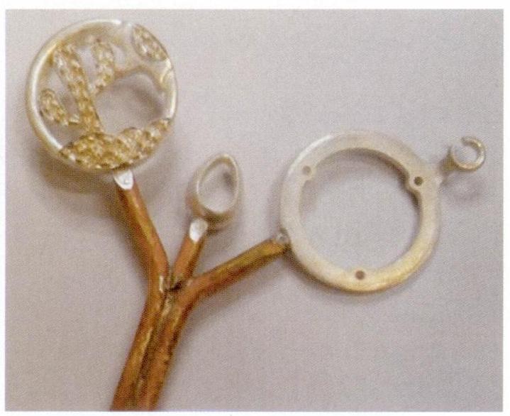
US PAT. 446421 Small hollow globe made by electroforming ball-shaped injection molded objects. After electroforming, small holes are made in the globe, and the plastic inside the globe is removed by heating to obtain a hollow metal sphere. This patented method involves sequentially electroplating copper, silver, gold, and other metals, followed by heat treatment alloying to produce the product.

GB PAT. 2031024 After electroforming real flowers, place them in an electric furnace for heat treatment for 24 hours, then use high-pressure water to blow from the top of the flower stem to remove residues, obtaining electroformed flower decorations.

Other patents, such as the Japanese patent (Showa 59-80788), detail the method of manufacturing gold alloy watch exterior parts using electroforming. The manufacturing method of gold pendants is shown in Table 1-121.

Table 1-121 Manufacturing Methods of Gold Alloy Decorative Items
ステップ 方法
モデル

(1) Make decorations from paraffin according to the design, cast the model in silver, and finish it. Injection molding after making a rubber model out of a silver model

(2) Casting the necessary number of models. At this time, we mainly use Pb-Zn-Bi alloy and Zn alloy (Zn96%-A14%).

Pre-treatment

(1) Must remove the paraffin wax, metal substrate surface burrs and bumpy surface, otherwise affect the final quality of the product

(2) When the material is paraffin, surface semiconducting must be carried out, there are the following two methods

① plastic plating, chemical copper plating metallization

② coated with conductive nitro lacquer, impregnated surface conductivity

Basic Plating

(1) when the substrate is metal, polished and plated with acidic copper. The purpose is to plug the substrate on the sand holes, pores, etc.

(2) For paraffin material, it is necessary to add a base layer of metal if gold is electroformed directly after conductivation. Since paraffin wax is watery at a melting point of about 70°C, the temperature of the plating solution must be ensured to be about 40°C. Otherwise, it is not possible to electroform gold directly on paraffin wax.

Electroformed gold

The most commonly used plating solution is the Au-Cu-Cd alloy solution. The following is the alloy plating process

Plating solution composition.:

Au 6g/L Plating solution temperature 70℃.

Cu 45g/L Current density 0.5~2A/dm2

Cd 1g/L Current efficiency 1.5A/dm2 , 1pm/min

KCN 18g/L Composition of alloy:Au 5%

pH 10 Cu 13%

Cd 7%

During the electroplating of ternary alloys, changes in current density cause significant variations in current efficiency and the deposition ratio of gold, so it is essential to strictly control the metal concentration in the plating solution and the current density during electroplating.
Post-processing

(1) electroforming gold, must use nitric acid, hydrochloric acid and other inorganic acids to dissolve the alloy. After dissolution in the inert gas, 400 ~ 500 ℃, 30min heating treatment, to eliminate the internal stress in the product

(2) Closed hole with gold alloy welding material

Fine finishing Fine grinding of parts, the surface of the whole plating
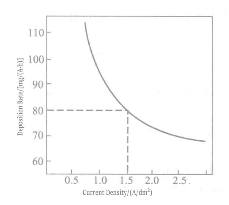
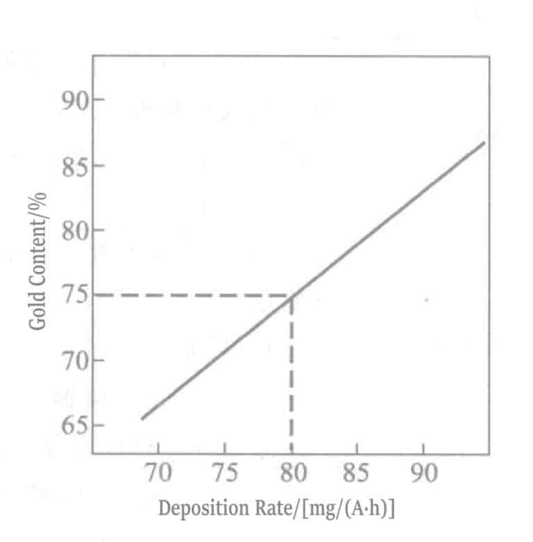
The relationship between current density, gold content, and deposition efficiency of electroplated gold-copper-cadmium alloy is shown in Figures 1-107 and 1-108.
Figure 1-107 Relationship between current density and deposition rate

Figure 1-107 Relationship between current density and deposition rate

図 1-108 金含有量と沈殿率の関係

図 1-108 金含有量と沈殿率の関係


(2) Dental Use

Dental crowns and prosthetic teeth have complex shapes and thin thicknesses, requiring high strength and corrosion resistance. Besides medicine, they also involve technologies from many other disciplines. Rogers, Vr-ijhoef, and others have proposed many research reports on these specialized technologies.


(3) Functional Purpose Detection Equipment

Functional testing involves equipment related to electronics, instruments, communications, and other fields.

X-ray Photomasks                         Nippon Patent Showa 58-224427

                                                Nippon Patent Showa 58-200535

Infrared Filter Gratings                 G. Chanin

Spiral Micrometer                       Young Ogbum

Protruding pad lines                    US PAT.4125441

Spiral micrometers manufactured by the American Standards Bureau implement alternating gold and nickel plating. Since the thickness of the plating layer can be controlled and measured by the current, it can be used for the calibration of electron microscopes.

Section II Special Materials Gold Plating

1. Stainless Steel Electroplating

Due to a passive oxide film on the surface, stainless steel has excellent corrosion resistance. However, electroplating on the passive film of stainless steel is very difficult. Currently, a method with excellent precipitation bonding strength involves precipitating an ultra-thin nickel layer in an impulse nickel plating solution while activating the stainless steel, and the gold layer plated on the impulse nickel layer can be completely and tightly bonded. However, this method has significant drawbacks, severely reducing the corrosion resistance of stainless steel. The following are key issues in electroplating a corrosion-resistant gold layer on stainless steel.

① Do not use a nickel plating intermediate layer; directly electroplate gold on stainless steel.

② Do not use hydrogen halide acids to promote pore formation (hydrochloric acid activation is prohibited).

③ Ensure good adhesion.

To meet the above requirements, in 1971, the HAu(CN)4 manufacturing method and the HAu(CN)4 adjustment method of range of Plating solutions were developed. This plating solution works very well within the pH 0.1 ~ 3.0, consisting of gold ligands, citric acid, phosphate, or weak acids such as phosphoric acid.

In 1979, a method was started to flash gold plates (strike gold plating) on stainless steel using potassium gold(III) cyanide plating solution. Conductive salt potassium nitrate, ligand ethylenediamine hydrochloride, and alloy components such as nickel, cobalt, zinc, and indium were added to the plating solution, and it was used with pH controlled below 1.5.

Chlorine-free potassium gold(III) cyanide plating solutions were developed and widely used because the plating solution contained chlorine, which is unfavorable for stainless steel. These potassium gold(III) cyanide plating solutions were especially used for brush gold plating alloyed with cobalt (see Table 1-122).

Table 1-122 Flash Gold Plating Solution for Stainless Steel
Composition and Operating Conditions パラメータ Composition and Operating Conditions パラメータ
KAu(CN)4(calculated as Au) 2g/L pH < 0. 8
コバルト 0. 2g/L 温度 35 ℃
硫酸 10mL/L Current density 1. 5A/dm2
リン酸 100mL/L Plating time 30 〜 60s
Electroplating impact nickel and flash gold on stainless steel, the corrosion principle during gold plating is explained in Table 1-123.
Table 1-123 Corrosion Principles of Gold Plating on Stainless Steel
Serial Number Principle of Corrosion Pitting Corrosion Diagram
1

Stainless steel surfaces are prone to depressions during the activation process with high concentrations of hydrochloric acid.

Defective areas such as depressions on the surface are responsible for promoting the formation of pores during gold plating.

Stainless steel surfaces are prone to depressions during the activation process with high concentrations of hydrochloric acid. Defective areas such as depressions on the surface are responsible for promoting the formation of pores during gold plating.
2 As in the case of flash gold plating solution (1) containing chlorides, defects are generated on the surface of the chlorinated substrate. As in the case of flash gold plating solution (1) containing chlorides, defects are generated on the surface of the chlorinated substrate.
3 In the case of gold flash plating using potassium gold cyanide [KAu(CN)4] phosphate solution, no dents are produced on the surface of stainless steel because hydrochloric acid and chlorides are not used. In the case of gold flash plating using potassium gold cyanide [KAu(CN)4] phosphate solution, no dents are produced on the surface of stainless steel because hydrochloric acid and chlorides are not used.

There have been reports regarding the thin gold layer on stainless steel lead frames for ICs, concerning whether the weldability and wire bonding performance are good when the gold plating thickness is above 300Å(30nm), the welding performance is good around 450℃ 1min; When is it above 200Å, all gold wire bonding is good.

At this time, the thickness of the gold plating layer is 300Å, very thin. If the surface roughness of the stainless steel is coarse, it will affect the uniformity of the gold plating layer, resulting in defects such as pores. Therefore, in the activation treatment of the stainless steel surface, to smooth the surface and improve adhesion, inorganic mixed acids, and organic corrosion inhibitors can be used as treatment agents.

Besides corrosion resistance, gold and silver plating layers on IC stainless steel (SUS430) substrates are heated in an atmosphere of at 460℃, respectively 0s, 30s, 60s, 240s. Then, weldability and gold wire bonding performance are tested. Watt’s bath is used for strike nickel plating, and an intermediate plating layer is added to the nickel plating layer. When the outermost layer is gold plating, the silver plating layer and nickel-cobalt alloy plating layer as intermediate layers show better effects. When the outermost layer is silver plating, the palladium-nickel alloy plating layer (0.1μm) and electroless nickel plating layer (nickel-phosphorus, 0.1μm ) as intermediate layers show better effects. Or without intermediate layer, replacing the strike nickel layer with a strike nickel-cobalt alloy layer (0.02μm), can improve the heat resistance of the precious metal plating layer. The effect is especially significant when used as an intermediate layer for gold plating. This is because the nickel-cobalt alloy plating layer can act as a thermal diffusion layer for iron.

コピーライト @ Sobling.Jewelry - ジュエリー カスタムジュエリーメーカー、OEMおよびODMジュエリー工場

2. Titanium and Titanium Alloy Plating

Titanium metal is light, with a specific strength (strength/density) twice that of steel. It has excellent corrosion and heat resistance in atmospheric and acidic environments, so it is widely used in the manufacturing of aircraft and aerospace industries. The standard electrode potential of the needle is E=-1.75V, more negative than aluminum’s, but it forms an oxide film in acidic environments and is easily passivated. The thickness of the passivation film reaches about 100Å, so it is difficult to achieve good adhesion when electroplating on titanium.


(1) Corrosion Methods

Research on electroplating sodium has reported about 33 cases from 1952. These methods all use corrosion to remove the oxide layer on the sodium surface, focusing on depositing the plating layer on the exposed activated surface. The summarized process flow from the literature is shown in Table 1-124, and various corrosion solutions are summarized by series in Table 1-125.

Table 1-124 Summary of Electroplating Methods on Titanium
シリアル番号 Composition of etching solution Operating conditions Surface plating
1

Ethylene Glycol

HF

Anodic etching

15 〜 30min

Copper cyanide impact plating

Copper fluoroborate plating

2

(1) Ethylene Glycol 79%

-

HF 15%

H2O2 6%

(2) H3プライベートオファーリング4 54%

HF 12.5%

NH4HF2 15. 5%

H2O2 18. 1%

(3) Ethylene Glycol 800mL/L

-

HF 200mL/L

Zinc Fluoride 100 g/L

Anodic etching

55 〜 60min

5A/dm2

15 ~ 30min

Anodic etching

3 ~ 5A/dm2

35 〜 45℃

5 〜 10 min

Anodic etching

0. 6 〜 1. 2A/dm2

25℃

3 〜 10min

Copper cyanide impact plating

-

-

-

Copper cyanide impact plating

-

-

-

-

Copper cyanide impact plating

-

-

3

(1) Glacial acetic acid 875mL/L

HF 125mL/L

(2) Glacial acetic acid 875mL/L

HF 125mL/L

Impregnation time 15min

Cathodic corrosion

40 ~ 60Vcycle electrolysis

-

Copper Cyanide Plating

Copper, Nickel

クロム

-

4

Concentrated hydrochloric acid 1000mL

-

20 〜 40min

90 〜 100℃, 10 〜 15s

Direct impact nickel plating without washing

-

5

(1) Ethylene glycol 800mL/L

-

HF 200mL/L

(2) Ethylene glycol 800mL/L

-

HF 200mL/L

ZnF2 100mL/L

Cathodic corrosion

5A/dm2

Cathodic corrosion

20 〜25℃

-

6V

1 A/dm2

Copper, Nickel

-

-

-

Copper, Nickel

-

-

6

(1) Sodium dichromate 390g/L

HF 50mL/L

(2) Sodium dichromate 250g/L

HF 25mL/L

(3) Sodium dichromate 250g/L

HF 25mL/L

CuSQ4 5g/L

(4) CUSO4 225g/L

HF 10mL/L

82 ℃

20min

82℃

20min

82℃

1min

-

93℃

30s

7

Ethylene glycol 800mL/L

-

HF 200mL/L

ZnF2 100mL/L

-

4A/dm2、10min copper plating

Anodic electrolysis

2A/dm2, 10min

Cathodic electrolysis

50%、HNO3

8

Chromium fluoride 40g/L

HCl 40mL/L

80 ℃

3min

9

35% HCI 900mL/L

40% HF 100mL/L

FeCl2 50g/L

10 〜 15s

2 times impregnation

-

Electroless nickel plating

-

-

10

30% H2SO4

-

-

-

-

93℃ impregnation

2. 7 A/dm2

Anodic electrolysis

5 A/dm2

Cathodic electrolysis

Impact nickel plating

-

-

-

-

11

-

Chloroplatinic acid 0.5g/L

Concentrated hydrochloric acid 100mL/L

-

After washing with 5% tetrahydrate (combined) tartrate, plating in tetrahydrate (combined) tartrate copper plating solution
12

HF 200 〜 250mL/L

硝酸3 45 〜 50mL/L

H2SO4 400mL/L

Impregnation

70 〜 80℃

0. 5 〜 10min

13

NaF 100g/L

HCl 100g/L

Oxalic acid 50 〜 100g/L

CTAB 0. 2 〜 10g/L

-

Anodic electrolysis

30 〜 80℃

0. 5 〜 10min

14

硝酸3 45 〜 50mL/L

Sodium oxalate 200g/L

70℃、5min

-

Alkaline nickel plating

-

15

(1) HF 130mL/L

Glacial acetic acid 830mL/L

硝酸3 40mL/L

(2) Concentrated hydrochloric acid 82℃

(3) CrQ3 • 6H2O 210 〜 250g/L

-

Concentrated hydrochloric acid 1L

-

-

-

82℃、Anodic electrolysis

10 ~ 50A/dm2

100℃、Anodic electrolysis

30 〜 100A/dm2

16

(1) HNO3 300mL/L

HF 200mL/L

Concentrated hydrochloric acid 100mL/L

(2) Ethylene Glycol 750mL/L

-

HF 150mL/L

-

⑶ CuSO4·5H2O 225g/L

H2SO4 50g/L

アル2(SO4)3 50g/L

Surfactants 1g/L

Sodium dichromate 100g/L

CuSO4 5g/L

HCl 50mL/L

5min impregnation

-

Boiling impregnation

cathodic electrolysis

5A/dm2

50 ~ 60℃

5 〜 30min

impregnation

-

-

-

90℃

1min impregnation

-

Iron plating -

-

-

-

-

-

-

-

-

-

-

-

-

-

17

HF 200mL/L

硝酸3 45 〜 50mL/L

-

CrO3

HF

-

Impregnation

25℃

15min

Impregnation

50℃

I 30min

Nickel sulfamate

-

Electroless nickel plating

-

-

-

18

Concentrated hydrochloric acid

-

Impregnation

3 min

After impregnation with tartrate tetrahydrate, plating in copper plating solution with tartrate tetrahydrate.
Table 1-125 Composition of Various Etching Solutions

1. HF-HCl

2. HF-HCl-FeCl3

3. HF-HNO3

4. HF-CH3 COOH

5. HF-CUSO4

6. HF-CrO3

7. HF-Na2 Cr2 O7

8. HF-Na2 Cr2 O7 -CuSO4

9. HF-ethylenediamine

10. HF-ethylenediamine-ZnF2

11. HF-H3 プライベートオファーリング4 -NH4 H F2 -H2 O

12. HCl

13. HCl-CrO3

14. HCl-CrF3

15. HCl-H2 PtCl6

16. HCl-NaCr2 O7 -CuSO4

17. HCl-NaF-oxalic acid-CTAB

18. H2 SO4

19. H2 SO4 -CuSO4 -Al2 (SO4 )3 -Surfactant

20. HNO3 -Sodium citrate

After treatment with the above etching solution, various nickel platings were applied on two types of sodium plates. The comparison results of the adhesion strength and appearance of the plating layers are shown in Table 1-126. There are two methods for testing adhesion strength: one is 90° bending the titanium plate, and the other is heating it in an 480℃ electric furnace for 2 hours, then removing and bending it to 90°. There are 20 test methods, but the combination, as shown in No. 11 in the table, is used based on experience.
Table 1-126 Overview of Main Process Procedures and Test Results
そうだ。 Basic Process Surface plating ボンディング Comprehensive judgment
Appearance of plating After bending 480℃ 2h after heating
1

Etching (12%HF + 1%HNO3) 15min

Anode (13%HF + 83%CH3COOH)

Etching 40℃, 1.6A/dm2 6min

Nickel sulfamate

25μm

O X X O
2

Etching (5% HF + 40% HNO3) 15min

Etching (10%HF + 10g/L CrO3) 30min

Electroless nickel plating

3μm

X X X X
3

Etching (10%HF + 70%HNO3) 15min

3min after boiling CONCHCI gas generation

Copper cyanide impact plating 1min

Impact nickel plating 3min

Electroless nickel plating

25μm

O X X O
4

Immersion etching (10%HF + 70%HNO3) 15min

Anodic corrosion (10%HF + 70%HNO3) 5min

Copper cyanide impact plating 1min

Impact nickel plating 3min

Electroless nickel plating

30μm

X X X O
5

Etching (10%HF + 70%HNO3) 15min

Boiling CONCHCl 10min

Copper cyanide impact plating 1min

Impact nickel plating 3min

Bright nickel

25μm

O X
6

Etching (10%HF + 70%HNO3) 15min

With boiling CONCHCl 10min

Impact plating with copper cyanide 1min

Impact nickel plating 3min

Bright nickel

25μm

X X X X
7

Etching (Na2Cr2O7 + 60% HF)

Impact nickel plating 3min

Bright nickel

25μm

X X X X
8

Etching (20% HNO3 - 20% Sodium citrate)

-

Alkaline Electroless Nickel Plating

10μm

O X X X
9

Anodic etching Glacial acetic acid 875mL/L

HF 125mL/L

Etching (same as above)

Bright nickel

25μm

O X X X
10

Anodic etching Ethylene glycol 800mL/L

HF 125mL/L

Bright nickel

25μm

O X X X
11

Etching i Copper sulfate 200g/L

Sulfuric acid 48g/L

Aluminum sulfate 24g/L

Etching ii Sodium dichromate 100g/L

Copper sulfate 5g/L

Hydrochloric acid 5mL/L

Bright nickel

25μm

O X X X
NOTE: ○-favorable, △-general, ×-not good
The inorganic acids that can dissolve sodium are hydrofluoric acid, hydrochloric acid, and sulfuric acid. Hydrofluoric acid has excessively strong solubility, so mixed acids suppress over-corrosion. These acids include nitric acid, glacial acetic acid, copper sulfate, anhydrous chromic acid, sodium dichromate, ethylene glycol, phosphoric acid, etc. However, these acids are difficult to achieve ideal effects; for example, hydrochloric acid only increases solubility when boiling. Compared with hydrofluoric acid, sodium’s dissolution state corrodes titanium to form a white insoluble substance, while hydrochloric acid corrodes titanium into a black mesh-like substance. Moreover, the plating layer using hydrochloric acid has good adhesion.


(2) Hydrochloric acid activation

After treatment with hydrochloric acid as an etchant, the surface of titanium appears as a black mesh pattern, and direct electroplating on it can also achieve good adhesion. The comparison results of the adhesion strength of the nickel plating layer in various process steps are shown in Table 1-127. Among them, the adhesion strength test results of the plating layer after heat treatment using process No. 3 are shown in Table 1-128. In the results, the boiling samples 1 + 1 HC1 were treated for 30min, 2 + 1HC1 treated for 15min, 2 + 1HC1 treated for 5 minutes, then electroplated with nickel. Afterward, the samples were heat-treated at 300℃ for 30 minutes and subjected to a bending test. The effect of 2+1was the best among them, indicating that heat treatment at 300℃ for more than 30 minutes is necessary.

Table 1-127 Titanium Electroplating Process Steps
プロセス 1 2 3
1.Organic solvent cleaning O O O
2.Alkaline degreasing O O O
3.Water washing O O O
4.Concentrated hydrochloric acid etching O O O
5.Water washing O O O
6.HF(46%) treatment O O X
7.Water washing O O O
8.Impact nickel anode electrolysis, 2.2A/dm2, 2min O O O
9.Impact nickel anode electrolysis, 2.2A/dm2, 2min O O O
10.Water washing O O O
11.Bright nickel plating O O O
Table 1-128 Relationship between Heat Treatment Temperature and Time of Electroplated Layer and Bonding Strength
Heat treatment temperature /℃ Heating time/min
30 60
400 O O
300 O O
250 X X
200 X X


(3) Gold Plating

The gold plating process on the needle material is shown in Figure 1-109.

Figure 1-109 Gold Plating Process on Titanium Material


(4) Other Methods

After heat treatment of titanium material in the atmosphere, a stable oxide film is generated on the surface, and the oxide film is removed with a water-soluble reducing agent and a treatment solution that dissolves titanium, and then plated immediately. The process is shown in Figure 1-110.

Figure 1-110 Gold plating process diagram for titanium material

First step treatment: 100~600℃ heat treatment for 50~60min.

Second step treatment: Activation treatment using an aqueous solution of water-soluble reducing agents (sodium hypophosphite, hydrazine, etc.) and salts that dissolve titanium (acidic ammonium fluoride, sodium fluoride).

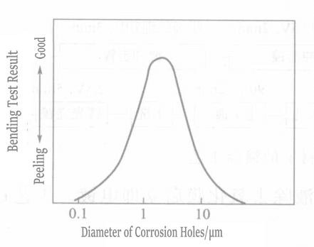
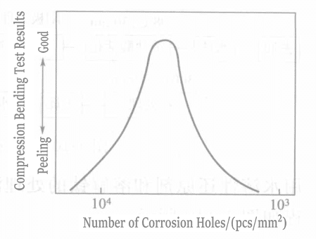
Liu and others used a method to generate micropores on the titanium surface, where controlling the micropores’ number, size, and depth is very important. The process is shown in Figure 1-111. The relationship between the size, number of micropores, and the bonding strength of the coating is shown in Figures 1-112 and 1-113.

Figure 1-111 Gold Plating Process of Titanium Material
Figure 1-112 Relationship Between Pitting Diameter and Bond Strength

Figure 1-112 Relationship Between Pitting Diameter and Bond Strength

Figure 1-113 Relationship Between Number of Pits and Bond Strength

Figure 1-113 Relationship Between Number of Pits and Bond Strength


(5) Summary

The key to obtaining good adhesion of the gold plating layer on titanium material is as follows:

① Quickly remove the oxide on the titanium surface and immediately electroplate before oxidation occurs.

② The fixation effect of micropores generated on the titanium surface improves the bonding strength.

③ Heat treatment methods remove sodium from the surface and gases in the coating.

コピーライト @ Sobling.Jewelry - ジュエリー カスタムジュエリーメーカー、OEMおよびODMジュエリー工場

ヘマンの写真
ヘマン

ジュエリー製品エキスパート --- 12年の豊富な経験

こんにちは、

私はヘマン、2人の素晴らしい子供の父親でありヒーローです。ジュエリー製品の専門家として、私のジュエリー経験を分かち合えることを嬉しく思います。2010年以来、HiphopblingやSilverplanetなど、世界中の29のクライアントにサービスを提供し、クリエイティブなジュエリーデザイン、ジュエリー製品開発、製造のサポートをしてきました。

宝石類プロダクトについての質問があったら、私に電話するか、または電子メールを送り、あなたのための適切な解決を論議し、職人の技量および宝石類の質の細部を点検するために自由な宝石類のサンプルを得ましょう自由に感じて下さい。

一緒に成長しよう!

コメントを残す

メールアドレスが公開されることはありません。 が付いている欄は必須項目です

投稿カテゴリー

ジュエリー制作のサポートが必要ですか?

ソブリングへのお問い合わせ
202407 heman - ジュエリー製品のエキスパート
ヘマン

ジュエリー製品のエキスパート

こんにちは、

私はヘマン、2人の素晴らしい子供の父親でありヒーローです。ジュエリー製品の専門家として、私のジュエリー経験を分かち合えることを嬉しく思います。2010年以来、HiphopblingやSilverplanetなど、世界中の29のクライアントにサービスを提供し、クリエイティブなジュエリーデザイン、ジュエリー製品開発、製造のサポートをしてきました。

宝石類プロダクトについての質問があったら、私に電話するか、または電子メールを送り、あなたのための適切な解決を論議し、職人の技量および宝石類の質の細部を点検するために自由な宝石類のサンプルを得ましょう自由に感じて下さい。

一緒に成長しよう!

フォローする

ソブリングを選ぶ理由

Sobling チームメンバー シルバージュエリー製造工場
認証

ソブリングは品質基準を尊重する

ソブリングは、TUV CNAS CTCなどの品質証明書に準拠しています。

最新の投稿

図6-1 電解研磨

ジュエリーを輝かせる方法:ジュエリー製造における電気めっきプロセス

このガイドでは、ジュエリーをピカピカに美しく仕上げる方法を教えてくれる。このガイドでは、ジュエリーに光沢のあるメタル・コートを施す前のクリーニングと修理について説明します。ジュエリーをおしゃれに見せるために、ゴールドやシルバー、その他の金属を加えるさまざまな方法について説明します。お店やデザイナー、オンライン販売者など、ジュエリーを作ったり売ったりしている人に最適です。ジュエリーを新しく美しく保つコツを学びましょう!

続きを読む "
9999ファインゴールド

ジュエリー製造に使用される純金素材の紹介

ゴールド・ジュエリーは、純度、強度、スタイルがすべてです。このガイドでは、現代のテクニックを使って、高純度で耐久性があり、軽量なゴールド作品を作る方法を紹介しています。魅力的で高品質なゴールドの作品を作りたいジュエリー関係者は必読です。

続きを読む "
ステップ13 「右のイヤリング・ペンダントの色」レイヤーを作成する。続けて右のタツノオトシゴ型のペンダントに色をつけます。ステップ 14 「パールカラー」レイヤーを作成します。パールのベースカラーとしてマゼンタを適用する。シャドウ/ハイライトを定義する。全体の明暗のコントラストとカラーバランスを調整して完成。

ジュエリーデザインのキー・スキルとは?素材、テクニック、ビジュアル・プレゼンテーション

このガイドは、ジュエリーショップ、スタジオ、ブランド、デザイナー、販売者に最適です。ダイヤモンド、真珠、翡翠、金属など、さまざまな素材を使ったジュエリーの描き方とデザイン方法が網羅されています。鉛筆、水彩絵の具、マーカー、タブレットを使ったスケッチ、着色、3Dビューの作成など、ステップ・バイ・ステップのテクニックを学ぶことができます。特注品や有名人のデザインに最適です。

続きを読む "
図5-21 金属エッジのプレス

宝石を完璧にセットする方法:ジュエリー製作者のためのステップ・バイ・ステップ・ガイド

この記事はジュエリー制作の愛好家にとって宝の山であり、宝石のセッティングの詳細なテクニックを提供している。宝石の準備から、ホットワックスで宝石を固定する方法まで、プロングやベゼルセッティングなど、具体的なセッティング方法を網羅している。また、一般的なツールの使い方やステップ・バイ・ステップの作業も掲載されており、ジュエリーショップ、スタジオ、ブランド、小売店、デザイナー、eコマースやドロップシッピングの販売者などが、ジュエリー製作のスキルを高めて、素晴らしいカスタム・ジュエリーを製作するのに役立つ。

続きを読む "
図8-9 金型の水爆発洗浄

ジュエリー鋳物のクリーニングと検査方法:鋳型の種類に応じたテクニック

ジュエリーの鋳造を完璧にする方法を学びましょう!このガイドは、ジュエリー・メーカー、ショップ、デザイナーが、石膏やワックスなど、さまざまな鋳型を使用する際に役立ちます。また、鋳造後のジュエリーのクリーニングや修理の方法も紹介しています。セレブ御用達のカスタム・ジュエリーを作る方にも、オンラインで販売する方にも、よくある問題を避け、ジュエリーを輝かせるヒントが得られます。

続きを読む "
銀メッキとは何か、どのように行われるのか、なぜ使用されるのか

銀メッキとは何か、どのように行われるのか、そしてなぜ使用されるのか?

ジュエリーの銀メッキについて学びましょう。このガイドでは、メッキ工程、溶液(シアン化物および非シアン化物)、光沢剤、そしてより密着性を高めるための前メッキについて解説します。銀銅や銀パラジウムといった銀合金、その特性、そして完璧な仕上がりを実現するためのよくあるメッキの問題解決方法も解説します。宝石職人やデザイナーにとって必携の資料です。

続きを読む "
ジェムストーン

14種類の宝石の秘密:カイヤナイト、コーディエライト、その他のガイド

あまり知られていないが魅力的な宝石の数々を探検しよう。サファイアのような色合いのカイヤナイトから、神秘的なスギライト、鮮やかな模様のマラカイトまで、それぞれの特徴をご紹介します。個性的な宝石を求めるジュエリー・デザイナーやコレクターに最適です。

続きを読む "
顔に似合うジュエリー

顔の形、体型、服のスタイルに合ったジュエリーを見つけるには?

このガイドは、顔の形、体型、服装にジュエリーを合わせるのに役立ちます。どのイヤリング、ネックレス、ブレスレットが様々なルックに最も似合うかを学ぶことができます。ジュエリー・ショップ、デザイナー、オンライン販売に最適です。どんなスタイルやシーンにもぴったりのジュエリーを見つけましょう。

続きを読む "

10%オフ

すべての一次オーダーについて

ニュースレターに参加する

最新情報をお届けします!

ソブリングジュエリーメーカー あなたのジュエリーのための見積もりを得る
究極のソーシング・ガイド - 新規サプライヤーからの調達を数百万ドル節約する10のヒント
無料ダウンロード

ビジネスソーシングの究極ガイド

新しいサプライヤーからの宝飾品調達に役立つ10のヒント
Soblingジュエリーメーカー あなたのジュエリーデザインのための無料のカスタマイズ

ジュエリー工場、ジュエリーカスタマイズ、モアッサナイトジュエリー工場、真鍮銅ジュエリー、半貴石ジュエリー、合成宝石ジュエリー、淡水パールジュエリー、スターリングシルバーCZジュエリー、半貴石宝石カスタマイズ、合成宝石ジュエリー