Átfogó útmutató a rézötvözet ékszerek és gyártási technológia
Rézötvözet ékszerek elsajátítása: Technika, anyagok és trendek: Technikák, anyagok és trendek
Bevezetés:
Ez a cikk a rézötvözetből készült ékszerek lenyűgöző világába és gyártási módszereibe merül el. Négy fő részre oszlik:
1. Áttekintés: Ismerje meg a réz történetét, tulajdonságait és az ékszerkészítésben betöltött szerepét. Az olyan rézötvözeteket, mint a sárgaréz, a bronz és a kupronikkel, sokoldalúságuk és szépségük miatt emeljük ki.
2. Tiszta réz és magas réztartalmú ötvözetek: Fedezze fel a tiszta réz különböző típusait, például az oxigénmentes rezet és a mikroötvözött rezet, és azt, hogyan használják őket az ékszerekben tartósságuk és egyedi színük miatt.
3. Rézötvözetek: Fedezze fel az olyan népszerű ötvözeteket, mint a sárgaréz (réz-cink), a bronz (réz-ón) és a cupronickel (réz-nikkel), amelyek mindegyike különböző színeket, korrózióállóságot és megmunkálhatóságot kínál a lenyűgöző darabok készítéséhez.
4. Termelési technikák: A kiváló minőségű, szemet gyönyörködtető ékszerek létrehozásához betekintést nyerhet az olyan fejlett módszerekbe, mint az elveszett viaszöntés, a bélyegzés és az elektroformálás, valamint az olyan felületkezelések, mint az aranyozás és a polírozás.

vörös réz gyógyító karperec
Tartalomjegyzék
I. szakasz Áttekintés
A réz és a rézötvözetek a gyártási folyamat alapján két fő kategóriába sorolhatók: feldolgozás és öntés. Minden olyan ötvözet, amelynek elnevezésében Z előtag szerepel, az öntési ötvözetek közé tartozik. Ezzel szemben a feldolgozott réz és rézötvözetek elnevezését Kínában hagyományosan négy kategóriába sorolják: lila, sárga, zöld és fehér. Ezek közül a lila rézötvözeteket feldolgozott formában szállítják. A T előtag a lila réz kódját jelenti. A sárga pinyin első H betűje a sárga rezet jelöli. Hasonlóképpen a Q a bronzot, a B a kupronikkel, az ezt követő kémiai elemszimbólumok és számok pedig a hozzáadott elemek névleges tömegszázalékát jelölik.
A réz és a rézötvözetek funkciójuk alapján két kategóriába sorolhatók: általános és speciális célúak. Az ékszerekhez használt rézötvözetek a speciális rézötvözetek egy típusába tartoznak, amelyeknek különleges követelményei vannak az árnyalat, a korrózióállóság, az öntési teljesítmény, a megmunkálási teljesítmény, a hegesztési teljesítmény és a színezési teljesítmény. Az ékszergyártásban használt fő réz és rézötvözetek közé tartozik a tiszta réz és a magas réztartalmú ötvözetek, az ónbronz, a sárgaréz, a cink-kupronikkel, az arany-réz ötvözetek utánzata és az ezüst-réz ötvözetek utánzata.
II. szakasz Tiszta réz és nagy réztartalmú ötvözetek
1. Tiszta Popper és tulajdonságai
A tiszta réz kémiai összetétel alapján több kategóriába sorolható: közönséges tiszta réz, oxigénmentes tiszta réz és mikroötvözött tiszta réz.
(1) közönséges tiszta réz
A közönséges tiszta réz tömegtartalma legalább 99,7%, nagyon kevés szennyeződéssel, és lilásvörös megjelenésű. Ezért lila réznek is nevezik. A közönséges tiszta réz fő fajtái a T1, T2 és T3. A GB/T 5231-2001 szabvány szerint a közönséges tiszta réz általánosan használt kémiai összetétele a 2-1. táblázatban látható.
2-1. táblázat A közönséges tiszta réz általános kémiai összetétele (minőségi frakció egység: %)
| Fokozat | Cu+Ag | P | Bi | Sb | Mint | Fe | Ni | Pb | Sn | S | Zn | O | A szennyeződések összege |
| Legalább | Legfeljebb | ||||||||||||
| T1 | 99. 95 | 0.001 | 0.001 | 0.002 | 0.002 | 0.005 | 0.002 | 0.003 | 0.002 | 0.005 | 0.005 | 0.02 | 0.05 |
| T2 | 99. 90 | - | 0.001 | 0.002 | 0.002 | 0.005 | - | 0.005 | - | 0.005 | - | - | 0.1 |
| T3 | 99. 70 | - | 0.002 | - | - | - | - | 0.01 | - | - | - | - | 0.3 |
| (Liu Ping, 2007; Wang Biwen, 2007; Tian Rongzhang és Wang Shitang, 2002; Nemzeti színesfém-szabványosítási műszaki bizottság, 2012) | |||||||||||||
2-2. táblázat A közönséges tiszta réz fizikai tulajdonságai
| Teljesítmény Név | Számérték | Teljesítmény Név | Számérték |
|---|---|---|---|
| Rács típusa | Arcközpontú köbös | Elektronikus konfiguráció | A2 2s2 2P6 3s2 3P6 3d10 4s1 |
| Atomtömeg | 63.54 | Ellenállás | 0. 016 73 Ω-m |
| Atomsugár | 0. 157nm | Hővezető képesség(273-373K) | 399W/(m - K) |
| Ionsugár | 0. 073nm | Az ellenállás hőmérsékleti együtthatója | 0. 003 93/℃ |
| Sűrűség | 8. 92g/cm3 | Mágneses szuszceptibilitás | -0. 86 X 10-3/kg |
| Olvadáspont | 1 083. 4℃ | Fajlagos hőkapacitás | 0.39X 10³J/(kg -℃) |
| Forráspont | 2 567℃ | Lineáris tágulási együttható | 17. 6X10⁻⁶/℃ |
| (Liu Ping, 2007; Wang Biwen, 2007; Tian Rongzhang és Wang Shitang, 2002; Nemzeti színesfém-szabványosítási műszaki bizottság, 2012) | |||
A réz egy viszonylag inaktív nehézfém, amely jó korrózióállósággal rendelkezik. Száraz levegőn, szobahőmérsékleten stabil, melegítéskor pedig fekete rézoxid keletkezhet belőle. Vörös rézoxid keletkezik, ha magas hőmérsékleten tovább kalcinálják. Hosszú ideig tartó nedves levegőn való elhelyezés után a réz felületén lassan zöldkristály (bázikus rézkarbonát) réteg képződik. A verdigris megakadályozhatja a fém további korrózióját; összetétele változó, salétromsavban és forró tömény kénsavban oldódik, sósavban enyhén oldódik, és lúgok által könnyen korrodálható. Az elektrokémiai (fémaktivitási sorozatban) a réz a hidrogén után következik, ezért nem tudja kiszorítani a hidrogént a híg savakból. A réz azonban lassan oldódhat a levegőben ezekben a híg savakban. A réz reagálhat a felmelegített tömény sósavval, és könnyen oldódik salétromsavban és oxidáló savakban, például forró tömény kénsavban. A réz reagálhat vas-kloriddal is. Az ékszeriparban a vas-klorid oldatot gyakran használják a réz maratására, hogy különböző dekoratív textúrákat és mintákat hozzanak létre.
A közönséges tiszta réz mechanikai tulajdonságai szorosan kapcsolódnak az állapotához, amint azt a 2-3. táblázat mutatja.
2-3. táblázat A közönséges tiszta réz mechanikai tulajdonságai különböző állapotokban
| Teljesítmény | Réz feldolgozása | Visszatérő réz | Rézöntés |
|---|---|---|---|
| Rugalmassági határérték/ MPa | 280 ~ 300 | 20 ~ 50 | - |
| Folyáspont / MPa | 340 ~ 350 | 50 ~ 70 | - |
| Szakítószilárdság/ MPa | 370 ~ 420 | 220 ~ 240 | 170 |
| Nyúlás mértéke / % | 4 ~ 6 | 45 ~ 50 | - |
| Zsugorodási arány/ % | 35 ~ 45 | 65 ~ 75 | - |
| Brinell-keménység / HB | 1 100 ~ 1 300 | 350 ~ 450 | 400 |
| Nyírószilárdság/ MPa | 210 | 150 | - |
| Ütésállóság/J-cm-2 | - | 16 ~ 18 | - |
| Nyomószilárdság / MPa | - | - | 1570 |
| Felborulási arány/ % | - | - | 65 |
| (Liu Ping, 2007; Wang Biwen, 2007; Tian Rongzhang és Wang Shitang, 2002; Nemzeti színesfém-szabványosítási műszaki bizottság, 2012) | |||
(2) Oxigénmentes tiszta réz
Az oxigénmentes tiszta réz olyan tiszta réz, amelynek oxigéntartalmát különböző finomítási módszerekkel jelentősen csökkentették. A GB/T5231 szerint az oxigénmentes rezet többféle fokozatra osztják: nulla, egy és két fokozatú oxigénmentes réz, a megfelelő réz- és oxigéntartalom a 2-4. táblázatban látható. Az oxigénmentes réz nem mutat hidrogén ridegséget, és nagy elektromos vezetőképességgel, jó feldolgozhatósággal, hegesztési, korrózióállósággal és alacsony hőmérsékleten való viselkedéssel rendelkezik. Az oxigénmentes rezet általában előnyben részesítik az arany- és ezüstötvözetből készült töltőanyag készítésekor, hogy csökkentsék a szennyeződéseket a kötésben.
2-4. táblázat Az oxigénmentes réz oxigéntartalmára vonatkozó követelmények
| Fokozatok | Kód: | Réz + ezüst ≥ | Oxigén≯ |
|---|---|---|---|
| 0. számú oxigénmentes réz | TU0 | 99. 99 | 0. 0005 |
| No. 1 oxigénmentes réz | 99. 97 | 0.002 | |
| Nr. 2 oxigénmentes réz | TU2 | 99. 95 | 0.003 |
| (Nemzeti színesfém-szabványosítási műszaki bizottság, 2012) | |||
(3) Mikroötvözött tiszta réz
A mikroötvözött tiszta réz olyan ötvözőelemeket használ, mint a króm, cirkónium, ezüst, alumínium, foszfor, kén és antimon, amelyek nyomokban hozzáadva hatékonyan javítják a tiszta réz teljesítményét. A mikroötvözött tiszta réz többféle minőségű, például TUAg0,06, TUAg0,05, TUAg0,08, TUAg0,1, TUAg0,2, TUAg0,3, TUA10,12, TUZr0,15, TAg0,15, TAg0,1-0,01, TP3, TP4, TTe0,3, TTe0,5-0,008, TTe0,5-0,02, TZr0,15 stb. A cirkónium mikroötvözött tiszta réz példájaként a 2-5. táblázat mutatja a mechanikai tulajdonságait, amelyek jelentősen javultak a közönséges tiszta rézhez képest, és a lágyulási hőmérséklet elérte az 500 ℃-ot.
2-5. táblázat Cirkónium - mikroötvözött tiszta réz QZr0,2 mechanikai tulajdonságai
| Anyagi állapot | Szakítószilárdság/MPa | Folyáshatár/MPa | Nyújtási sebesség/% | Vickers-keménység/HV | Rugalmassági modulus/GPa |
|---|---|---|---|---|---|
| 980 ℃-on oltott, 500 ℃-on 1 órán keresztül érlelt | 260 | 134 | 19. 0 | 83 | - |
| 900 ℃ oltás, 500 ℃ öregedés 1 óra | 230 | 160 | 40. 0 | - | - |
| 900C fűtés 30 perc oltás, hideg megmunkálás 90% | 450 | 385 | 3.0 | 137 | 136 |
| 980 ℃ fűtés 1 óra, 90% hidegmegmunkálás, 400 ℃ öregedés 1 óra | 492 | 428 | 10.0 | 150 | 133 |
| 900 ℃ oltás, hideg megmunkálás 90%, 400 ℃ öregedés 1 óra | 470 | 430 | 10.0 | 140 | |
| (Liu Ping, 2007; Wang, B., 2007; Tian, R. Z. és Wang, S. T., 2002; National Technical Committee for Standardization of Nonferrous Metals, 2012) | |||||
2. Magas rézötvözet
A magas rézötvözetek, más néven alacsony ötvözetű réz, olyan rézötvözetekre utalnak, amelyek egy vagy több nyomelemet tartalmaznak bizonyos különleges tulajdonságok elérése érdekében. A réztartalom 99,3%~96%, és a feldolgozott termékek esetében nem sorolható be semmilyen rézötvözetcsoportba. Az öntött termékek esetében a réz tartalomnak nagyobbnak kell lennie, mint 94%, amelyet bizonyos tulajdonságok elérése érdekében hozzá lehet adni.
A szilárd oldatos szilárdítás és a csapadékos szilárdítás a rézötvözetek fontos szilárdítási módszerei. A leggyakoribb ötvözőelemek közé tartozik a Cr, Zr, Ti, Si, Mg, Te stb. Oldhatóságuk a rézben a hőmérséklet csökkenésével meredeken csökken. Ezek az elemek szilárd állapotban tiszta anyagként vagy fémvegyületekként csapódnak ki, ami szilárd oldat erősítést és csapadékos erősítést eredményez. Az amerikai öntöde magas rézötvözetű fajtái közé tartozik a C81300~C19600 és a feldolgozott magas rézötvözetű fajták a C16200-tól a C19600-ig terjednek. Az újonnan felülvizsgált GB/T5231-2012 "A feldolgozott réz és rézötvözetek fokozatai és kémiai összetétele" című kiadványban Kína olyan magas rézötvözetű minőségeket sorol fel, mint a TTi3,0 - 0,2, TNi2,4 - 0,6 - 0,5, TPb1,0, TC r1 - 0,18, TCr0,3 - 0,3, TCr0,5 - 0,1, TCr0,7, TCr0,8, TCr1 - 0,15.
3. A tiszta réz és a nagy réztartalmú ötvözetek technológiai teljesítménye
(1) Olvasztási folyamat
A tiszta réz és a nagy réztartalmú ötvözetek hajlamosak hidrogént és oxigént felvenni az öntési folyamat során, ami porozitáshoz és oxidációs zárványokhoz vezet, és befolyásolja az öntvények felületi minőségét. A hidrogén- és oxigéntartalom szorosan összefügg az anyag hőmérsékletével. A 2-6. táblázat mutatja a réz hidrogénoldhatóságát különböző hőmérsékleteken.
2-6. táblázat A hidrogén oldhatósága rézben 0,1 MPa nyomáson (Nie Xiaowu, 2006)
| Hőmérséklet /℃ | 400 | 500 | 600 | 700 | 800 | 900 | 1000 | 1100 | 1200 | 1300 | 1400 | 1500 |
|---|---|---|---|---|---|---|---|---|---|---|---|---|
| Oldhatóság /cm3 - (100g réz)-1 | 0.06 | 0.16 | 0. 3 | 0.49 | 0. 72 | 1.08 | 1.58 | 6.3 | 8. 1 | 10.9 | 11.8 | 13.6 |
Az oxigén nem oldódik a rézben, és magas olvadáspontú, törékeny vegyületeket képez Cu2O rézzel. Amikor az oxigéntartalmú réz kondenzálódik, az oxigén eutektikumként (Cu+Cu2O), amely a szemcsehatárok mentén oszlik el. Az eutektikus hőmérséklet nagyon magas (1066 ℃ )és nem befolyásolja a hődeformációs teljesítményt, de kemény és rideg, ami megnehezíti a hidegdeformációt és a fém "hideg ridegségéhez" vezet. Ha az oxigéntartalmú rezet hidrogén- vagy redukáló atmoszférában izzítják, "hidrogén ridegség" lép fel. A "hidrogén ridegség" lényege, hogy a lágyítás során a hidrogén vagy a redukáló atmoszféra könnyen behatol a rézbe, és a CuO oxigénnel reagálva vízgőzt vagy CO2. Ezért az olvasztás során egyértelmű technológiai előírásokat kell megállapítani és végrehajtani.
A tiszta réz olvasztható tükrös vagy magindukciós elektromos kemencével. A reflexiós kemencében történő olvasztás során vas- vagy rézöntőformák felhasználásával finomítási eljárásokkal sűrű ingot lehet nyerni az öntéshez, és a tartókemencében félig folyamatos vagy folyamatos öntés is végezhető. Az indukciós olvasztási folyamatra a következő folyamatfolyamatra lehet hivatkozni.
① Először melegítse elő a tégelyt sötétvörös színűre, majd adjon hozzá egy réteg száraz szenet vagy fedőanyagot ( 63% bórax + 37% zúzott üveg) körülbelül 30 ~ 50 cm vastagságban a tégely alján, majd a sarokmaradékok, hulladéktömbök és rudak anyagai, végül pedig tiszta réz hozzáadása.
② A hozzáadott ötvözőelemeket a kemence platformján lehet előmelegíteni, és szigorúan tilos hideg anyagokat hozzáadni az olvadt fémhez. A töltetet a teljes olvadási folyamat alatt gyakran kell keverni a hídképződés megakadályozása érdekében.
③ Miután az ötvözet teljesen megolvadt a fűtés miatt, amikor a hőmérséklet eléri az 1200 ~ 1250 ℃-ot, adjunk hozzá foszforréz dezoxidálót, amely az olvadt ötvözet tömegének 0,3% ~ 0,4%-jét teszi ki. A foszfor a következőképpen reagál a rézoxiddal:
5Cu2O + 2P = P2O5 + 10Cu
Cu2O + P2O5 = 2CuPO3
A keletkező gáz P2O5 kiszabadul az ötvözetből, és a rézfoszfát a felszínen lebeghet, lehetővé téve a salak eltávolítását a dezoxidáció céljának elérése érdekében. Ezenkívül a dezoxidációs folyamat során folyamatos keverésre van szükség.
④ Végül a salakot eltávolítjuk, és az ötvözött folyadék öntési hőmérséklete általában 1150 ℃ ~ 1230 ℃.
(2) Feldolgozási technológia
A tiszta réz és a magas rézötvözetek kiváló hideg- és melegmegmunkálási tulajdonságokkal rendelkeznek. Megmunkálásuk hagyományos préselési technikákkal, például nyújtással, hengerléssel, mélyhúzással, hajlítással, precíziós préseléssel és fonással végezhető. A 2-2. ábra egy példa egy préselt tiszta réz ékszer-nyersanyagra. Meleg feldolgozás során a fűtőközeg atmoszféráját 380~650 ℃-ra kell szabályozni. A 800 ~ 900 ℃ lágyítási hőmérsékletet lehet választani a szokásos tiszta rézfeldolgozáshoz, a 360 ℃ forró üzemi hőmérsékletet lehet választani, és a tipikus lágyulási hőmérséklet körülbelül. A magas rézötvözet esetében a lágyulási hőmérséklet nagyobb kapcsolatban van a kémiai összetételével, mint például a Cr és Zr ötvözetű magas rézötvözet (Cr0,25-0,65, Zr0,08-0,20), és a lágyulási hőmérséklete elérheti az 550 ℃-ot. A hegesztésben a tiszta réz és a magas rézötvözetek könnyen használhatóak ónhegesztéshez és forrasztáshoz, gázvédett ívhegesztéshez, villámhegesztéshez, elektronsugaras hegesztéshez és gázhegesztéshez.
2-3. ábra Réz elektróda ékszerformák bélyegzéséhez
2-4. ábra Maratási eljárással előállított tiszta réz ékszerek
III. szakasz Rézötvözetek
A tiszta réz gyenge mechanikai és öntési tulajdonságai miatt a népszerű ékszerekhez használt rézanyagok többsége rézötvözet. A rézötvözeteknek számos kategóriája létezik, és jelenleg nincsenek konkrét műszaki szabványok az ékszerekben használt rézötvözetekre vonatkozóan, sem hazai, sem nemzetközi szinten. Jellemzően ipari rézötvözet minőségeket használnak, és az alkalmazás meglehetősen kaotikus, ami befolyásolja a termék minőségét. Ezért az ékszerekhez használt rézötvözetek további szabványosításra szorulnak. Az ékszeripari rézötvözetek nem teljesen azonosak az ipari rézötvözetekkel, és egyedi követelményekkel rendelkeznek.
(1) Az ötvözetnek meg kell felelnie az ékszerekre vonatkozó felhasználási követelményeknek. Bizonyos mechanikai tulajdonságokkal kell rendelkeznie, meg kell felelnie a beállítási követelményeknek, jó korrózióállósággal kell rendelkeznie, nem szabad hajlamosnak lennie a feszültségkorróziós repedésre, és bizonyos színekkel kell rendelkeznie stb.
(2) Az ötvözetnek meg kell felelnie a különböző technológiai követelményeknektöbbek között: ① Jó öntési teljesítmény. A rézötvözetnek jó folyékonysággal és minimális megszilárdulási zsugorodással kell rendelkeznie, amikor a díszek gyártása során az elveszett viaszöntési eljárást alkalmazzák. ② Hegesztési teljesítmény. A hegesztés során ne keletkezzenek könnyen repedések, oxidáció, gázelnyelés és színkülönbségek. ③ Megmunkálhatóság. A keménységnek mérsékeltnek kell lennie; ha túl magas, a szerszámkopás jelentős lesz, és ha túl alacsony, nehéz lesz nagy felületi fényességet elérni. ④ Felületkezelési teljesítmény. A legtöbb rézdíszmű felületkezelést igényel, amelynek jó színminőséggel kell megkönnyítenie a színezést és a korróziógátló kezelést.
Az ékszerekhez használt rézötvözetek között többféle típus is megtalálható, mint például a sárgaréz, a cupronickel és a bronz.
1. Sárgaréz
1.1 A sárgaréz típusai
A sárgaréz összetétele két fő kategóriába sorolható: egyszerű sárgaréz és különleges sárgaréz.
(1) Egyszerű sárgaréz
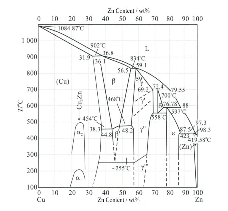
Az egyszerű sárgaréz egy rézből és cinkből álló bináris ötvözet, ahol a cink szerepe a sárgarézben elsősorban a szilárdság növelése, a szín beállítása és az öntési teljesítmény javítása. A bináris sárgaréznek három közös egyensúlyi mikroszerkezete van (2-5. ábra): ha a cinktartalom kisebb, mint 38%, akkor egyfázisú α; ha a cinktartalom 38%~47%, akkor α+β; ha a cinktartalom 47%~50%, akkor egyfázisú β, és kis sárgaréznek, α+β sárgaréznek és β sárgaréznek nevezik. Ha a cinktartalom meghaladja a 39%-t, az ötvözet kemény és rideg lesz, ami befolyásolja az alkalmazási értékét. Ezért az ékszerekhez használt közönséges sárgaréz réztartalma általában meghaladja a 60% értéket.
2-7. táblázat Gyakori sárgarézfajták és kémiai összetételük
| Sorszám | Osztályszám | Kémiai összetétel/% | |||||
|---|---|---|---|---|---|---|---|
| Cu | Fe | Pd | Ni | Zn | Összes szennyeződés | ||
| 95.0 ~ 97. 5 | 0.10 | 0.03 | 0.5 | Margin | 0.2 | ||
| 2 | H90 | 88. 0 ~ 91.0 | 0.10 | 0.03 | 0.5 | Margin | 0.2 |
| 3 | H85 | 84. 0 ~ 86. 0 | 0.10 | 0.03 | 0.5 | Margin | 0.3 |
| 4 | H80 | 79. 0 ~ 81.0 | 0.10 | 0.03 | 0.5 | Margin | 0.3 |
| 5 | H70 | 68. 5 ~ 71. 5 | 0.10 | 0.03 | 0.5 | Margin | 0.3 |
| 6 | H68 | 67.0 ~ 70.0 | 0.10 | 0.03 | 0.5 | Margin | 0.3 |
| 7 | H65 | 63. 5 ~ 68. 0 | 0.10 | 0.03 | 0.5 | Margin | 0.3 |
| 8 | H63 | 62.0 ~ 65.0 | 0.15 | 0.08 | 0.5 | Margin | 0.5 |
| 9 | H62 | 60. 5 ~ 63. 5 | 0.15 | 0.08 | 0.5 | Margin | 0.5 |
| 10 | H59 | 57. 0 ~ 60. 0 | 0.30 | 0.5 | 0.5 | Margin | 1.0 |
| (Liu Ping, 2007; Wang Biwen, 2007; Tian Rongzhang és Wang Shitang, 2002; Nemzeti színesfém-szabványosítási műszaki bizottság, 2012) | |||||||
2-8. táblázat A közönséges sárgaréz felületi színei
| Fokozatok | Réz tartalom /wt% | Cink tartalom /wt% | Színes |
|---|---|---|---|
| H59 | 59 ~ 63 | Margin | Világosbarna - arany színű |
| H65 | 63 ~ 68. 5 | Margin | Tiszta sárga |
| H68,H70 | 68. 5 ~ 71. 5 | Margin | Zöld - Arany |
| H80 | 78. 5 ~ 81. 5 | Margin | Arany szín egy csipetnyi vörössel |
| H85 | 84 ~ 86 | Margin | barnássárga - aranyszínű |
| H90 | 89 ~ 91 | Margin | Antik bronz - arany szín |
| H96 | 94 ~ 96 | Margin | Vöröses-barna |

A cinknek a réznél sokkal alacsonyabb elektródpotenciálja miatt az ötvözetek semleges sóoldatokban hajlamosak az elektrokémiai korrózióra. Az alacsonyabb potenciálú cink feloldódik, míg a réz porózus filmként marad a felületen, mikroelemeket képezve a felület alatt lévő sárgaréz-összetétellel, ami a sárgaréz anódként viselkedik, és felgyorsítja a korróziót. Ezért a sárgaréz ékszerek általában felületvédelmi kezelést igényelnek, például nemesfémréteggel történő galvanizálással vagy védőbevonat felhordásával.
(2) Különleges sárgaréz
Az egyszerű sárgaréz teljesítményének javítása érdekében 1%~5% elemeket, például ónt, ólmot, alumíniumot, szilíciumot, vasat, mangánt és nikkelt adnak az ötvözethez, így terner, quaterner vagy akár quaterner ötvözeteket alkotnak, amelyeket speciális sárgaréznek vagy komplex sárgaréznek neveznek, és a sárgaréz nevéhez a hozzáadott elemeket előtaggal jelölik, például ón sárgaréz, ólom sárgaréz, alumínium sárgaréz, mangán sárgaréz, alumínium-mangán sárgaréz stb. Az ón gátolhatja a dezinkciós korróziót és fokozhatja a sárgaréz korrózióállóságát. Az ólom nagyon alacsony oldékonyságú a sárgarézben, és szabad részecskék formájában oszlik el a mátrixban, ami a forgácsok törését okozhatja és kenést biztosíthat, ezáltal javítja az anyag megmunkálhatóságát és kopásállóságát. Az alumínium szilárd oldatot erősítő szerepet játszik, a felületen védő alumínium-oxid filmet képezve. A szilícium sárgaréz magas korrózióállósággal, mechanikai és öntési tulajdonságokkal, valamint erős feszültségkorrózióállósággal rendelkezik. A nikkel sárgaréz nagy szilárdsággal, szívóssággal és korrózióállósággal rendelkezik, és ellenáll a hideg és forró műanyag feldolgozásnak.
A sárgaréz komplex szerkezete a sárgarézhez hozzáadott elemek "cinkegyenérték-koefficiens" alapján becsülhető. A réz-cink ötvözethez kis mennyiségű más ötvözőelem hozzáadása általában csak az α/(α+β) fázistérséget tolja el a Cu-Zn állapotdiagramban balra vagy jobbra. Például 1% ónegyenérték hozzáadása a 2% cink szerkezeti tulajdonságokra gyakorolt hatásához azt jelenti, hogy az ón cinkegyenértéke 2. A különböző ötvözőelemek cinkegyenértékeit a 2-9. táblázat mutatja.
2-9. táblázat Különböző ötvözőelemek cinkegyenértékei
| Ötvözet elemek | Szilícium | Alumínium | Tin | Lead | Vas | Mangán | Nikkel |
|---|---|---|---|---|---|---|---|
| Cink egyenérték | + 10 | + 6 | + 2 | + 1 | + 0. 9 | + 0. 5 | -1. 3 |
Ezért a különleges sárgaréz szerkezete általában megfelel a közönséges sárgaréz szerkezetének, megnövelt vagy csökkentett cinktartalommal. A komplex sárgaréz α és β fázisa többkomponensű komplex szilárd oldatok, amelyek nagyobb erősítő hatással rendelkeznek. Ezzel szemben a közönséges sárgarézben az α és β fázis egyszerű szilárd Cu-Zn oldatok, kisebb erősítő hatással. Bár a cink-egyenértékek összehasonlíthatóak, a többszörös szilárd oldat tulajdonságai különböznek az egyszerű bináris szilárd oldatétól. Ezért egy kis mennyiségű többszörös szilárdítással javítható az ötvözet teljesítménye.
A különleges sárgarézben egy rézalapú aranyutánzatot "ritka arany" néven ismerik, amelyet széles körben használnak ékszerekben és kézműves termékekben. Köztudott, hogy az arany ragyogó aranyszínnel, jó kémiai stabilitással rendelkezik, melegítéskor nem változtatja meg a színét, és kiváló oxidációállósággal rendelkezik, így régóta kedvelt választás a művészeti dísztárgyakhoz. Magas ára miatt azonban a hasonló tulajdonságokkal rendelkező, olcsó ötvözeteket széles körben használják helyettesítő anyagként. Az elmúlt években a kutatók mind hazai, mind nemzetközi szinten versenyeztek az aranyat helyettesítő rézalapú aranyutánzó ötvözetek kifejlesztéséért, és jelentős előrelépést értek el. Ezeknek az anyagoknak az arany színe vetekedhet a 16K~22K arannyal, és jó korrózióállósággal és megmunkálhatósággal rendelkeznek.
A ritkafém-réz alapú aranyutánzat ötvözetekben általában cinket, alumíniumot, szilíciumot és ritkaföldfémeket használnak ötvözőelemként, és az egyes elemek hatása a színre és az oxidációs ellenállásra a következő.
① Cink. A Zn a rezet vörösről sárgára változtathatja, a fő elem aranysárga csillogást képez. A Zn javíthatja az ötvözetek elszíneződéssel szembeni ellenállását, és a Zn-tartalom növekedésével az elszíneződéssel szembeni ellenállás javul.
② Alumínium. Az Al egy másik fontos elem, amely hozzájárul az ötvözetek színéhez. Az alumíniumtartalom jelentősen befolyásolja az ötvözet színét; az alumíniumtartalom növekedésével az ötvözet által visszavert fény fő hullámhossza csökken, és az árnyalat vörösről sárgára változik. Az alumíniumtartalom további növelése észrevehetően gyengíti az ötvözet sárga árnyalatát, ami nagyobb színkülönbséget eredményez az ötvözet és a tiszta arany között. Az ötvözet szerkezete egyenletesebbé válik, ha alumíniumot adnak a sárgarézötvözetekhez. Elősegíti a β fázis kialakulását, ami segít csökkenteni a sárgarézben a dezinkciós korróziót, és javítja az aranyszerű ötvözetek elszíneződésgátló teljesítményét a mesterséges izzadásban. Ennek oka az, hogy ha az alumíniumtartalom kellően magas, akkor az ötvözet felületén sűrű és szilárdan rögzült, rézből és alumíniumból álló vegyes oxid védőfilm alakul ki, és ez a film sérülés esetén öngyógyító képességgel rendelkezik. Az elszíneződésgátló teljesítmény gyenge, ha az alumíniumtartalom túl alacsony ahhoz, hogy sűrű védőfilmet képezzen.
③ Szilícium. A Si javíthatja az ötvözetek színének és elszíneződésének ellenállását. Ha 0,05% ~ 2,50% Si-t adunk az ötvözethez, a Si nélküli azonos ötvözethez képest az elszíneződéssel szembeni ellenállási idő a mesterséges izzadságban 50% ~ 100%; ugyanazon a fűtési hőmérsékleten az elszíneződéssel szembeni ellenállási idő 50% növekszik. A Si hozzáadása javíthatja az ötvözet folyékonyságát és kopásállóságát is.
④ Ritkaföldfémek. A ritkaföldfémek hozzáadása a sárgaréz ötvözetekhez fokozhatja az ötvözet fényességét, javíthatja annak színét, valamint jó kopásállóságot, keménységet és az aranyhoz hasonló színt biztosíthat, amely nem fakul ki könnyen. Az ékszeriparban általában "ritka arany anyagként" emlegetik. A ritka arany anyagból készült ékszerek színe hasonlíthat a 18K vagy 20K aranyéhoz, nem oxidálódik vagy fakul ki könnyen, így alkalmas a mindennapi viseletre, és olcsó, így a magasabb minőségű arany utánzatú ékszerek előállításának anyagává válik.
A 2-10. táblázat számos gyakori arany-réz utánzatú ötvözetet mutat be, amelyek a rézalapú Cu-Al rendszerű és a Cu-Zn rendszerű ötvözetek közé sorolhatók.
2-10. táblázat Több aranyréz-utánzat kémiai összetétele (minőségi frakció egység: %)
| Fokozatok száma | Alumínium | Tin | Nikkel | Szilícium | Cink | Mangán | Ritkaföldfémek | Réz | Megjegyzések |
|---|---|---|---|---|---|---|---|---|---|
| Cu - 12. 5Zn - 1Sn | 1.0 | 12. 5 | A többi | Vöröses-arany | |||||
| Cu - 22Zn - 2Sn - 1P | 2.0 | 22.0 | Foszfor 1.0 | A többi | Világos aranysárga | ||||
| Cu - 35Zn - 1. 5Sn | 1.5 | 30.0 ~ 40.0 | A többi | Aranysárga | |||||
| Cu - 6Al - 15Zn - 0. 5Si | 6 | 0. 5 | 15 | A többi | |||||
| Sub - arany | 5.6 | 0. 26 | 0.70 | 92.6 | Megvizsgált összetétel | ||||
| Sub - arany | 0.38 | 0.03 | 48.74 | 50.64 | Megvizsgált összetétel | ||||
| Ritkaföldfém arany | 5 ~ 6 | 1 ~ 3 | 25 ~ 32 | 0. 8 ~ 1.5 | 0.1 | A többi | 18K arany szín | ||
| Ritkaföldfém arany | 2 ~ 10 | 1 ~ 1.5 | 0. 05 ~ 2. 5 | 5 ~ 30 | 0. 05 ~ 0. 50 | A többi | 18K arany szín | ||
| (Wang Biwen et al., 1998) | |||||||||
1.2 A sárgaréz tulajdonságai
(1) Korrózióállósági teljesítmény
A sárgaréz rosszul ellenáll a korróziónak magas hőmérsékleten, magas páratartalomban és sós ködben, és "dezinkciós korrózió" is előfordulhat áramló forró tengervízben (a cink először feloldódik, és porózus, szivacsszerű tiszta rezet hagy a munkadarab felületén). Nedves légkörben, különösen az ammóniát és SO2 , a sárgaréz feszültségkorróziós repedéseken megy keresztül. Az újonnan polírozott sárgaréz dísztárgyak felülete tompa lesz, vagy bizonyos területeken sötét foltok alakulnak ki, még akkor is, ha egy ideig levegőnek van kitéve. Ezért a sárgaréz dísztárgyak általában felületfestést vagy galvanizáló kezelést igényelnek a korrózióállóságuk javítása érdekében.
(2) Öntési folyamat teljesítménye
A sárgaréz megszilárdulási tartománya nagyon kicsi, így a folyékony fém folyékonysága jó, a töltési képesség kiváló, és a zsugorodási üregek tendenciája alacsony. Az olvadás során a cink nagy gőznyomást hoz létre, hatékonyan távolítja el a gázokat a rézfolyadékból, így a sárgarézben nehezen alakulnak ki pórusok. Az olvadási hőmérséklet alacsonyabb, mint az ónbronzé, és az öntés viszonylag kényelmes, ami lehetővé teszi a kis ékszerdarabok egyszerű öntését. Rézből készült kézműves termékek öntésére is gyakran használják.
(3) Mechanikai tulajdonságok
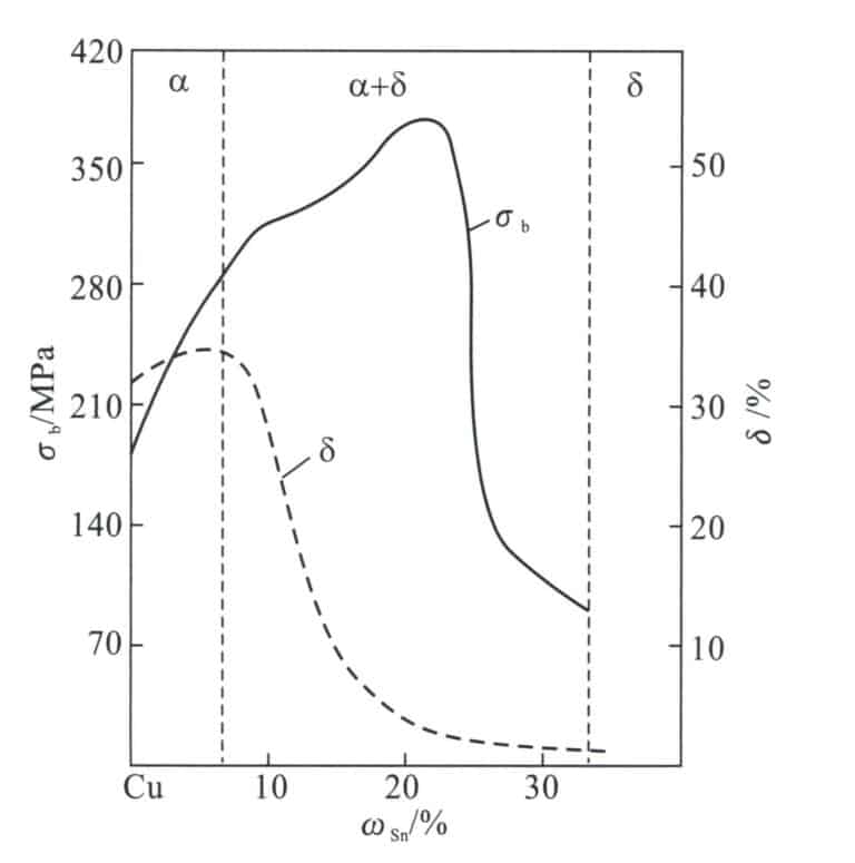
A sárgaréz eltérő cinktartalma miatt a mechanikai tulajdonságok is eltérőek. Az α sárgaréz esetében a cinktartalom növekedésével mind a σb, mind a δ folyamatosan emelkedik. Az (α+β) sárgaréz esetében a szobahőmérsékleten mért szilárdság folyamatosan javul, amikor a cinktartalom körülbelül 45%-re nő. Ha a cinktartalmat tovább növeljük, a szilárdság meredeken csökken a ridegebb γ fázis megjelenése miatt (egy szilárd oldat, amely Cu5 Zn8 ) az ötvözet szerkezetében. A szobahőmérsékleten a cink tartalom képlékenysége. Másrészt az (α+β) sárgaréz következetesen csökken a cink tartalom növekedésével. Ezért a 45%-nél nagyobb cink-tartalmú réz-cink ötvözeteknek nincs gyakorlati értéke.
(4) Megmunkálhatóság
Az egyfázisú α sárgaréz (H96-tól H65-ig) jó képlékenységgel rendelkezik, és ellenáll a hideg és meleg feldolgozásnak. Az egyfázisú α sárgaréz azonban hajlamos a középhőmérsékletű ridegségre a forró feldolgozás során, mint például a kovácsolás, a Zn-tartalomtól függően változó, általában 200 ~ 700 ℃ közötti hőmérséklet-tartományban. Ezért a hőmérsékletnek a meleg feldolgozás során 700 ℃ felett kell lennie. Az egyfázisú α sárgarézben a középhőmérsékletű ridegség zóna fő oka a két rendezett Cu3 Zn és Cu9 Zn az ötvözet Cu-Zn rendszerének rendezett α fázisú régiójában, amelyek közepes és alacsony hőmérsékletű hevítés során rendezett átalakuláson mennek keresztül, ami az ötvözetet rideggé teszi; emellett az ólom és a bizmut káros szennyeződések nyomokban alacsony olvadáspontú eutektikus filmeket képeznek, amelyek a rézzel a szemcsehatárokon oszlanak el, és a forró feldolgozás során intergranuláris repedést okoznak. A gyakorlat azt mutatja, hogy a nyomnyi mennyiségű cérium hozzáadásával a középhőmérsékletű ridegség hatékonyan kiküszöbölhető.
A kétfázisú sárgaréz (H63-tól H59-ig) ötvözetszerkezetében a képlékeny α fázis mellett egy szilárd oldat β is található, amely a CuZn elektronikus vegyületen alapul. Ez a fázis magas hőmérsékleten nagy képlékenységű, míg a β' fázis (rendezett szilárd oldat) alacsony hőmérsékleten kemény és rideg. Ezért az (α+β)sárgarézeket forró állapotban kell kovácsolni. A 46%~50%-nél nagyobb cinktartalmú β sárgaréz tulajdonságai miatt kemény és rideg, és nem lehet nyomáson megmunkálni.
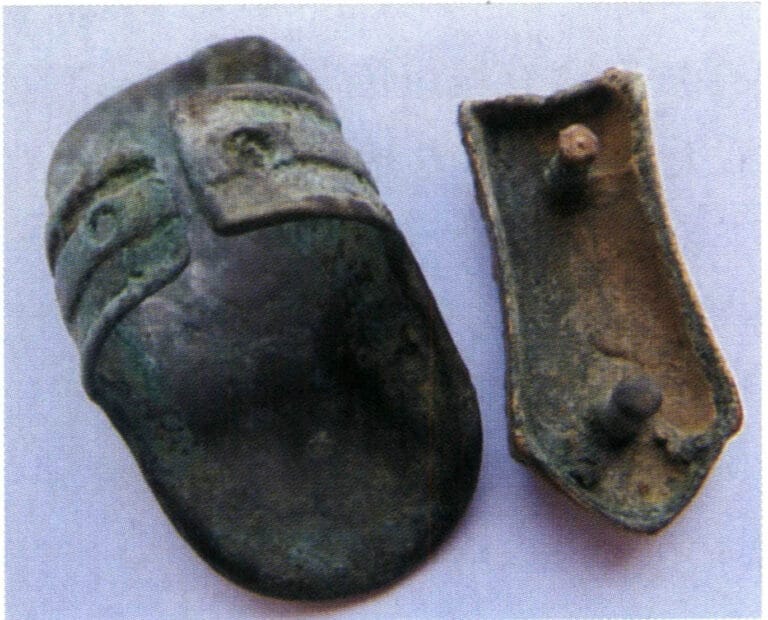
A viszonylag finom ékszerek esetében a sárgaréz általában hideg megmunkálással készül. A sárgaréz anyagok, például huzal, lemez és lemez anyagok felhasználhatók a végtermék hidegfeldolgozással történő előállításához. Természetesen a feldolgozás során közbenső lágyítást alkalmaznak a sárgaréz plaszticitásának helyreállítására és a munkakeményedés miatti repedések megelőzésére. A 2-7. ábra egy sárgarézből készült karabiner csatot, a 2-8. ábra pedig egy sárgarézből készült karkötőt mutat. A sárgarézlemezek gravírozásra is felhasználhatók, különböző kézi technikákat alkalmazva, mint például a tolás, fúrás, szedés, csavarás és húzás, hogy képeket véssenek a rézlemez felületére. A bevésett képeket ezután 24K-s arany védőréteggel galvanizálják, így jön létre az "arany szoborfestés".
(5) Hegesztési teljesítmény
A sárgaréz hegesztési teljesítménye jó. Nagyobb kézműves munkákhoz általában gázhegesztést használnak; finom ékszerekhez általában fáklyás hegesztést alkalmaznak.
(6) Polírozási teljesítmény
A sárgaréz vágási teljesítménye jó, és ellenáll az olyan műveleteknek, mint a korrekció, a polírozás és a befejezés. Az ékszereket a hagyományos ékszerkészítési módszerekkel nagyon fényesre lehet polírozni.
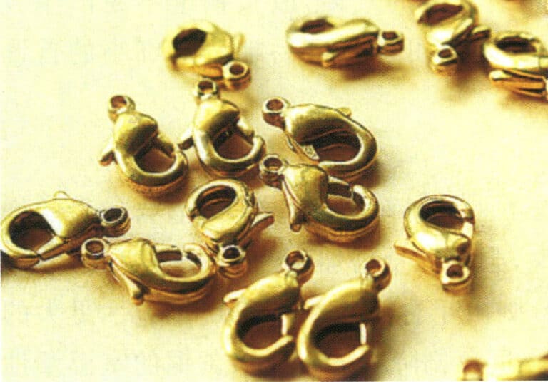
2-7. ábra Sárgaréz feldolgozott homárkapocs
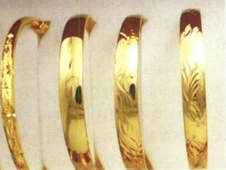
2-8. ábra Sárgaréz karkötő
2. Kupronikkel
2.1 A cupronikkel típusai
A kupronikkel három kategóriába sorolható: közönséges kupronikkel, komplex kupronikkel és ipari kupronikkel.
(1) Rendes kupronikkel
A réz-nikkel bináris ötvözetet közönséges kupronikkelnek nevezik, amelyet általában B betűvel jelölnek, a következő számmal, amely a réztartalmat jelzi, például B30, amely a Ni 30%-t tartalmazó réz-nikkel ötvözetet jelzi. A modellek közé tartozik a B0,6, B19, B25, B30 stb.
(2) Komplex kupronikkel
Az olyan összetett sárgarézötvözetet, amely olyan elemeket tartalmaz, mint a mangán, vas, cink és alumínium, összetett sárgaréznek nevezik, amelyet a B betűvel jelölnek, az ötvözet elemei pedig, mint például a BMn3-12, a Ni3% és Mn12%-t tartalmazó réz-nikkel-mangán ötvözetet jelölik. A komplex sárgaréznek négy típusa létezik.
- Ferro-kupronikkel. A modellek a következők: BFe5-1,5-1(Fe)-0,5(Mn), BFe10-1(Fe)-1(Mn), BFe30-1(Fe)-1(Mn). A ferro-kupronikkelhez hozzáadott vas mennyisége nem haladja meg a 2%-t a korróziós repedés megelőzése érdekében, és jellemzői közé tartozik a nagy szilárdság és a jelentősen javuló korrózióállóság, különösen az áramló tengervíz korróziójával szemben.
- Mangán-kupronnikkel. A modellek a következők: BMn3-12, BMn40-1,5, BMn43-0,5. A mangán-kupronikkel alacsony hőmérsékleti ellenállási együtthatóval rendelkezik, széles hőmérséklet-tartományban használható, jó korrózióállósággal és jó megmunkálhatósággal rendelkezik.
- Cink-kupronikkel. A modellek a következők: BZn18-18, BZn18-26, BZn18-18, BZn15-12 (Zn) - 1,8(Pb), BZn15-24(Zn)-1,5(Pb). A cink-kupronikkel kiváló átfogó mechanikai tulajdonságokkal, kiváló korrózióállósággal, jó hideg és meleg feldolgozási alakíthatósággal rendelkezik, könnyen vágható, és drót, rúd és lemez anyagok készíthetők, amelyeket precíziós alkatrészek gyártására használnak olyan területeken, mint a műszerek, mérőműszerek, orvosi eszközök, napi szükségletek és kommunikáció.
- Alumínium-kupronikkel. A modellek közé tartozik a BAl13-3 és a BAl16-1.5. Az ólombronz egy réz-nikkel ötvözethez alumínium hozzáadásával képzett ötvözet. Az ötvözet tulajdonságai az ötvözet nikkel- és alumíniumtartalmának arányától függenek, a legjobb tulajdonságok akkor jelentkeznek, ha Ni:Al=10:1. A leggyakrabban használt alumínium-kupronikkel ötvözetek a Cu6Ni1,5Al, Cu13Ni3Al, amelyeket főként a hajóépítésben, az elektromos energiában, a vegyiparban és a nagy szilárdságú korrózióálló alkatrészekben használnak ezekben az ipari ágazatokban.
(3) Ipari kupronikkel
Az ipari cupronickel szerkezeti cupronickelre és precíziós ellenállási ötvözet cupronickelre (elektromos cupronickel) oszlik.
- Szerkezeti kupronikkel. A szerkezeti sárgaréz jellemzői a jó mechanikai tulajdonságok és a korrózióállóság, valamint a vonzó megjelenés. A szerkezeti sárgarézek közül a leggyakrabban használtak a B30, B10 és a cink sárgaréz. Ezenkívül az összetett sárgaréz, például az alumínium sárgaréz, a vas sárgaréz és a nióbium sárgaréz is a szerkezeti sárgarézhez tartozik. A sárgarézek közül a B30 rendelkezik a legerősebb korrózióállósággal, de viszonylag drága. A cink sárgaréz gyártása és használata Kínában a 15. század óta folyik. "Kínai ezüst" néven ismert, az úgynevezett nikkelezüst vagy német ezüst a cinkréz ezen típusához tartozik. A cink nagy mennyiségben feloldható réz-nikkelben, szilárd oldatot erősítő hatást és korrózióállóságot eredményezve. A cink-kupronikkel ólom hozzáadása után precíziós alkatrészeket lehet megmunkálni. Így széles körben használják műszerekben és orvosi eszközökben. Ez az ötvözet nagy szilárdságú és korrózióállóságú, jó rugalmasságú, vonzó megjelenésű és olcsó. Az alumíniumban lévő alumínium kupronikkel jelentősen javíthatja az ötvözet szilárdságát és korrózióállóságát, és csapadékai csapadékkeményítő hatást is kifejthetnek. Az alumínium kupronikkel teljesítménye közel áll a B30-hoz, és olcsó, így a B30 helyettesítője.
- Kupronikkel precíziós ellenállás ötvözetekhez (elektromos kupronikkel). A precíziós ellenállás ötvözetekhez használt kupronikkel (elektromos kupronikkel) jó termoelektromos teljesítményt nyújt. A BMn 3-12 mangánréz, a BMn 40-1,5 konstantán, a BMn 43-0,5 kovar és az új konstantán mangánnal a nikkel helyett (más néven nikkelmentes mangán kupronikkel, amely 10,8%~12,5% mangánt, 2,5%~4,5% alumíniumot és 1,0%~1,6% vasat tartalmaz ) különböző mangántartalmú mangán kupronikkel. A mangán kupronikkel nagy ellenállással és alacsony hőmérsékletű ellenállási együtthatóval rendelkezik, így alkalmas a szabványos ellenállási alkatrészek és precíziós ellenállási alkatrészek gyártására, és precíziós elektromos műszerek, reosztátok, mérők, precíziós ellenállások, nyúlásmérők és egyéb anyagok gyártásához használják.
2.2 A kupronikkel rövid története
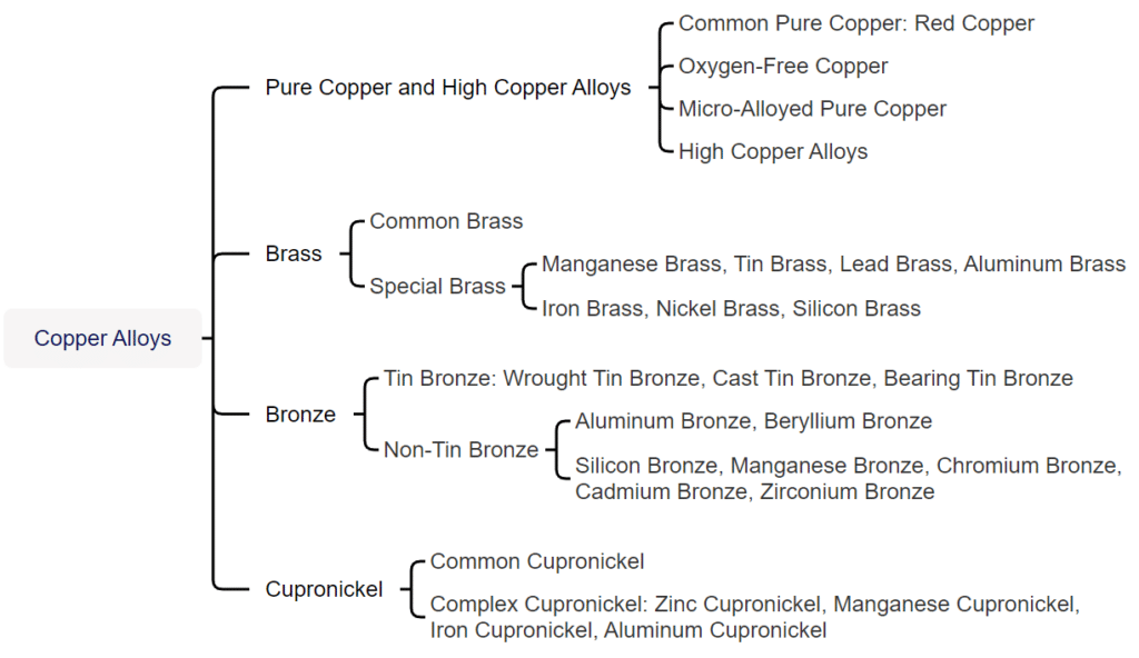
A kupronikkel feltalálása az ókori Kína kohászati technológiájának kiemelkedő eredménye. Az ókori Kínában a kupronikkelre "Gan"-ként hivatkoztak. A "Tang régi könyve - Értekezés a ruházatról" szerint: "Csak az első rangú tisztviselők kocsiját húzó ökröket lehet kupronikkel díszíteni". Ez azt jelenti, hogy a Tang-dinasztia idején kikötötték, hogy csak az első rangú udvari tisztviselők ökreit lehet kupronikkel díszíteni, ami azt jelzi, hogy a kupronikkel igen értékes volt abban az időben. A jünnani emberek találták fel és állították elő a kupronikkel, így ők voltak a legkorábbiak Kínában és a világon, amit a tudományos közösség hazai és nemzetközi szinten is elismer. Az ősi Yunnanban előállított kupronikkel volt a leghíresebb is, amelyet "Yun kupronikkel" néven ismertek.
Az ókori Kínában gyártott kupronikkel tárgyakat az egész országban értékesítették és külföldre is exportálták. A kutatások szerint a Hszincsiangtól nyugatra fekvő Daxia Királyságban már a Qin- és a Han-dinasztia idején öntöttek kupronikkel érméket, amelyek akár 20% nikkelt is tartalmaztak. Alakjuk, összetételük és a korabeli történelmi körülmények alapján nagyon valószínű, hogy Kínából szállították őket. A Tang- és a Song-dinasztia idején már exportáltak kínai nikkel-kupronikkeleket az arab térségbe, ahol a perzsák a kupronikkelre "kínai kő"-ként hivatkoztak. A 16. század után a kínai kupronikkel világszerte forgalomba került, és széles körű elismerésben részesült. Guangzhou-n keresztül exportálták, és a Brit Kelet-indiai Társaság Európában is értékesítette. Az angol "Paktong" vagy "Petong" kifejezés a kantoni "cupronickel" átírása, ami a Kínából származó cupronickelt jelenti, és konkrétan a Yunnanban előállított réz-nikkel ötvözetre utal.
A 17-18. században a nikkel-kupronikkel széles körben elterjedt Európában, és értékesnek számított. "Kínai ezüstnek" vagy "kínai kupronikkelnek" nevezték, és jelentősen befolyásolta a modern nyugati vegyipart. A 16. század után néhány európai vegyész és kohász elkezdte tanulmányozni és utánozni a kínai kupronikkel.
1823-ban a német Heineger testvérek sikeresen lemásolták a jünnani kupronikkel előállítását. Nem sokkal később a Nyugat nagyüzemi gyártásba kezdett, és ezt az ötvözetet "német ezüstnek" vagy "nikkelezüstnek" nevezték el, míg a valódi jünnani kupronikkel homályba veszett. Miután a nyugati országok sikeresen lemásolták a jünnani kupronikkel ötvözetet, a kínai kupronikkel exportmennyisége jelentősen csökkent. A 19. század végére a német ezüst felváltotta a kínai kupronikkel a nemzetközi piacon, ami a kínai kupronikkelbányászat és kohászat hanyatlásához vezetett.
2.3 A cupronickel alkalmazása az ékszerekben
Ha a nikkelt rézbe olvasztják, és a tartalom meghaladja a 16%-t, a kapott ötvözet olyan fehér lesz, mint az ezüst. Minél magasabb a nikkeltartalom, annál fehérebb a szín. A tiszta réz és nikkel kombinálásával a szilárdság, a korrózióállóság és a keménység is jelentősen javítható. Ezért, miközben a réz mechanikai és fizikai tulajdonságai viszonylag jók, vonzó megjelenésű, korrózióálló és kiváló mélyhúzási tulajdonságokkal rendelkezik, így kiváló anyag az ékszerek számára. Gyakran széles körben használják ezüst és platina utánzatú ékszerek készítésére, amelyek keménysége és csillogása nagyon közel áll az ezüst ékszerekéhez, de sokkal alacsonyabb áron.
A kupronikkel anyagokból készült ékszerekben a leggyakrabban használt anyag a cink-kupronikkel, amelynek tipikus fajtáit és összetételét a 2-11. táblázat, a cink-kupronikkel tulajdonságait pedig a 2-12. táblázat mutatja.
2-11. táblázat A hazai cink-kupronikkel kémiai összetétele
| Fokozatok | Kémiai összetétel /% | ||||||||||||
|---|---|---|---|---|---|---|---|---|---|---|---|---|---|
| Ni+Co | Fe | Mn | Zn | Pb | Si | P | S | C | Mg | Sn | Cu | Összes szennyeződés | |
| BZn 18-18 | 16. 5 ~ 19. 5 | 0.25 | 0.50 | Margin | 0.05 | - | - | - | - | - | - | 63. 5 ~ 66. 5 | - |
| BZn 18-26 | 16. 5 ~ 19. 5 | 0.25 | 0.50 | Margin | 0.05 | - | - | - | - | - | - | 53. 5 ~ 56. 5 | - |
| BZn 15-20 | 13.5 ~ 16. 5 | 0.5 | 0.3 | Margin | 0.02 | 0.15 | 0.005 | 0.01 | 0.03 | 0.05 | 0.002 | 62.0 ~ 65.0 | 0.9 |
| BZnl5-21-1.8 | 14. 0 ~ 16.0 | 0.3 | 0.5 | Margin | 1. 5 ~ 2.0 | 0.15 | - | - | - | - | - | 60. 0 ~ 63.0 | 0. 9 |
| BZnl5 -24-1,5 | 12. 5 ~ 15.5 | 0.25 | 0. 05 ~ 0. 5 | Margin | 1. 4 ~ 1. 7 | - | 0.02 | 0. 005 | - | - | - | 58. 0 ~ 60. 0 | 0.75 |
| (Liu Ping, 2007; Wang Biwen, 2007; Tian Rongzhang és Wang Shitang, 2002; Nemzeti színesfém-szabványosítási műszaki bizottság, 2012) | |||||||||||||
2-12. táblázat A cink-kupronikkel fizikai és mechanikai tulajdonságai
| Teljesítmény | Ötvözet | |
|---|---|---|
| BZnl5-20 | BZnl7-18-1.8 | |
| Folyékony fázispont /℃ | 1 081.5 | 1 121.5 |
| Szilárd fázis pont/℃ | - | 966 |
| Sűrűség ρ/ g-cm-3 | 8. 70 | 8.82 |
| Hőkapacitás c/J - (g-°C)-1 | 0.40 | - |
| 20-100℃ Lineáris tágulási együttható α/℃-1 | 16. 6X10⁻⁶ | - |
| Hővezető képesség λ/W-(m-℃)-1 | 25 ~ 360 | - |
| Ellenállás ρ/μΩ-m | 0.26 | - |
| Ellenállás hőmérsékleti együttható αR/℃-1 | 2X10⁻⁴ | - |
| Rugalmassági modulus E/GPa | 126 ~ 140 | 127 |
| Szakítószilárdság σb/MPa | 380 ~ 450 lágy állapot,800 kemény állapot | 400 puha állapot,650 kemény állapot |
| Nyúlás δ/% | 35 ~ 45 lágy állapot,2 ~ 4 kemény állapot | 40 puha állapot,2.0 kemény állapot |
| Folyáshatár σ0.2 /MPa | 140 | - |
| Brinell-keménység HB | 70 lágy állapot,160 ~ 175 kemény állapot | - |
| Vágási teljesítmény(H HPb63 - 3)/%-hoz képest | - | 50 |
| (Liu Ping, 2007; Wang Biwen, 2007; Tian Rongzhang és Wang Shitang, 2002; Nemzeti színesfém-szabványosítási műszaki bizottság, 2012) | ||
2.4 A Cupronickel anyagok fejlesztése
A nikkel-kupronikkel számos kiváló tulajdonsággal rendelkezik, mint ékszeranyag, de vannak hátrányai is. Mivel a fő adalékelem, a nikkel ritka anyag, a kupronikkel ára viszonylag magas. Ezenkívül a nikkel káros hatásaival kapcsolatos széles körű aggodalom miatt a különböző országokban az emberi bőrrel érintkezésre készült termékek, például cipzárak, szemüvegkeretek, érmék, evőeszközök és ékszerek bőrallergiás reakciókat okozhatnak. Ezért a nikkel-kupronikkel anyagok az elmúlt években kihívásokkal szembesültek, ami különösen fontossá tette az új nikkelmentes kupronikkel ötvözetek kifejlesztését.
Eddig a nikkelmentes kupronikkelre vonatkozó kutatások többsége a Cu-Mn-Zn ötvözetre összpontosított, és az egyes ötvözőelemek fő szerepe a következő.
(1) Mangán
A mangán a nikkelmentes kupronikkel ötvözetek fő adalékanyaga. Képes csökkenteni a réz felületének sárga és vörös színű összetevőit, fehérítő vagy fakító szerként viselkedve, az ötvözet színét színesről színtelenre változtatva. A mangán a szilárd oldat erősítésével javíthatja az ötvözet mechanikai tulajdonságait. A cink részleges helyettesítése mangánnal javíthatja az öregedési repedések körülményeit. A mangán elnyomhatja a cink elpárolgását az olvasztás során, és csökkentheti az anyagköltségeket. Ha azonban a mangántartalom meghaladja a 15% értéket, az ötvözet α+β többfázisú szerkezetet mutat, ami rosszabb feldolgozási teljesítményhez vezet. A mangán károsan hat az ötvözet öntési teljesítményére; az olvasztás során a mangán könnyen oxidálódik, és magas olvadáspontú mangán-oxid zárványokat képez, amelyek nagy sűrűségűek és nehezen úsznak ki az olvadt fémből, így az öntvények könnyen zárványhibásak lehetnek. Ezenkívül a mangán növeli az ötvözet zsugorodási sebességét, csökkentve annak folyékonyságát, és a magas mangántartalom ronthatja az ötvözet feldolgozási teljesítményét. Ezért a technológiai teljesítmény szempontjából a mangántartalom nem lehet túl magas.
(2) Cink
A cink szilárd oldatmegerősítéssel javíthatja az ötvözetek szilárdságát és keménységét, csökkentheti az ötvözetek olvadáspontját, javíthatja az alakítási teljesítményt, és csökkentheti az ötvözetek költségeit. Ha a cinktartalom túl alacsony, az erősítő hatás gyenge; a cinktartalom növelése javíthatja az erősítő hatást. A cink azonban jelentősen csökkenti a réz korrózióállóságát, különösen, ha a cink meghaladja a 22% értéket, ami az ötvözet α+βmultifázisú szerkezetbe való átalakulását okozza, ami rontja a feldolgozási teljesítményt és hajlamos a maradó feszültség által kiváltott öregedési repedések problémáira. Ha a cinktartalom kevesebb, mint körülbelül 30%, a cinktartalom növelése csökkenti a Cu-Mn-Zn ötvözet színének vörös komponensét, miközben növeli a sárga komponenst és a fényesség értékét. A cinknek fontos hatása van az ötvözetek színstabilitására is; a cinktartalom növekedésével csökken az ötvözet mesterséges izzadságban való elszíneződéssel szembeni ellenállása.
(3) Alumínium
Az alumínium az egyik legfontosabb színezőelem az arany utánzatú ötvözetekben. Az alumíniumtartalom növekedésével a Cu-Zn-Al terner ötvözet fényessége és sárga komponense nő, míg a vörös komponens csökken. Az alumínium cink-egyenérték együtthatója nagyon magas; minden 1% alumínium 6% cinknek felel meg, így az α-fázisú régió jelentősen csökken az alumínium hozzáadása után. Az alumínium sűrű oxidfilmet képezhet az ötvözet felületén, ami javíthatja az ötvözet öregedési repedéseit és a dezinkrációs korróziós problémáit, és szilárd oldatmegerősítést is eredményez, ami előnyös az ötvözet mechanikai tulajdonságainak javítására. Ha az alumíniumtartalom túl alacsony, az erősítő hatás elégtelen és nem elégséges az öregedési repedésekkel szembeni ellenálláshoz. Ha azonban a tartalma meghaladja a 4%-t, az ötvözet olvasztása során nehézzé válik az olvadt fém tisztítása, és összetett α+β fázisszerkezet jelenik meg, ami rontja a hidegmegmunkálási teljesítményt.
(4) Ón
Az ón cink-egyenérték együtthatója 2, így kis mennyiségű ón hozzáadása kevés hatással van a szerkezetre, és az ötvözet egyfázisú marad. Az ónnak bizonyos szilárd oldatot erősítő hatása van. Mégis, ha tartalma meghalad egy bizonyos szintet, hajlamos alacsony olvadáspontú fázisokat képezni a szemcsehatárokon, ami káros a mechanikai tulajdonságokra. A kis mennyiségű ónnak szintén kevés hatása van a Cu-Mn-Zn ötvözet színére; fő szerepe az, hogy SO2 védőfilmet képez az ötvözet felületén, ami jelentősen javíthatja az ötvözet elszíneződéssel szembeni ellenállását. Az ón növelheti az ötvözet folyékonyságát és javíthatja az öntési teljesítményt, de növeli az ötvözet költségét.
(5) Ritkaföldfémek
A ritkaföldfém cérium nyomokban finomíthatja a szemcseméretet, javíthatja az ötvözet szakítószilárdságát és nyúlását, és fokozhatja az ötvözet hidegen megmunkálható teljesítményét.
By comprehensively utilizing these elements, researchers at home and abroad have developed a series of multi-element nickel-free white Cu-Mn-Zn alloys, such as Cu- 12Mn -8Zn – 1Al – 0.04%Ce, Cu – 15Mn – 15Zn – 1Al, Cu – 20Mn – 20Zn – 0.3Al – 0.2Sn – 0.05Mg, etc.
3. Bronz
A többi rézötvözetet bronznak nevezik, kivéve a sárgaréz és a kupronikkel. A bronz általában a vörösréz ónnal, ólommal és más kémiai elemekkel alkotott ötvözetét jelenti, amely kékes-szürke színéről kapta a nevét. A bronzot ónbronzra és ón nélküli bronzra osztják, az ónbronz a legrégebbi művészi öntvény ötvözet a történelemben. A nem ónozott bronz a modern időkben kifejlesztett újfajta bronz, amely olyan elemeket használ, mint a szilícium és az alumínium, hogy helyettesítse a drágább ónt, miközben tovább javítja az ónozott bronz egyes tulajdonságait. A bronz legnagyobb előnye a kiváló kopásállósága, emellett nagyfokú korrózióállósággal rendelkezik gőzben, tengervízben és lúgos oldatokban, ami fontos oka annak, hogy az ősi bronzból készült műalkotások a mai napig tökéletesen megmaradtak. Ezenkívül a bronznak alacsonyabb az olvadáspontja, jobb az öntési teljesítménye és jó mechanikai tulajdonságai.
A művészi öntvényekhez használt bronz jellemzően ónbronz, szilikonbronz, alumíniumbronz stb.
3.1 Ónbronz
Az ónbronz egy ősi öntészeti rézötvözet, amelynek története több mint 5000 éves. A kínai nemzet ősi öntőművészetének legtöbb kincsét ónbronzból öntötték, mint például a Shang-dinasztia Simuwu Dingjét, a tavaszi és őszi és a Háborús Államok korszakának rituális edényeit, valamint a bianzhongokat (bronzharangokat).
(1) Az ónbronz szerkezete és teljesítményjellemzői
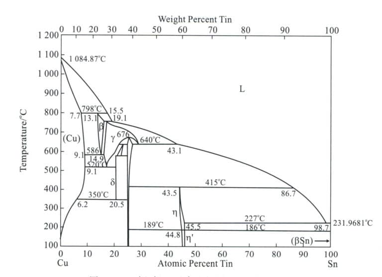
Az ónbronz alapja egy réz-ón ötvözet; a diagram (2-11. ábra) a Cu-Sn bináris fázisdiagram, és α, β, γ, δ fázisok lépnek ki, amelyek közül az α fázis a tiszta rézben oldott ón szubsztitúciós szilárd oldata, arcközpontú köbös ráccsal, így megtartva a tiszta réz jó képlékenységét. A β fázis egy szilárd oldat, amelynek alapja a Cu elektronikus vegyület5 A magas hőmérsékleten létező, testközpontú köbös ráccsal rendelkező Sn, amely a hűtés során bomlik. A Γ fázis egy CuSn alapú szilárd oldat, amely a β fázishoz hasonló tulajdonságokkal rendelkezik. A δ fázis egy szilárd oldat, amelynek alapja a Cu31 Sn8 , összetett kocka ráccsal, szobahőmérsékleten létező, kemény és rideg.
(2) Az ötvözőelemek szerepe az ónbronzban
① Cink. A cink hozzáadása az ónbronzhoz csökkentheti az ónbronz kristályosodási hőmérséklettartományát, javíthatja az ötvözet folyékonyságát, és csökkentheti a zsugorodási üregek kialakulására való hajlamot. Ezenkívül a cinknek viszonylag nagy a gőznyomása az olvadás során, és a képződő cinkgőz megakadályozhatja a réz és az ón elemek oxidációját, tisztítja az ötvözetet és csökkenti a pórusok kialakulására való hajlamot. A cink hatása az ónbronz szerkezetére és tulajdonságaira hasonló az ónéhoz, 2% cink hozzáadása egyenértékű a 1% ón szerepével. A cink ára azonban sokkal alacsonyabb, mint az óné, ezért a költségek csökkentése érdekében a cinket az ón helyettesítésére lehet használni. Ha a cinktartalom meghaladja az 5%-t, akkor a minták elmosódhatnak, növelheti a korrózióra való érzékenységet, és megnehezítheti az elegáns zöld külső réteg létrehozását.
② Vezető. Az ólomnak nagyon alacsony a keménysége, és részecske formájában oszlik el az ónbronzban, ami javítja az ötvözet kopásállóságát és megkönnyíti a bronz megmunkálását. Ugyanakkor az ólom alacsony olvadáspontja fokozza az ónbronz folyékonyságát. A megszilárdulás során az ólom felhalmozódik a dendritek közötti résekben, csökkentve a zsugorodást és megakadályozva a szivárgást, a legjobb szivárgásgátló hatást általában 5% körüli ólomtartalomnál érik el. Az ólomnak viszonylag nagy a fajsúlya a bronzban, és a túlzott ólom gravitációs szegregációt okozhat, ezért fontos, hogy az ólomtartalmú ónbronzot öntés előtt megkeverjük, és vízhűtést vagy fémformákat használjunk a hűtés felgyorsítására és a szegregáció megelőzésére.
③ Nikkel. A nikkel végtelenül jól oldódik a bronz szilárd oldatában, elősegítve az α-dendritek kialakulását; így kis mennyiségű nikkel hozzáadása csökkentheti az ón és az ólom szegregációját. 1%~2% nikkel hozzáadása finomíthatja a szemcséket, javíthatja a mechanikai tulajdonságokat, a korrózióállóságot és a hőstabilitást, és fokozhatja a bronz öntési teljesítményét. Nagyobb mennyiségű nikkel hatására a bronz fehérebbnek tűnik.
④ Vas. A vas fő funkciója hasonló a nikkeléhez; képes finomítani a szemcséket, növelni a szilárdságot és javítani a színezési teljesítményt. Tartalmát azonban 5% alatt kell tartani; ellenkező esetben a bronzot törékennyé teszi, és csökkenti a korrózióállóságot.
⑤ Alumínium. Az ónbronzban az alumínium káros szennyeződés, amely megnehezíti a színezést. Amíg 0,5% alumínium van jelen, a felület sötétvörösből aranysárgára, majd ezüstfehérre változik. Az alumínium azonban javíthatja az ólommentes bronz szilárdságát, korrózióállóságát és öntési teljesítményét.
⑥ Foszfor. 0,03%~0,06% foszfort kell hozzáadni az ónbronzhoz, hogy dezoxidálja azt és javítsa az öntési teljesítményt; a túlzott mennyiség könnyen törékeny fázist hozhat létre Cu3 P és csökkenti a színező hatásokat.
⑦ Szilícium. A szilícium hozzáadása a bronzhoz rontja annak mechanikai és öntési tulajdonságait, de növelheti a korrózióállóságot. A szilícium sötétvöröstől a barnáig terjedő, néha lilának tűnő színt kölcsönöz a felületnek a nagyon sűrű SiO2 a felületet borító film, ami megnehezíti a színezést.
Az ónbronz szép megjelenésű és kiváló feldolgozási teljesítményű. Az ókortól kezdve széles körben használják az öntő kézművességben. A 2-13. táblázat felsorol néhány, művészi öntvényekhez gyakran használt ónbronz anyagot.
2-13. táblázat Ónbronz művészi öntvényekhez
| Név, osztályzatok | Főbb kémiai összetevők /% | Szennyeződés /%≯ | Megjegyzések | ||||||||
|---|---|---|---|---|---|---|---|---|---|---|---|
| Sn | Zn | Pb | A1 | Cu | Sb | Fe | Al | Összesen | |||
| ZCuSn2Zn3 | 1.8 ~ 2.2 | 2.5 ~ 3.5 | Margin | China Standard | |||||||
| ZCuSn3A12 | 2.5 ~ 3.5 | 1.5 ~ 3.5 | Margin | China Standard | |||||||
| ZCuSnll2Mnl | 10 ~ 15 | 0. 15 ~ 0. 25 | 0. 2 ~ 0. 3 | Mn 1.0 ~ 1. 25 | Margin | China Standard | |||||
| ZCuSn5Zn5Pb5 | 4.0 ~ 6.0 | 4.0 ~ 6.0 | 4.0 ~ 6.0 | Margin | China Standard | ||||||
| ZCuSn10Zn2 | 9.0 ~ 11.0 | 1.0 ~ 2.0 | Margin | China Standard | |||||||
| BC1 | 2.0 ~ 4.0 | 8.0 ~ 12.0 | 3.0 ~ 7.0 | 79. 0 ~ 83. 0 | 2.0 | Japán szabvány | |||||
| BC6 | 4.0 ~ 6.0 | 4.0 ~ 6.0 | 4.0 ~ 6.0 | 82. 0 ~ 87.0 | 2.0 | Japán szabvány | |||||
| BC7 | 5.0 ~ 7.0 | 3.0 ~ 5.0 | 1.0 ~ 3.0 | 86. 0 ~ 90. 0 | 1.5 | Japán szabvány | |||||
| G - CuSn5ZnPb | 4.0 ~ 6.0 | 4.0 ~ 6.0 | 4.0 ~ 6.0 | 84. 0 ~ 86. 0 | 0.3 | 0.3 | P0. 05 | S0. 10 | Németország Standard | ||
| C90300 | 7.5 ~ 9.0 | 3.0 ~ 7.0 | 86.0 ~ 89. 0 | 0.2 | 0.15 | 0. 005 | Si0. 005 | 1.76 | American Standard | ||
| (Tian Rongzhang és Wang Zhutang, 2002) | |||||||||||
Az ónbronzot műalkotások öntésére használják, és képes ellenállni a magas hőmérsékletnek, a magas páratartalomnak és a városi hulladékgázoknak (főként CO2, SO2, NO-gázok), sőt még a savas esőt is. Normál légkörben az ónbronz korróziós sebessége 0,001 mm/a; tengerparti légkörben 0,002 mm/a; ipari légkörben 0,002 ~ 0,006 mm/a.
A nagyméretű kültéri öntött műalkotások a napfény, a hőmérséklet-különbségek és a korrozív légkörben történő hegesztés okozta feszültségek miatt megrepedhetnek. Az ónbronznak alacsony a hajlama a feszültség okozta repedésre, ami hatékonyan csökkentheti ezt a kockázatot. A hongkongi Tian Tan Buddha például 8% Sn és 4%, a többi réz, öntött és hegesztett bronzból készült, és 1989-ben készült el. Azóta is biztonságban áll a hongkongi Lantau-sziget Muk Yu csúcsán.
3.2 A bronz alkalmazása a kézműves díszítésben
A bronz gyönyörű megjelenése és kiváló feldolgozási teljesítménye miatt az ókortól napjainkig széles körben használták kézműves ékszerek anyagaként.
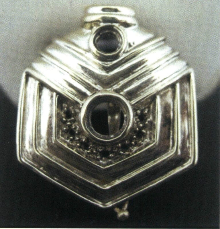
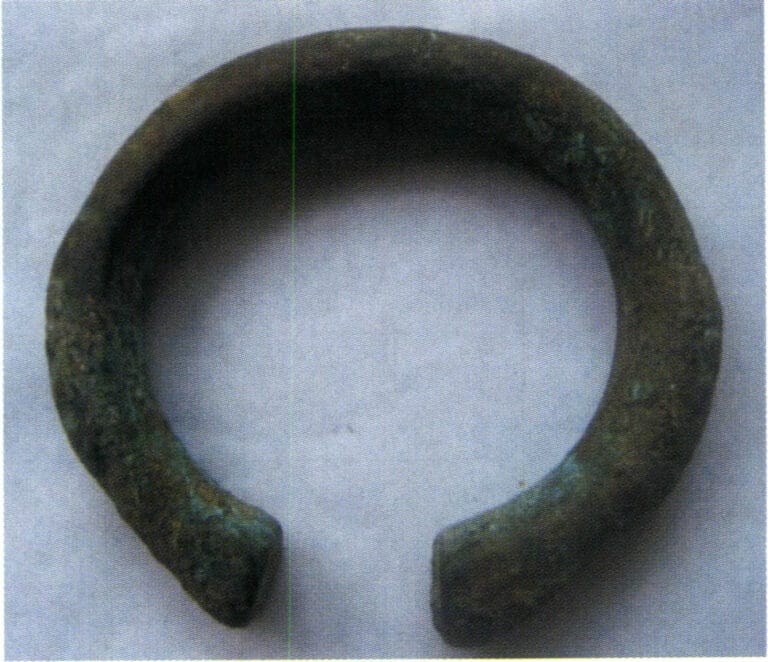
Az ókorban, amellett, hogy széles körben használták használati tárgyként, finom és bonyolult díszek készítésére is használták, mint például a Han-dinasztia bronz karkötői és a Liao-dinasztia bronzgyűrűi. Napjainkban a bronz alkalmazása a kézművességben és az ékszerekben nagy fejlődési potenciállal rendelkezik, különösen a gazdasági szintek javulásával, a bronzöntés gyors fejlődésével, a nagy piaci kereslettel, a termékek széles választékával és a másolás, az utánzás és az alkotás különböző módszereivel. Széles körben használják városi szobrok, templomi rituális edények, Buddha-szobrok, díszítő festmények és gyűjtőeszközök formájában. Az ékszerek tekintetében a bronzot különböző díszek és kiegészítők készítésére is használják. A híres görög divatmárka, a Folli Follie például ékszerek, órák és kiegészítők tervezésével, gyártásával és forgalmazásával foglalkozik. A vállalat a Precious Bronze sorozatot indította el, amely a bronzot és az ezüstöt ötvözi. A nyakláncok, karkötők és fülbevalók szabálytalanul kerekek, nosztalgikus érzést keltenek, amely egy aranyló napfényben fürdő földre emlékeztet. A különböző anyagok keveredése és az ezüst frissessége gyönyörű íveket hoz létre. Ezek a fényűző kincsek a Folli Follie ragyogó jellemzőit hordozzák, az igazi divatrajongók eleganciáját és szépségét sugározzák.

Hong Kong Tian Tan Buddha (bronz)
Liao dinasztia bronz gyűrű
Bronz karkötő a Han-dinasztiából
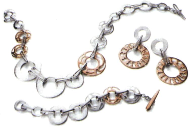
A Folli Follie cég értékes bronz ékszerei (bronz + ezüst)
Copywrite @ Sobling.Jewelry - Egyedi ékszergyártó, OEM és ODM ékszergyár
IV. szakasz A réz ékszerek kézművessége
1. Az elveszett viaszöntési folyamat a réz ékszerekhez
A gipsz öntőforma öntés az ékszerkészítés fő módszerévé vált, és a réz ékszerek tipikus folyamatfolyamata a következő:
Eredeti modell készítése→ Gumiformák készítése (préselőformák, vulkanizálás, nyitóformák)→ Viaszformák készítése (viaszinjektálás, viaszfinomítás)→ Viaszmodellfák ültetése→ Formába öntés (öntőporiszap keverése, vákuumozás, öntőiszap öntése, vákuumozás, viaszmentesítés, kiégetés)→ Olvasztás és öntés (ötvözet előkezelés, olvasztás, öntés)→ öntvény tisztítás (öntőpor eltávolítása, savas merítés, előpolírozás)→ utófeldolgozás (formakezelés, beállítás, polírozás, galvanizálás).
1.1 Eredeti modell
A munkadarab összetettsége, a specifikációk és az ügyfél minőségi követelményei alapján határozza meg a megfelelő eredeti változat gyártási módszerét. Az ékszer eredeti modell gyártási módszereket három kategóriába soroljuk: kézzel faragott viaszmodellek, számítógépen generált modellek és kézzel készített ezüst modellek. A kézzel faragott viaszmodelleket példaként véve a fő folyamat a következő szempontokat foglalja magában: a megrendelés megtekintése és az anyag vágása→ durva kidolgozás→ finom kidolgozás→ az alsó súly eltávolítása→ a kőbeillesztési pozíció megnyitása→ javítás.
(1) A megrendelés megtekintése és az anyag vágása
Megérti a megrendelésen alapuló vevői követelményeket, mint például a méret, kőméret, viasz súlyhatár stb. Válassza ki a munkadarabnak megfelelő viaszanyagot, majd jelölje ki a vonalakat a viaszanyagon, és fűrészlap vagy ívfűrész segítségével vágja le a megjelölt vonalak mentén.
(2) Durva befejezés
Rajzolja meg a fő vonalakat az anyagon, beleértve a belső és külső kontúrokat is. Egy durva csíkkal varrja le a felesleges részeket. Telepítse a befejező fúrót az elektromos függő flexibilis tengelycsiszolóra az előzetes megmunkáláshoz, először hozzon létre egy durva körvonalat. Ezután váltson át az acélfúróra, és sekélyítse le a durva szalag és a befejezőfúró szerszám által hagyott mély nyomokat (2-13. ábra). Végül reszelővel távolítsa el az acélfúró által hagyott nyomokat, és tegye simává a felületet.
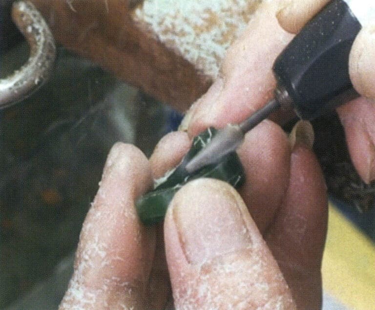
2-13. ábra Durva megmunkálás
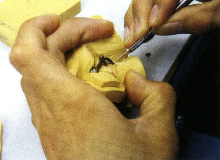
(3) Finomítás
A finommegmunkálás a durva megmunkáláson és további feldolgozáson alapul, hogy a teljes viaszminta finomabbá és esztétikusabbá váljon. Először egy iránytűvel felvesszük az egyes részek méreteit a viaszminta sablonján, és néhány segédvonalat húzunk. E segédvonalak alapján a felesleges viaszt egy utómunka-fúróval eltávolítjuk, majd egy acélfúróval kisimítjuk az előző folyamatból visszamaradt durva nyomokat. Nagy és kis spatulákkal szintezze ki a viaszmintán lévő sarkokat vagy kiálló részeket, és finomítsa azt szikével. Végül nagy és kis reszelőkkel simítsa el a teljes viaszmintát.
(4) Az alsó súly eltávolítása
Az alsó súly eltávolításának célja a munkadarab súlyának csökkentése. Szerelje fel a gömbfúrót és a kerékfúrót az elektromos függő flexibilis tengelycsiszolóra, és a gömbfúróval távolítsa el a felesleges viaszanyagot a modellfej alján vagy a gyűrűszár belső körénél (2-14. ábra). Általában a pave foglalatnál a fenntartott alsó vastagság 1,1 mm; a világos arany és a süllyesztett foglalatnál 0,7 mm; a gyűrűs foglalatnál és a csatornafoglalatnál 1,6 mm. Ezután fogászati fúróval, fúrófúróval, sebészkéssel stb. vágja le a viaszminta alsó keretét. Az alsó súly eltávolítása során fontos, hogy az eltérések elkerülése érdekében gyakran mérje meg a méreteket a fényarany pozícióban, a pave beállítási pozícióban, a csatorna beállítási pozícióban stb. belső mérőszögek segítségével.
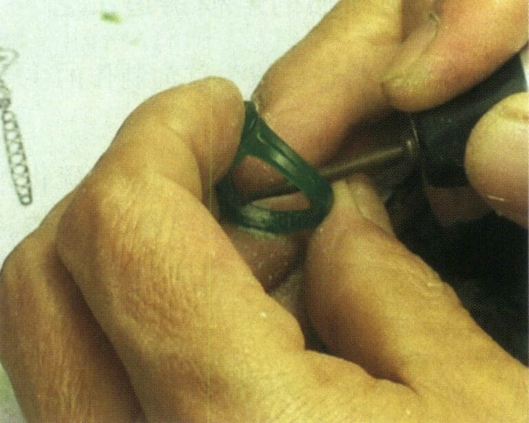
2-14. ábra Az alsó súly eltávolítása
(5) Készítse el a kő beállítási pozícióját
A kő méretének és a beállítási módszernek megfelelően nyissa meg a kő pozícióját, használjon megfelelő gyémántfúrót a csatornabeállításhoz és a keretbeállításhoz, fúrjon lyukakat a kijelölt kőpozícióban, majd használjon acélfúrót, kis reszelőket, szikét stb. a beállításokhoz; acélfúrót lehet használni a kő pozíciójának közvetlen megnyitására is.
(6) Javítás
A javítás magában foglalja bizonyos részletek kiigazítását annak érdekében, hogy a javított munkadarab jobban megfeleljen a megrendelés követelményeinek. A javítás során figyelmet kell fordítani a viasz súlya és mérete közötti viszony beállítására és összehangolására a megrendelésnek a termék súlyára és méreteire vonatkozó követelményei szerint.
(7) Polírozás
Törölje át a viaszlemez felületét nejlonkendővel, hogy sima és finom legyen.
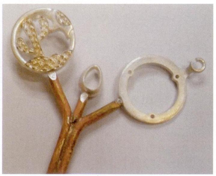
(8) Ezüst modell replikálása
Miután a kézzel faragott viaszmodell elkészült, ezüstmodellbe kell önteni, hogy a gumimintát lemásolják. Az öntött ezüstmodell felületét ezután finomítják (2-15. ábra), hogy biztosítsák a jó felületet, elkerülve, hogy az ezüstmodell hibái átkerüljenek az öntvényre. Az ezüstmodell alakját, méreteit és súlyát ellenőrzik, hogy megfeleljen a megrendelés követelményeinek. Ezenkívül kiegészítik azokat a folyamatokat, amelyeket a kézzel faragott viaszmodell nem tud elvégezni, mint például a tüskék ültetése, csatok és gombok készítése, fülbevalók lógatása stb.
(9) Hegesztőfecskendők
Az öntőcsatornát úgy tervezték, hogy az öntési folyamat során csatornát hagyjon az olvadt fém áramlásának. Az ékszeröntésnél, mivel a munkadarabon nincsenek beállított emelkedők, hogy pótolják az összehúzódást, az öntőcsatorna csatornává vált a folyékony fém töltéséhez, de a feladat összehúzódásához a sminkben a folyékony fém megszilárdulásának összehúzódását is el kell viselnie, az öntőcső helyes beállítása annak biztosítása, hogy az öntés minősége az alapvető feltételek az öntés sok a hibák az öntés az olvadt penész közvetlenül vagy közvetve a beállítás az öntőcső okozta irracionalitás a hibák, mint például a nem megfelelő töltés, lazítás, porozitás, és más gyakori hibák.
2-15. ábra Az ezüst modell befejezése
1.2 Gumiszerszám készítés
(1) Nyersgumi töltése és préselése
Olajos tollal rajzolja meg a modellforma széle mentén az elválasztó vonalat, mint a gumiforma vágási pozícióját. A választóvonal pozícióját a forma eltávolításának megkönnyítése elve alapján határozza meg. Készítse elő a gumilapot és a gumirészecskéket az ezüstmodell méreteinek megfelelően, helyezze az ezüstmodellt a megfelelő pozícióba a gumilapon, és töltse ki a hézagokat, mélyedéseket és a kőbeállási pozíciókat a mestermodellen olyan módszerekkel, mint a dugaszolás, tekercselés, foltozás és töltés, biztosítva, hogy a szilikon gumilap és a mestermodell között ne legyenek hézagok (2-16. ábra). Ezután a maradék gumilemez felhelyezése következik; a gumiminta hosszú élettartamának biztosítása érdekében általában több mint négy réteg szilikonfóliával préselik. A formakeretbe való préselés után a gumiszerű forma vastagsága kb. 2 mm-rel magasabb a keret síkjánál. A művelet során a szilikon gumilapot tisztán kell tartani, és kerülni kell a közvetlen érintkezést a szilikon gumilap felületével; ehelyett a szilikon fólia felragasztása után a felületen lévő védő gumilapot le kell tépni.

2-16. ábra töltőgumi
(2) Vulkanizálás
Először melegítse elő a vulkanizálót, majd helyezze bele az öntőkeretet az előpréselt szilikonlappal, és húzza meg a fogantyút, hogy a fűtőlapot az öntőkerethez nyomja. Óvatosan ellenőrizze, hogy a fűtőlap szorosan van-e nyomva (2-17. ábra). Az általánosan használt gumi vulkanizálási hőmérséklettartománya 143~173 ℃, az optimális hőmérséklet a gumi típusától függ. Fűtés előtt néhány percig nyomja, majd fokozatosan növelje a nyomást. A vulkanizálási időt a modell vastagsága alapján válassza ki; például 12 mm vastagság esetén 30 perc, 18 mm vastagság esetén 45 perc, 36 mm vastagság esetén 75 perc. A vulkanizálási idő letelte után gyorsan vegye ki a gumimintát, és miután az természetesen lehűlt szobahőmérsékletre, folytathatja a formanyitási műveletet.
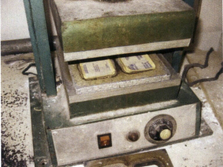
2-17. ábra Kénezés
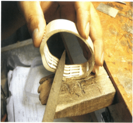
(3) A gumiszerszám kinyitása
A gumiszerszám felnyitása magában foglalja a préselt gumiszerszám levágását az eredeti modell kivétele érdekében (2-18. ábra), valamint a gumiszerszám több részre osztását a minta alakjának összetettsége szerint, hogy a viaszbefecskendezés után a viaszformát zökkenőmentesen el lehessen távolítani. A gumiszerszám felnyitása általában négylábú pozícionálási módszert alkalmaz.
2-18. ábra Formanyílás
1.3 Viaszformák készítése
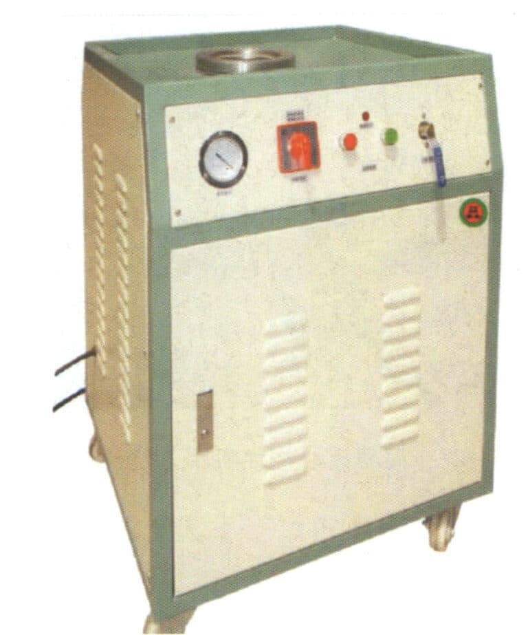
Az ékszerek finomsága miatt a viaszformák készítésekor a viaszinjektáló gép nyomását kell használni a viaszfolyadék befecskendezéséhez a gumimodell üregébe. Számos viaszbefecskendező gép létezik, beleértve a közönséges légnyomásos viaszbefecskendező gépeket, a vákuumos viaszbefecskendező gépeket és a digitális automatikus viaszbefecskendező gépeket. Helyezze a viaszanyagot a viasztartályba. A viaszanyagot tisztán kell tartani, a viasztartály és a fúvóka hőmérsékletét pedig a kívánt hőmérsékletre kell beállítani.
A viasz felvitele előtt nyissa ki a szilikonformát, és ellenőrizze annak épségét és tisztaságát. A viaszforma könnyebb eltávolítása érdekében fújjon a forma kisebb, bonyolultabb területeire oldószert (vagy szórjon rá kis mennyiségű hintőport).
Indítsa el a vákuumszivattyút a viasz befecskendezése közben, és ellenőrizze, hogy a viasz hőmérséklete 0 ~ 75 ℃ között van-e. Állítsa be a befecskendezési időt és a légnyomást a szerszámban lévő viaszdarabok összetettségének megfelelően, majd egyenletesen szorítsa be a szerszámot a viaszbefecskendezési művelet elvégzéséhez (2-19. ábra). A viaszdarab kb. 1 perc hűtés után kivehető a formából. A szerszám eltávolításakor óvatosan kell eljárni, hogy elkerüljük a viaszdarab eltörését vagy deformálódását.
Miután eltávolította a viaszformát, gondosan vizsgálja meg azt. Ha vannak hibák, mint például villanás, szorításnyomok, nem világos virágfejek vagy átfedő virágfejek, ezeket sebészi pengével kell levágni; a homoklyukak és törött karmok esetében viaszhegesztővel javíthatók; az eltömődött kis lyukakat hegesztőtűvel lehet behatolni; a viaszforma deformációja esetén 40~50 ℃-os forró vízben korrigálható. Végül alkoholba áztatott vattával eltávolítjuk a viaszforgácsokat a formából.
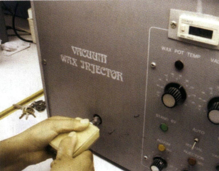
2-19. ábra Viaszbefecskendezés
1.4 Plating viasz modell fa

2-20 ábra Viaszmodell fa ültetése
1.5 Gyártása gipsz öntőformák
(1) Beruházás - keverőpor és injektálás
A formakészítési folyamatban néhány tipikus gépet és berendezést használnak, beleértve az egyszerű porkeverőket, vákuumos elszívókat, automatikus vákuumos porkeverőket stb. A tipikus gipszöntőpor-keverési és injektálási folyamatot a 2-21. ábra mutatja.
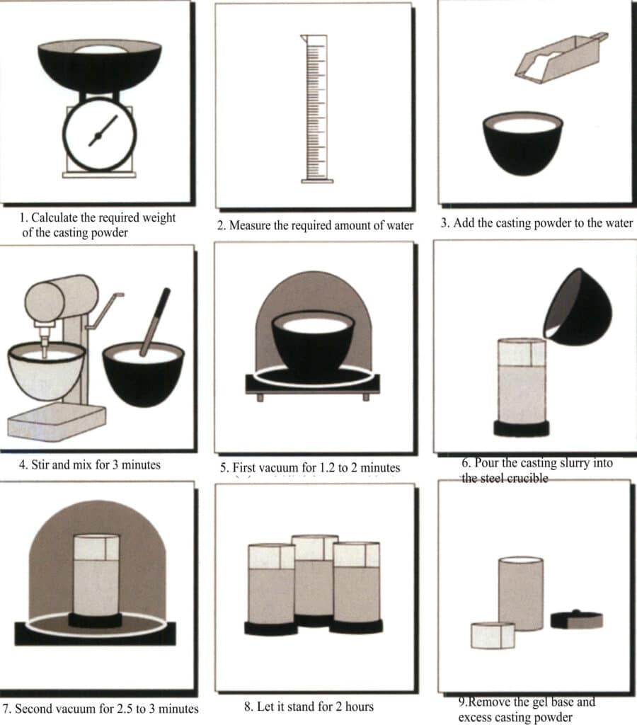
2-21. ábra A gipszöntőpor keverési és injektálási folyamatának sematikus ábrája
A viaszmodellfán keletkező statikus elektromosság miatt, amely könnyen vonzza a port, a fugázás előtt felületaktív anyagba vagy hígított mosószerbe lehet meríteni, majd desztillált vízzel lemosni és megszárítani. A porkeverés és a fugázás során figyelmet kell fordítani a gipsziszap megkötési idejének megfelelő szabályozására. Ha túl gyorsan szilárdul meg, a gáz nem tud időben távozni; ha túl lassan szilárdul meg, a por könnyen leülepedhet az iszapban, ami a szilárd-folyadék arány helyi változását eredményezi, ami az ékszerek tetején és alján eltérő érdességet okoz.
Miután az öntőforma elkészült és a vákuumos műveletet elvégezték, hagyni kell állni 1,5~2 órát, hogy a gipszforma teljesen megszilárduljon és megkeményedjen. Ezután távolítsa el a gumialapot, az acéllombik körüli csomagolóanyagot és a szétfröccsentett gipsziszapot, és tegyen jeleket az öntőforma oldalára és felületére.
(2) A viasz eltávolítása a formából
Miután az iszap megszilárdult, a viasz eltávolítására kétféle módszer létezik: gőzzel történő viaszmentesítés vagy száraz viaszmentesítés kiégető kemencében.
A gőzzel történő viaszmentesítés hatékonyabban távolítja el a viaszt, és a környezetet is kíméli. Vegye figyelembe, hogy a víz forralása nem lehet túl erőteljes, és a gőzzel történő viaszmentesítés idejét ellenőrizni kell; ellenkező esetben a kifröccsenő víz bejuthat a formába, és károsíthatja a forma felületét. Ezen kívül a viaszos öntésnél a gőzzel történő viaszmentesítés alkalmazása felhígíthatja az öntőporban lévő bórsavas védőanyagot, ami olyan problémákhoz vezethet, mint a zavaros vagy elszíneződött drágakövek.
A kiégetéses viaszmentesítés olyan módszer, amely közvetlenül kiégető kemencét használ a forma melegítésére, lehetővé téve a viaszanyag megolvadását és kifolyását a formából. A viaszanyag alacsony forráspontja miatt e módszer alkalmazásakor, ha a viaszfolyadék hevesen forr, az károsíthatja az öntőforma felületét, vagy ha a viaszfolyadék nem egyenletesen ürül ki, az beszivároghat az öntőforma felületi rétegébe, mindkettő rontja az öntvény felületi minőségét. Ezért fontos a fűtési hőmérséklet és sebesség szabályozása a viaszmentesítési szakasz során, valamint a megfelelő szigetelési platform kialakítása.
(3) Formázás kiégése
A kiégetés célja a nedvesség eltávolítása a gipszformából és a maradék viaszból, a kívánt magas hőmérsékletű szilárdság és a penész légáteresztő képességének elérése, valamint a penész hőmérsékleti követelményeinek teljesítése az öntés során. A kiégető rendszer és a berendezés nagymértékben befolyásolja a gipszforma végső teljesítményét.
Az ékszeriparban használt gipszégető kemencék általában ellenálláskemencéket alkalmaznak, néhányan pedig olajtüzelésű kemencéket használnak. A kemence típusától függetlenül a kemencében a hőmérséklet eloszlásának a lehető legegyenletesebbnek kell lennie. Általában az ellenállásos kiégető kemencét használják, amely általában háromoldalú fűtést fogad el, és néhányan négyoldalú fűtést használnak. Ezek általában hőmérséklet-szabályozó eszközökkel vannak ellátva, és szegmentált hőmérséklet-szabályozást érhetnek el. Mégis, a kemencén belüli hőmérséklet-eloszlás nem elég egyenletes, és a kemencén belüli légkört is nehéz beállítani kiégetés közben. Az elmúlt években folyamatosan megjelent néhány fejlett kiégetési technológia, amelyek a kemencén belüli egyenletes hőmérséklet-eloszlás elérésére, a viaszmaradványok kiküszöbölésére és a vezérlő kemence automatizálására összpontosítanak. Például egy kemencetípus forgóágyas módszert alkalmaz, mind a négy oldalról történő fűtéssel, amely egyenletes és stabil hőt biztosít. A gipszformát egyenletesen lehet melegíteni, így különösen alkalmas a viaszos öntési folyamatok követelményeinek kielégítésére.
A penész pörkölésénél megfelelő pörkölési rendszert kell kialakítani, és több érzékeny fázisban hőtartó platformot kell felállítani. A formát a legmagasabb hőmérsékleten 3~4 órán keresztül égetik ki. Miután az összes maradék szén kiégett, a szerszám hőmérsékletét egy bizonyos hőmérsékletre kell csökkenteni, hogy megakadályozzák a túlzott szerszámhőmérséklet miatti hibákat, például az öntvény zsugorodását és porozitását; mivel azonban az ékszerdarabok általában meglehetősen érzékenyek és nehezen formázhatók, a hideg szerszámöntést nem használják a teljes kitöltés biztosítására. Ellenkező esetben az öntvény felülete hajlamos az érdességre és a tisztázatlan kontúrokra. Általában a munkadarab szerkezetétől és az öntés mennyiségétől függően az öntés során a szerszám hőmérséklete 520~650 ℃ között van.
1.6 Olvasztás és öntés
(1) ötvözet előkezelés
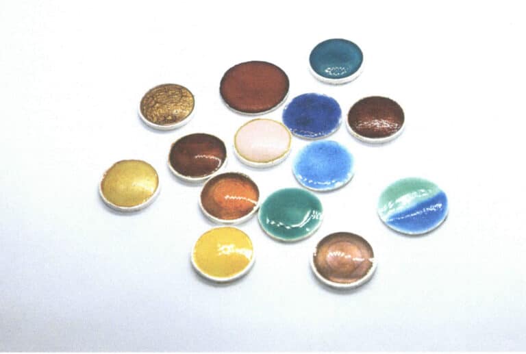
Az ékszerek öntvénygyártásában az ékszeröntvények hatása szorosan kapcsolódik az ékszerötvözet állapotához. Ha a tiszta fémeket és a köztes ötvözeteket közvetlenül keverik és öntik, könnyen keletkezhetnek olyan problémák, mint az egyenetlen összetétel, súlyos veszteség és olyan hibák, mint a lyukak. Ezért általában előkezelni kell az ékszerötvözetet különböző tiszta fémek és ötvözetek gyöngyökbe olvasztásával és öntésével vagy öntvényekbe öntésével, majd a kívánt tömegnek megfelelő arányosításával. Általában az előregyártott gyöngyök módszerét részesítik előnyben, ahol az olvadt fém kifolyik a tégelyből, és a hűtővízbe csepegtetve azonnal lehűl és cseppekre hasad, megszilárdítva a szilárd fémrészecskéket (2-22-2-24. ábra). A kerek és megfelelő méretű ötvözetrészecskék előnyösek az olvadás során az egyenletes összetétel, a hőmérsékletszabályozás és a hibák, például a lyukak, homoklyukak és kemény foltok csökkentése szempontjából, amelyek szintén szorosan kapcsolódnak a fémveszteség szabályozásához.
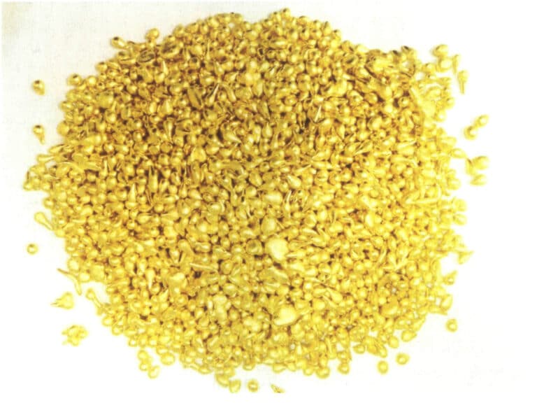
2-22. ábra Sárgaréz részecskék
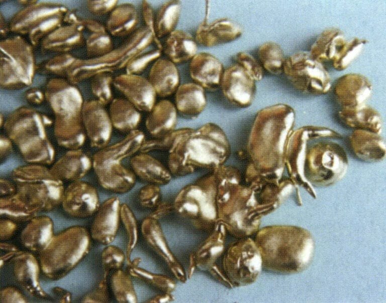
2-23. ábra Cupronickel granulátum
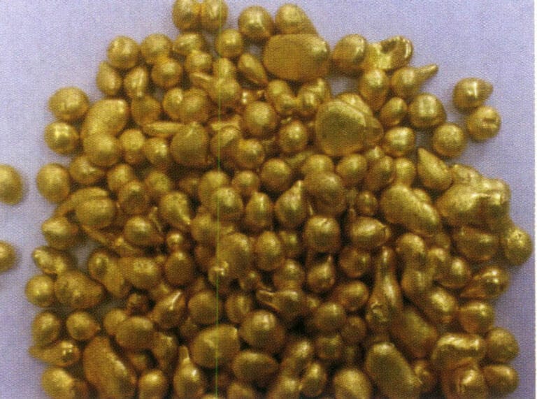
2-24. ábra Bronz részecskék
(2) ötvözet olvasztása
Az ékszerötvözetek közös olvasztási módszerei két fő kategóriába sorolhatók: fáklyás olvasztás és indukciós olvasztás.
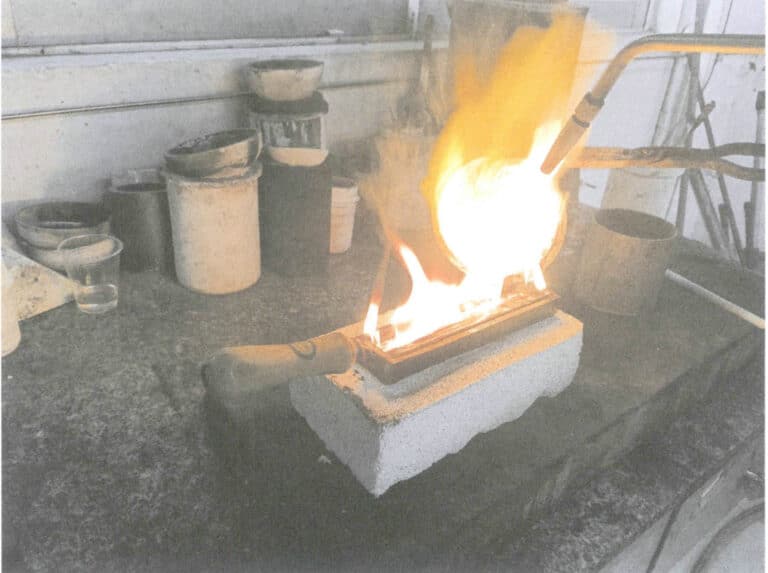
① Fáklyás olvasztás. Az ékszeröntéshez használt fáklyaolvasztás hagyományos gyártási módszer, amely egyszerű eszközöket és berendezéseket használ. Először a fémet lángok segítségével megolvasztják, majd egyszerű öntőberendezéssel kézzel öntik. A fáklyás olvasztás során használt égési gázok közé tartozik a gáz és oxigén, földgáz és oxigén stb. Általában az oxigén-acetilént nem használják, mert annak hőmérséklete túl magas, ami jelentős fémveszteséghez és nehézkes ellenőrzéshez vezet.
A fáklyák olvasztásához általában agyagtégelyeket használnak. Az olvasztás előtt gondosan ellenőrizze a tégely minőségét; a belső falnak sima és sűrű mázas réteggel kell rendelkeznie, salakmaradványok nélkül. Készítsük elő a salakképződéshez a folyósítót, általában vízmentes bóraxot használva. Először melegítse elő a tégelyt, majd adjon hozzá rézrészecskéket, a láng intenzitását és jellegét a megfelelő szintre állítva. Amikor a rézanyag már közel áll az olvadáshoz, szórjon kis mennyiségű bóraxot a folyadék felületére, és egy üvegpálcával óvatosan keverje egyenletesen az olvadt fémet (2-25. ábra). Amikor a hőmérséklet eléri a kívánt öntési hőmérsékletet, a formát ki lehet venni az öntéshez.
Az olvasztási folyamat során ellenőrizze a hőmérsékletet és a láng atmoszféráját; ellenkező esetben súlyos oxidáció következik be, ami fémveszteséghez és az olvadt fém salakszennyezéséhez vezet, különösen a sárgaréz ötvözeteknél, amelyek hajlamosak a jelentős cinkoxidációs veszteségre. Az olvasztási hőmérsékletet általában 980 ~ 1020 ℃ között szabályozzák a fémveszteség csökkentése és az elhúzódó elkerülése érdekében.
2-25. ábra Rézötvözetek fáklyás olvasztása
② Indukciós olvasztás. A rézékszerek gyártása során a rézötvözetek megolvasztására széles körben alkalmazzák az indukciós olvasztási módszert (2-26. ábra). Az olvasztás során a légkör szabályozása jelentősen befolyásolja az olvadt fém minőségét. Általában több módszer létezik, mint például a vákuumolvasztás, a védőgázos olvasztás és a redukáló lángvédős olvasztás. A vákuumolvasztás előnyös a kohászati minőség szempontjából; azonban nem alkalmas rézötvözetek, különösen a magas cinktartalmú sárgarézötvözetek esetében, mert a vákuum súlyosbítja a cink elpárolgását, ami súlyos fémveszteséghez, jelentős összetétel-ingadozáshoz vezet, és az olvadási füst könnyen károsíthatja a vákuumrendszert. Ezért a rézötvözetek indukciós olvasztásakor általában inert gázokat, például argont és nitrogént vagy redukáló lángokat használnak az olvadt fémfelület elkülönítésére és védelmére, hogy kiváló metallurgiai minőséget érjenek el.
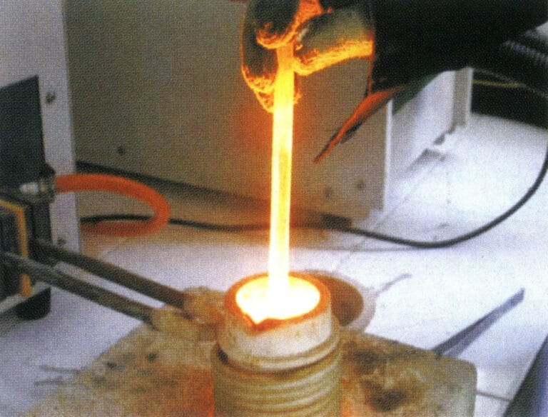
2-26. ábra Rézötvözetek indukciós olvasztása
(3) Öntés
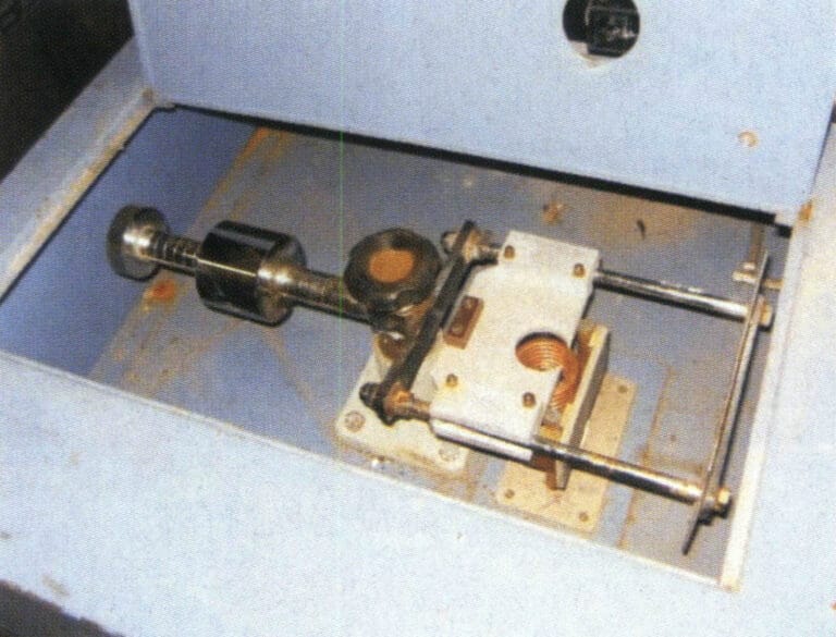
Mivel az ékszerdarabok viszonylag érzékenyek, az öntési folyamat során gyorsan megszilárdulnak, ami a folyékonyság elvesztéséhez vezet. Ezért a hagyományos gravitációs öntés nehezen tudja biztosítani a megfelelő formázást, és szükség van valamilyen külső erő bevezetésére, hogy elősegítsük a formaüreg gyors kitöltését olvadt fémmel, így teljes formájú és világos kontúrokkal rendelkező öntvényeket kapunk. A külső erő alkalmazásának módszere alapján két fő kategóriára osztható: centrifugális öntés és statikus öntés; az öntési folyamat automatizáltsági foka alapján kézi öntőgépekre és nyomásos öntőgépekre osztható.
① Kézi öntés. A kézi öntést általában fáklyás vagy indukciós olvasztással végzik. A fémfolyadék olvasztása és finomítása után a hőmérsékletet az öntési hőmérséklet-tartományba állítják. Ezután a formát kiveszik a kiégető kemencéből, hogy előkészítsék az öntést. Az alkalmazott berendezés típusától függően a kézi öntés főként a centrifugális öntést és a vákuumos szívóöntést foglalja magában.
A 2-27. ábra egy egyszerű mechanikus erőátviteli centrifugális gép néhány kis ékszerfeldolgozó üzemben. Nem rendelkezik indukciós fűtőberendezéssel, nem használ gáz-oxigént a fém megolvasztásához, és nem használ indukciós kemencét a fém megolvasztásához és tégelybe öntéséhez. A gipszformát laposan helyezzük a forgó kar öntőalapjába, és a forgó kart elindítjuk. A centrifugális erő hatására az olvadt fém belép a forma üregébe, és befejeződik az öntési folyamat. A művelet során számos tényező befolyásolja a minőséget, így alkalmas kis ékszerelemek, például láncszemek, fülbevalók stb. öntésére.
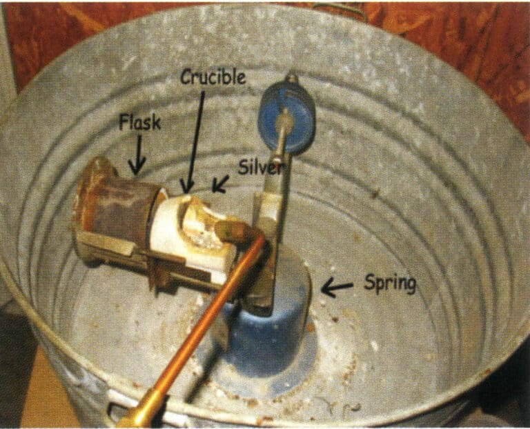
2-27. ábra Egyszerű centrifugális öntőgép Kézi öntés
2-28. ábra Kézi kiöntés a szívógéppel
② Öntőgépek automatikus öntése. Az ékszeripari termékekkel szemben támasztott minőségi követelmények növekedésével és az ékszeripar technológiai fejlődésével az automata öntőgépek nagyon fontos berendezésekké váltak az ékszerek elveszett viaszból történő öntése során, és fontos alapként szolgálnak a termékminőség biztosításához. Az alkalmazott külső erő típusa alapján az általánosan használt ékszeröntő gépek két kategóriába sorolhatók: centrifugális és statikus öntés.
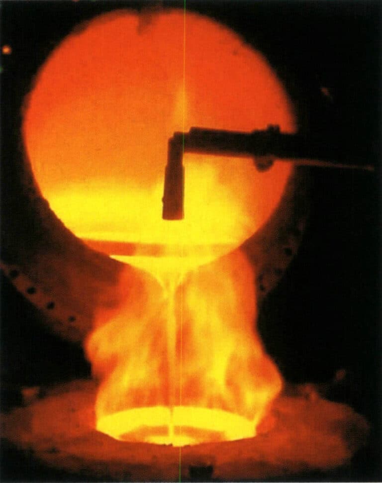
A hagyományos egyszerű centrifugális öntőgépek hiányosságaira válaszul a modern centrifugális öntőgépek integrálják az indukciós fűtést és a centrifugális öntést, jelentős előrelépést érve el a meghajtástechnológia és a programozás terén, javítva a programozási képességeket és a folyamat automatizálásának vezérlését. A 2-29. ábra egy ékszeripari centrifugális öntőgép tipikus olvasztó- és öntőkamráját mutatja, amely rézötvözetből készült ékszerek öntésére használható.
2-29. ábra Centrifugális indukciós öntőgép automatikus öntése
A legfejlettebb és legszélesebb körben használt statikus öntőgép az automata vákuumnyomásos öntőgép (2-30. ábra). Ebből a géptípusból számos modell létezik, és a különböző cégek által gyártott öntőgépek mindegyike sajátos jellemzőkkel rendelkezik. Mégis, általában indukciós fűtésből, vákuumrendszerekből, vezérlőrendszerekből stb. állnak. Szerkezetüket tekintve általában függőlegesek, a felső részük indukciós kamra, az alsó részük pedig vákuumöntő kamra. A tégely alján van egy lyuk, amelyet olvadás közben egy tűzálló dugattyúrúddal zárnak le. Öntéskor a dugattyúrudat felemelik, és az olvadt fémet az öntőüregbe öntik. Általában a dugattyúrúd belsejébe egy hőelemet szerelnek be, amely pontosan tükrözi az olvadt fém hőmérsékletét. Az automatikus vákuumöntő gépek jellemzően vákuum vagy inert gáz atmoszféra alatt olvasztják és öntik a fémeket, csökkentve a fém oxidációjának és a gázfelvételnek a lehetőségét. Ezeket széles körben számítógépes programozással vezérlik, magas fokú automatizálással rendelkeznek, és stabil minőségű öntvényeket állítanak elő, csökkentett porozitási hibákkal, ezért számos gyártó nagyra értékeli őket. Ezt a berendezést kis mennyiségben használják alacsony cinktartalmú rézékszerek öntéséhez, míg a magas cinktartalmú rézötvözetek esetében általában ritkábban alkalmazzák, hogy elkerüljék a vákuumrendszer károsodását.
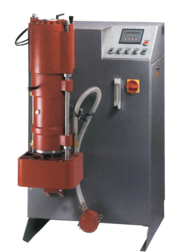
2-30. ábra A vákuumnyomásos öntőgép automatikus öntése
1.7 Öntés tisztítása
Miután az öntvényt kiöntötték, körülbelül 15 percig hagyják állni; ezután a formát vízben leoltják, hogy elvégezzék a robbanó gipsz műveletet. Az öntőpor-forma maradékhője találkozik a hűtővízzel, ami a víz azonnali elpárolgását okozza, ami robbanópor-jelenséget eredményez, amely elválasztja az öntött munkadarabot az öntőpor-formától.
Nagynyomású vízsugárral mossa le a munkadarab felületén maradt öntőport. A kimosott munkadarab általában fekete színű. Áztassa a kimosott öntvényt fluorvizes, kénsavas vagy sósavas vizes oldatban. A savas áztatás alaposan eltávolítja az öntvény különböző részeiről a maradék öntőport és az öntvény felületén lévő oxidált zárványokat. A réz ékszereknek a fluorsavas oldatban történő áztatásakor a koncentráció körülbelül 5%, az áztatási idő pedig körülbelül 20 perc.
Az öntőpor eltávolítása után a munkadarab még mindig fa alakú, és a következő folyamatra való felkészüléshez a nyáknál le kell vágni, osztályozni és típus szerint szét kell válogatni. Először mérje le a fa alakú nyersdarabot az öntőpor eltávolítása után, számítsa ki az öntési folyamat során keletkezett veszteséget, majd végezze el a nyákvágási műveletet.
1.8 Az öntvények utófeldolgozása
Az ékszerek különböző felületi hatásainak eléréséhez és a különböző típusú drágakövek berakásához elengedhetetlen az öntvények utólagos feldolgozása. Ez általában több fő folyamatot foglal magában: mechanikus polírozás, utómunka, foglalat és felületkezelés (pl. polírozás, galvanizálás, színezés stb.). Az alábbiakban röviden bemutatjuk ezeket a fő folyamatokat.
(1) Befejezés
A befejező folyamat az ékszer-alapanyagok integrálása, illesztése, hegesztése és durva felületkezelése, az eredeti modell helyreállítása. A befejező eljárás fontos lépés az ékszerkészítés folyamatában. Az ékszerek minőségét közvetlenül befolyásolja, ha a befejezési folyamatot nem jól végzik el. Az ékszertermékek kategóriái és szerkezeti jellemzői szerint több tipikus típusra oszthatók, mint például gyűrűk, fülbevalók, láncok és karkötők. Kikészítési folyamataik nem azonosak, de általában a következő eljárásokon mennek keresztül.
① Formázás. Állítsa vissza a munkadarabot eredeti modelljére és szabványos méreteire.
② Rögzítse az öntvényt. Először egy durva reszelővel simítsa el a nyákot és a felületet, majd egy sima reszelővel javítsa ki a munkadarab különböző részeit, hogy sima legyen (2-31. ábra).
③ Szerelje össze a hegesztési vagy hegesztési javítási homoklyukakat. Hegessze a szerelvényeket a megfelelő helyre a munkadarabon, amelyek díszítésként szolgálnak vagy rögzítik az összeszerelt munkadarabot (2-32. ábra). Ha a munkadarabon homoklyukak keletkeznek, a javításhoz használjon forrasztóanyagot.
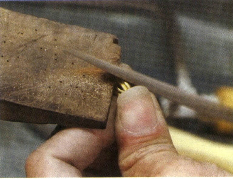
2-31. ábra Vizes öntőcső
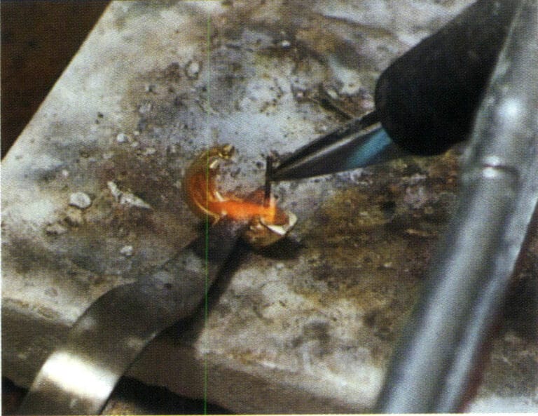
2-32. ábra Összeszerelési hegesztés
④ Forralás timföldes oldatban. Hegesztés után a munkadarab felületén fekete-szürke anyag képződik, amely a munkadarab felületén lévő szennyeződések megtisztítása érdekében alumíniumos vízben való forralás után eltávolítható (2-33. ábra).
⑤ A felület reszelése. Csúszó reszelővel csiszolja le a gyűrű belső körét, külső körét és oldalát, hogy a felület sima és csomómentes, sima alakú legyen.
⑥ Csiszolópapírral történő polírozás. A csiszolópapír eltávolítja a munkadarab reszelőnyomát, így a munkadarab felülete simává válik (2-34. ábra).
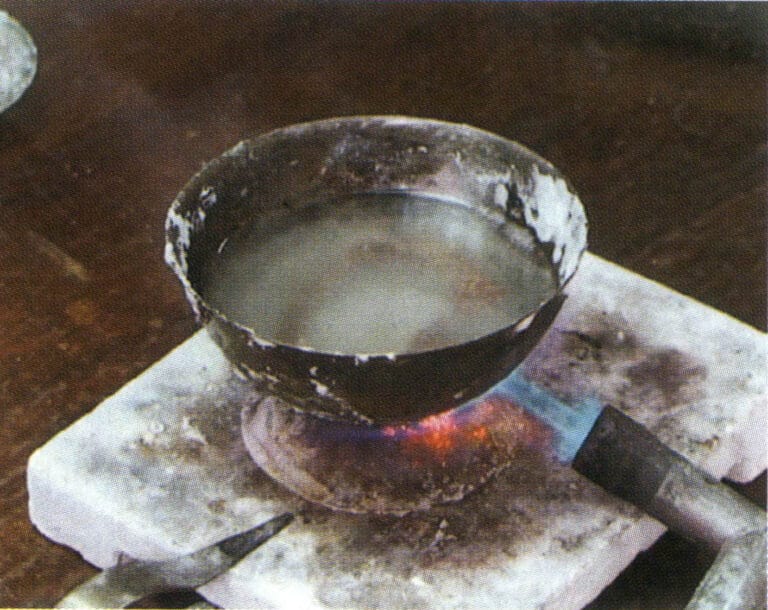
2-33. ábra Forrás alumínium vízben
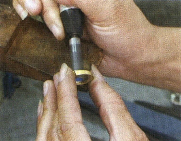
2-34. ábra Csiszolópapírral történő polírozás
(2) Beállított kövek
A foglalási kézművesség olyan technikai módszer, amely különböző színű, formájú és textúrájú drágaköveket kombinál kiterjedt beállítással, reszeléssel, faragással, véséssel és hegesztéssel, hogy különböző formákat és stílusokat hozzon létre, ami magas értéket ad nekik, mint kézműves és dekoratív tárgyak.
A leggyakoribb betétes módszerek közé tartozik az inverz pave foglalat, a szegecses foglalat, a süllyesztett foglalat, az olasz foglalat, a pavé foglalat, a csatorna foglalat és a láthatatlan foglalat. A kőbeállítás teljes folyamata három fő lépésre osztható: a beállítás előtti előkészítés, a beállítási művelet és a beállítás utáni felületkezelés.
① Előkészítő munka a kövek behelyezése előtt. Elsősorban két lépésre oszlik: a kövek kiválasztása és a tűzlakk felvitele.
Kő kiválasztása: Ez magában foglalja a drágakövek különböző specifikációinak minőségének, mennyiségének és súlyának ellenőrzését a megrendelésnek megfelelően, hogy azok megfelelnek-e a követelményeknek. Ezután átvizsgálják és osztályozzák őket, és a drágaköveket az ügyfél megrendelt mennyiségének megfelelően osztják ki a foglalási részlegnek a gyártás megszervezéséhez.
Tűzlakk felhordása: A munkadarabot a tűzlakk fogantyúján rögzíti, megkönnyítve a kezelő számára a kézben tartást és a manipulációt a kőbevonási folyamat során. Leginkább fülbevalókhoz, medálokhoz és más intarziás darabokhoz használják; más intarziás módszerek az áru különleges feldolgozási követelményeitől függnek.
② Beállítási művelet. A beállítási művelet általában öt alapvető lépésre oszlik: a kő pozíciójának mérése, a kő pozíciójának csiszolása, a kő elhelyezése, a kő rögzítése és a javítás. A főbb behelyezési módszerek közé tartozik a szegecses foglalat, a pave foglalat, a csatornafoglalat, a süllyesztett foglalat, a keretbe foglalat, a láthatatlan foglalat stb. A szegecsbeillesztést példaként véve, a műveleti lépéseket a 2-35. ábra mutatja.
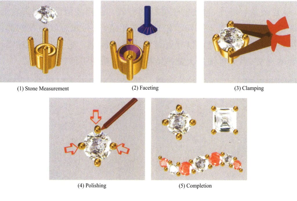
2-35. ábra A tüskék beállítási folyamatának vázlatos ábrája
③ Felületkezelés. Elsősorban három lépésből áll: a tűzlakk lemosása, az élkikészítés és az élkaparás.
A tűzlakk lemosása azt jelenti, hogy a kő berakása után fáklyával megégetik a viaszt a munkadarabon, majd eltávolítják a munkadarabot, és terpentinben áztatják, hogy megtisztítsák a viaszt.
Élkikészítés: A munkadarab érdes felületének simítására szolgáló szerszámok, például reszelők, gépi marók és csiszolópapír használata, a munkadarab felületének sima és puha állapotba hozása a kőbeállítás után.
Szélek vágása: Ez a folyamat a munkadarab aranyélének belső oldalán lévő marások kiegyenlítése a keretbeállítás, a csatorna beállítása és a süllyesztett beállítás után, a belső élvonalak simává és a felület fényessé tétele.
(3) Felületkezelés
A rézötvözetből készült ékszerek felületkezelésére számos módszer létezik, és a galvanizálás az egyik leggyakrabban használt felületkezelési módszer. Általában három fő szakaszból áll: előkezelés, galvanizálás és utókezelés.
① Előfeldolgozás. A polírozás kulcsfontosságú folyamat az ékszerek legjobb megjelenésének eléréséhez. A leggyakrabban használt berendezések közé tartoznak a közönséges polírozógépek és a tárcsás polírozógépek, a közönséges polírozógépek két típusa: egyszerű és újrahasznosító. Amikor a polírozókorong nagy sebességgel forog, magas hőmérséklet keletkezik az ékszer, a polírozókorong és az olvadt polírozószer között, ami fokozza a fém plaszticitását, javítja a felület finom egyenetlenségeit és növeli az ékszer fényességét (2-36. ábra). A polírozás hatása elsősorban a megmunkálandó felület jellemzőitől, azaz a munkadarab felületének polírozási és szintezési fokától, valamint a polírozás során használt polírozóanyagok típusától és jellemzőitől függ. A polírozott ékszereknek sima, hibátlan felületet, szimmetrikus formákat, sima vonalakat, egyenletes vastagságot, lekerekített éleket és sarkokat kell elérni, és mentesnek kell lenniük az olyan problémáktól, mint a törött tüskék vagy a meglazult kövek.
A polírozott ékszerek felületén szinte elkerülhetetlenül megtapadnak a viasz- vagy olajfoltok, és a galvanizálás előtt zsírtalanító kezelésnek kell alávetni. A szokásos zsírtalanítási módszerek közé tartozik az ultrahangos zsírtalanítás és az elektrokémiai zsírtalanítás. Az ultrahangos zsírtalanítás tovább fokozhatja az oldószeres és kémiai zsírtalanítás sebességét és hatékonyságát, minimális korrózióval jár a hordozón, és magas zsírtalanítási és tisztítási hatékonyságot kínál, így különösen hatékony a finom lyukakkal és vakfuratokkal rendelkező összetett munkadarabok esetében. Az ultrahangos tisztítógépek az ékszerkészítésben nélkülözhetetlen berendezéssé váltak (2-37. ábra). A múltban a holt sarkok, vakfuratok és nehezen hozzáférhető területek tisztítása nehéz problémát jelentett, de az ultrahangos tisztítás hatékonyan megoldja ezt a problémát. Ez különösen fontos az ékszerek esetében, mivel a legtöbb darab összetett és finom szerkezetű munkadarab.
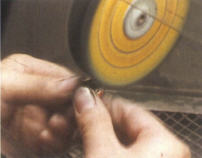
2-36. ábra Ruhás kerék polírozás
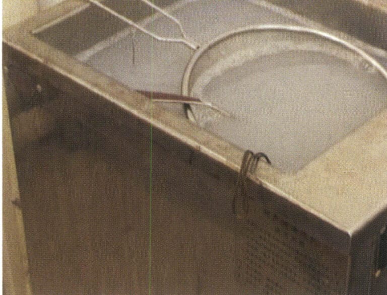
2-37. ábra Ultrahangos zsíreltávolítás
Az elektrokémiai zsírtalanítás során az ékszereket lúgos elektrolit katódjára vagy anódjára függesztik (2-38. ábra). Az elektrolízis során az ékszer felületéről kiszabaduló buborékok erős szakító hatást gyakorolnak a felületen lévő zsírrétegre, és a felszálló buborékok által okozott keveredés folyamatosan elviszi az olajat, tovább fokozva a zsírtalanító hatást. Az elektrokémiai zsírtalanítás sebessége meghaladja a kémiai zsírtalanítás sebességét, ami jó hatékonyságot eredményez.
Az ékszereket meg kell tisztítani és gyengén maratni kell, mielőtt a galvanizáló tartályba kerülnének. A tisztítás célja, hogy eltávolítsa az ékszer felületén megtapadt folyadékot, elősegítse a fémionok lerakódását, és elkerülje a galvanizáló oldat szennyeződését. A réz ékszereket a galvanizálás előtt általában többlépcsős ellenáramú tisztító gyártósorral tisztítják, ahogyan az a 2-39. ábrán látható. A maratás fő célja a munkadarab felületén esetlegesen visszamaradt lúgos oldat semlegesítése, a munkadarab felületén lévő oxidfilm feloldása és a felület aktiválása a galvanizáló réteg és az alapfém közötti erős kötés biztosítása érdekében. A maróoldat koncentrációja általában meglehetősen híg, 1%~5%, és nem károsítja az anyag felületét, az idő általában csak néhány másodperctől 1 percig tart.
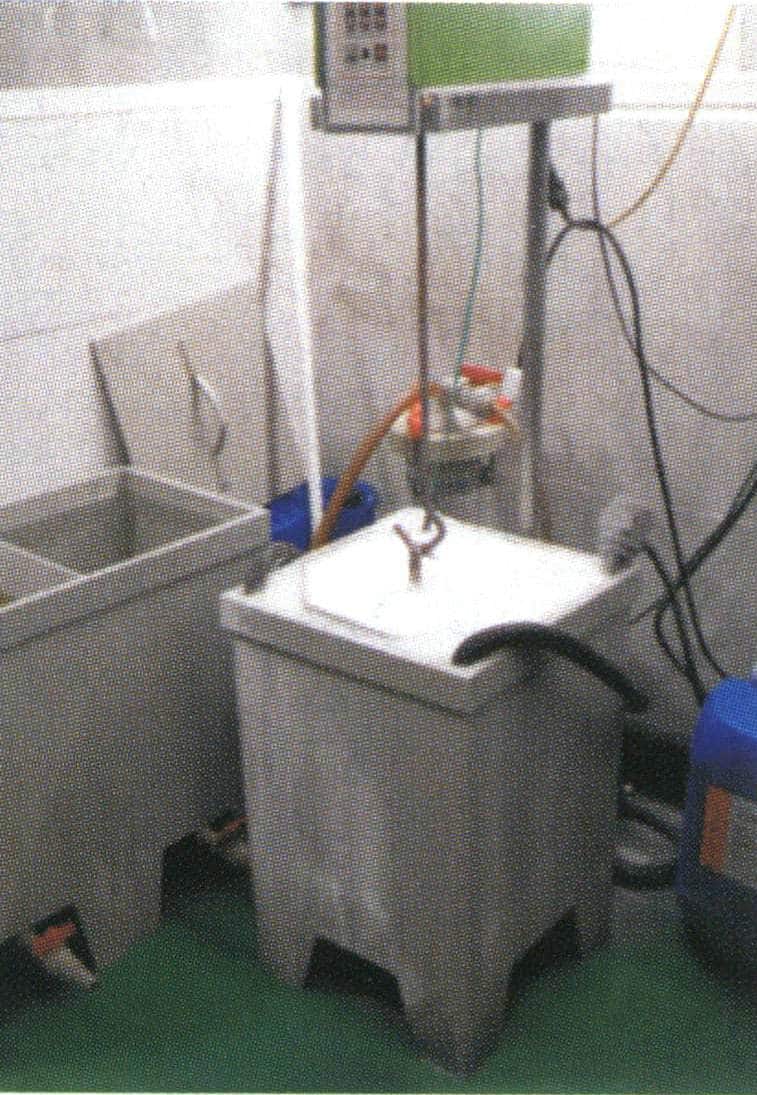
2-38. ábra Elektromos olajmentesítés
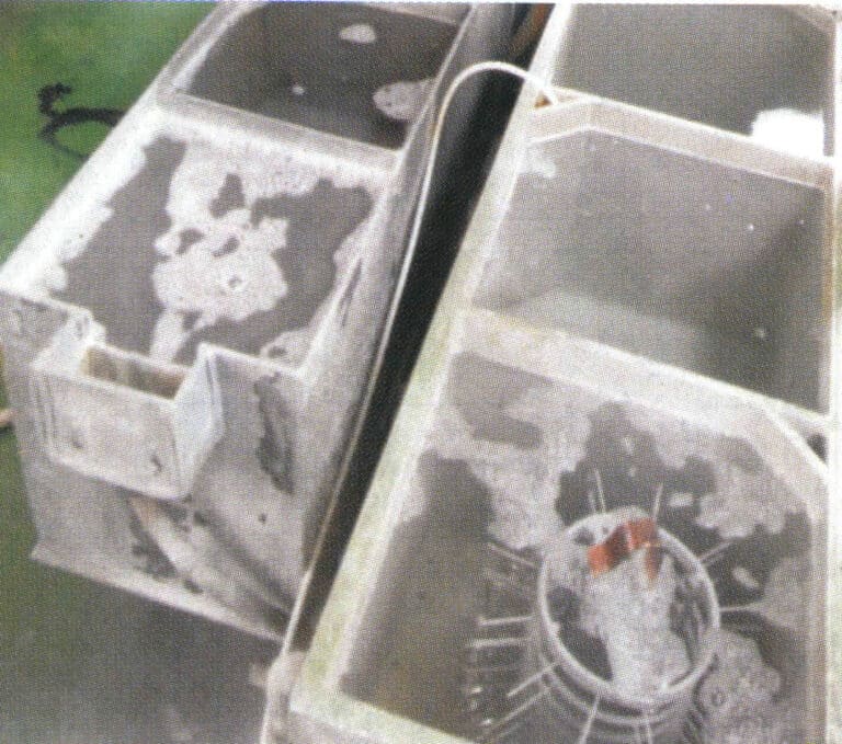
2-39. ábra Előzetes galvanizálás előtti tisztítás
② Galvanizálási művelet. A réz ékszerek felületi galvanizálása általában többféle módszert foglal magában, mint például az ezüstözést, az aranyozást és a ródiumozást. Aranyozás vagy ródiumozás esetén az ékszer felületére általában előzetesen egy nikkelréteget visznek fel. A gyártás során rendszeresen ellenőrizni kell a galvanizáló oldatot a galvanizáló tartályban és a különböző kulcsfontosságú anyagmutatókat, hogy megelőzzük a mutatók eltéréseit, amelyek a termék minőségével kapcsolatos problémákhoz vezethetnek.
③ Galvanizálás utáni kezelés. A munkadarabot galvanizálás után először egy galvanizáló oldat visszanyerő csészébe mártják, vízzel öblítik, forró tiszta vízben áztatják, majd gőzmosó géppel öblítik, és végül forró légpisztollyal szárítják.
2. A réz ékszerek bélyegzési folyamata
A bélyegzési eljárást széles körben használják a réz ékszerek gyártásánál, különösen a fehér ékszereknél, amelyek többsége a bélyegzési eljárást használja. Az eljárás nagyon hasonlít a rozsdamentes acélból készült bélyegzett ékszerekéhez; a részletekért lásd a bevezetést más cikkekben.
3. A réz ékszerek elektroformázási folyamata
3.1 Bevezetés az elektroformázási technológiába
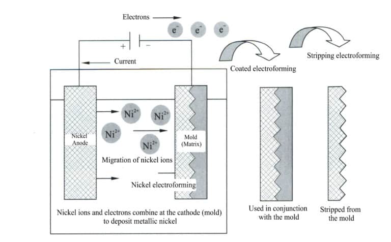
2-40. ábra Elektroformázás vázlatrajza
Használja a kívánt alakban készült eredeti formát katódként, az elektroformázó anyagot pedig anódként, és helyezze őket együtt az anódanyaggal megegyező fémsóoldatba, egyenáramot alkalmazva. Az elektrolízis hatására a fém elektroformáló réteg fokozatosan lerakódik az eredeti öntőforma felületére, és eléri a kívánt vastagságot, eltávolítják az oldatból, és az elektroformáló réteg elválik az eredeti öntőformától, így az eredeti öntőforma alakjának megfelelő fémutánzatot kapunk.
Az elveszett viaszöntési eljárással összehasonlítva a galvanoformálással nagyobb méretű, nagyon vékony falú munkadarabokat lehet előállítani, így különösen alkalmas díszítőelemek készítésére. A galvanoformázás fő hátránya az alacsony hatékonyság, a galvanizált fémréteg vastagsága általában 0,02~0,05 mm óránként. Nagy koncentrációjú elektroformáló oldat megfelelő használatával, az oldat hőmérsékletének növelésével és a keverés fokozásával javítható az áramsűrűség, csökkenthető az elektroformálási idő és ezáltal növelhető az elektroformálás hatékonysága.
3.2 Réz ékszerek elektroformázási folyamata
A réz ékszerek tipikus elektroformázási folyamata magában foglalja a penész megformálását, a penész megismétlését, a viaszforma befecskendezését, a viaszforma befejezését, az ezüstlemez alkalmazását, az elektroformázást, a befejezést, a viasz eltávolítását és a polírozást.
(1) viaszforma készítés
A viaszformák készítése magában foglalja a viaszanyag megtervezését, a forma megformálását, a forma másolását, a viaszformák befecskendezését és a viaszformák befejezését. Nagyméretű munkadarabok készítésekor agyagból faragott sablonokat is használnak, amelyeket szilikon- és viaszformákba másolnak.
① A viaszforma megformálása. Viaszsablonba vésve, magas domborzatú, mély domborzatú, áttört és vonalas faragási technikával. Először a kezdeti durva faragást végzik, amelyet a tervezési szándéknak és a folyamat feltételeinek megfelelően végeznek, faragószerszámok segítségével a viaszanyagot egy bizonyos formára alakítják, hogy meghatározzák annak alapformáját; a kezdeti durva folyamat után a finom faragást és a részletes befejezést végzik az előző lépések különböző hiányosságainak kiküszöbölésére, valamint a viaszforma felületének simává és polírozottá tételére.
② Replikáló formák. Másolja a minősített faragott viaszmodellt egy gumiformába a tömeggyártás céljának elérése érdekében.
Kis réz ékszerek esetén először rögzítse a viaszmodellt egy üvegfelületre, vegye körül csiszolópapírral, hagyva egy bizonyos távolságot a modell és a csiszolópapírcső között, majd vákuumozza az egyenletesen összekevert szilikont és injektálja a csiszolópapírcsőbe (2-41. ábra), majd vákuumozza, és a ragasztót a tényleges helyzetnek megfelelően injektálja. Miután feltöltötte szilikonnal, kérjük, helyezze a vákuumgépbe a vákuumozáshoz, és az utoljára vákuumozott csiszolópapírcsövet tegye megfelelő és stabil helyre, hogy hagyja természetesen megszáradni.
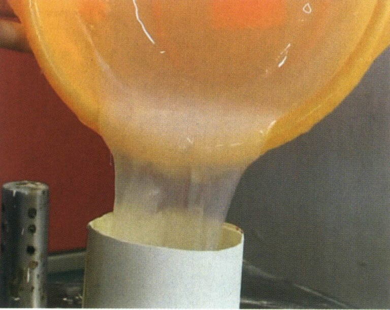
2-41. ábra Gumiminták sokszorosítása
A nagyméretű rézdíszek esetében általában azt a módszert alkalmazzák, hogy először ragasztót visznek fel a sablonra, majd gipszet használnak a másoláshoz. Rögzítse a modellt egy tárcsára, és ecsettel vigye fel az előkészített szilikont a sablonra. Az első réteg minősítése után ismételje meg az ecsetelést még kétszer, amíg a vastagság el nem éri a 3~5 mm-t. A nagyobb homorú lyuk kitöltéséhez használja az olajos agyagot. Ezután a megfelelő mennyiségű vízzel keverjen egy jó gipszmasszát, lapos lapáttal és kézzel (gumikesztyűt viselve) kaparja és törölje a gipszsárat a formalapra, vastagsága kb. 20 ~ 30 mm. Kaparás és törlés, attól függően, hogy a modell alakjának összetettsége, több részre bontják a gyártás, két részre osztva, komplexen 3 ~ 4 vagy több darabra osztva, hogy megkönnyítsék a gumiforma és a modell eltávolítását. A munka után az egész formát természetes módon száradni helyezzük, gumikalapáccsal kopogtatjuk a lebomlott gipszréteget.
③ Formavágás. Szikével vágja le a szilikonréteget a megfelelő helyen, és távolítsa el a modellt. A forma vágásakor olyan területeket válasszon, amelyek könnyen javíthatók, hogy az öntött viaszformát könnyű legyen befejezni (lekaparni) a lemezen. Kerülje az ember- vagy állatszobrok arcvonásainak átvágását. A forma kivágása után ellenőrizze a szilikonforma minőségét, hogy vannak-e buborékok, és hogy a szilikonformák szorosan illeszkednek-e egymáshoz. Nagyméretű dísztárgyak esetén zárja le a kivágott szilikonformát, a szilikonformát gipsszel bontva tartsa össze, rögzítse, majd ragasztóvonalakkal és ragasztószalaggal rögzítse szorosan.
④ Viaszformák befecskendezése. A gumiszerszám belsejében lévő szennyeződéseket fújja el a légkompresszor gázával, majd helyezze a formát egy elektromos sütőbe, hogy előmelegítse körülbelül 5 percig, így a forma hőmérséklete elérheti a 60 ~ 65 ℃-ot, és eltávolíthatja a nedvességet. Vegye ki a formát a sütőből, zárja le, és győződjön meg arról, hogy az illesztések teljesen lezárultak, és rögzítse őket gumiszalaggal. Egy vaskanállal kanalazzuk ki a viaszt az elektromos fűtőtartályból, és öntsük a gumiszerszámba (2-42. ábra), majd tegyük be egy vákuum-vibrátoros gépbe, hogy 1~2 percig vákuumozzuk, távolítsuk el a viaszkiegészítőt, és ismét vákuumozzuk 1~2 percig. A befecskendezés, a kiegészítés és a vákuumozás befejezése után helyezze a gumiformát a munkaasztalra, hogy természetes módon lehűljön. Miután az öntőnyílás megszilárdult, állítsa a formát egy hideg vízzel töltött műanyag medencébe, hogy felgyorsítsa a viasz megszilárdulását. A megszilárdulási idő a viasz mennyiségétől függ, általában több mint 30 perc, de néha akár 1 nap is lehet. Miután a gumiszerű forma belsejében lévő viaszmodell teljesen megszilárdult, lazítsa meg a gumiszalagokat és a ragasztószalagot, és nyissa ki a gumiszerű formát a viaszfigura eltávolításához.
⑤ Viaszformák kikészítése. Használjon viaszkaparót vagy sebészkést, hogy eltávolítsa a viaszformáról a villanásnyomokat, viasznyomokat, spricceket stb. (2-43. ábra), és a viaszforma teljes felületét szép és sima legyen. Használjon elektromos forrasztópákát, hogy viasszal pöttyözze ki a viaszformán lévő apró lyukakat és egyéb hibákat, vagy kössön össze több viaszrészt. Törölje át a viaszforma felületét benzinnel, hogy tiszta és sima legyen.
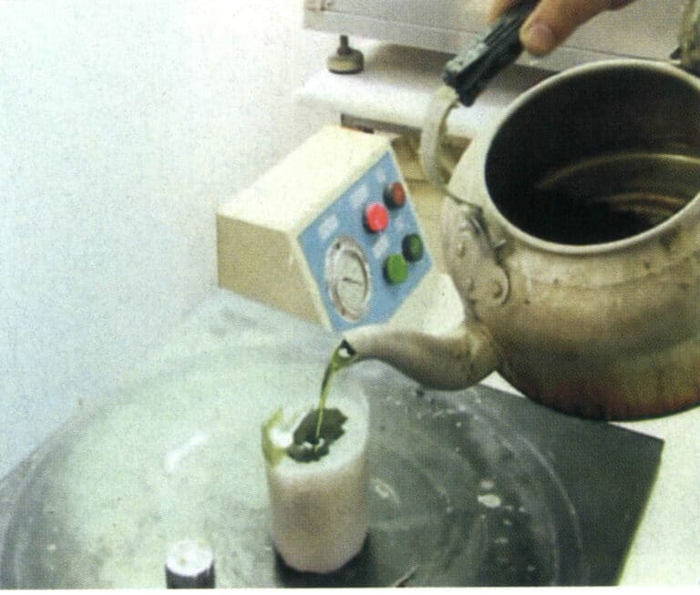
2-42. ábra Viaszformába történő befecskendezés
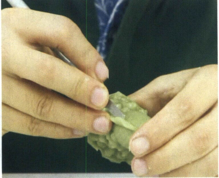
2-43. ábra Viaszformák kikészítése
(2) Elektroformázás
Az üreges elektroformálás a viaszformán alapuló, ezüstlemez bevonattal és elektroformázási technológiával készült üreges elektroformázási ékszerdarabok folyamata. A nagyobb méretű és különleges igényű darabok esetében a felületkezeléshez galvanizálás is szükséges.
① Helyezze be a függesztőrudakat. Az öntvénytartály elektroformálásának megkönnyítése, valamint a rögzítés és a vezetőképesség elérése érdekében a viaszformába függesztett rudakat kell behelyezni.
② Vigyen fel ezüstlemezt (vezető réteg). Mivel a viaszforma nem vezető anyag, a viaszforma felületére egyenletes ezüstlemezréteget kell felvinni. Az ezüstlemez természetes száradási folyamata során az oldószerben lévő aceton elpárolog, és a viaszforma felületén egy nagyon vékony vezető réteg képződik, így előkészítve a galvanizálás folyamatát (2-44. ábra).
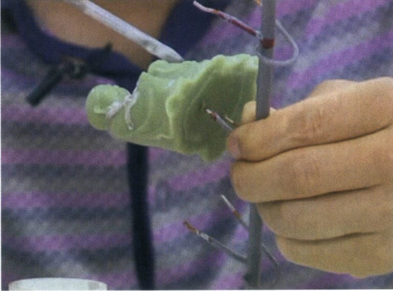
2-44. ábra Ezüstlemez bevonat
③ Nyissa ki a fenntartott lyukakat. A viasz és az ezüstlemez eltávolítása és a fém tisztaságának biztosítása érdekében a díszben lévő fémnek az utólagos feldolgozásra fenntartott lyukakat kell hagyni. Ezzel elkerülhető a fémveszteség növekedése és a termékhulladék valószínűsége a késztermékben lévő lyukak megnyitása miatt. A fenntartott lyukak megnyitásának két szempontot kell követnie: először is, nem befolyásolhatja az esztétikát, és viszonylag rejtett helyre kell helyezni; másodszor, a mennyiségnek és a méretnek megfelelőnek kell lennie. Ezért ezt össze kell hangolni a különböző folyamatokkal, például a viaszfaragással, a karakterek gravírozásával, a rudak behelyezésével és az utófeldolgozással, és nem lehet önállóan elvégezni.
④ Mérés. Helyezze a viaszformát a vasból készült függesztőrúddal együtt az elektronikus mérlegre, hogy megértse és ellenőrizze az öntvény súlyát.
⑤ Helyezze a formát a tartályba az elektroformázáshoz. A viaszformát a tartályba helyezés előtt tiszta vízzel meg kell tisztítani, hogy a felületről eltávolítsuk a port; ellenkező esetben az öntvényen a por miatt perforációk keletkezhetnek. A viaszformában több mélyedéssel rendelkező területeknek az öntőhenger fémhálója felé kell nézniük, ami gyorsabb kiöntési sebességet biztosít a mélyedésekben és egyenletesebb öntőréteget. Ellenkező esetben az öntési sebesség a mélyedésekben lassú lesz, ami a formázás után vékony öntőréteget eredményez, ami a csiszolás és a viasz eltávolítása során perforációhoz vezethet.
A várható kezdési időpontban vegye ki az öntvényt mérlegelésre. Ha a súly megfelel az előírt tartománynak, akkor elindítható és megtisztítható, majd az öntvényből a lógó rúd regisztrálható és átadható a következő technológiai műveletnek.
(3) Felületkezelés
A rézből galvanizált alkatrészek felületén általában aranyozásra van szükség. A plüsshomok termékek esetében általában közvetlenül a réz elektrokémiai formázása után egy vékony aranyréteggel vonják be. Az aranyozás a rézből galvanizált alkatrészek felületkezelése után történik a víz és a termékek esetében. A tipikus felületkezelési feladatok közé tartozik a befejezés, a fúrás, a viasz eltávolítása, a polírozás és az aranyozás.
① Befejezés. Végezze el az öntött felület előzetes kezelését a görcsök eltávolítása érdekében.
② Viasz eltávolítása. Vegye ki a viaszt az öntvény belsejéből, hogy az öntvény egy teljes fémtest, egy üreges, többrétegű ékszeripari öntvény legyen.
Először tegye az ékszereket a 150~300 ℃-os elektromos sütőbe 20~30 percre, hogy kiégesse a viaszt az ékszerből. Vegye ki, amíg forró, és helyezze be az ultrahangos viaszeltávolító gépbe, hogy eltávolítsa a maradék viaszt. A viasz eltávolítása után vegye ki az ékszert, és öntse bele a vizet, majd helyezze az öntvényt az ultrahangos tisztítógépbe a tisztításhoz. Öblítse le az öntvény felületét csapvízzel, fújja el a vízcseppeket egy légpisztollyal az öntvény belsejéből és külsejéből, és hagyja, hogy a levegőn természetesen megszáradjon a munkapadon.
③ Sütés a sütőben. A tartozék felületének tisztítása után kérjük, helyezze a 750 ℃-os sütőbe körülbelül 10 ~ 20 percig sütni fokon, hogy eltávolítsa a nedvességet és a szennyeződéseket a homokban, megakadályozza a piros foltok megjelenését, megszünteti a belső feszültséget, és megváltoztatja a tartozék törékenységét.
④ Polírozás. Az öntvények bizonyos területeinek polírozása, hogy a termék feltűnőbbnek, káprázatosabbnak és nemesebbnek tűnjön.
⑤ Aranyozás. A fő cél a munkadarab felületvédelmének fokozása és a munkadarab felületének elszíneződésének megakadályozása. A munkadarabot kémiai zsírtalanítóba helyezik, és egy elektro-zsírtalanító tartályban tisztítják a felületi olaj eltávolítása érdekében. A tisztítás után a vízzel történő tisztítás után kerül sor az aranyozási műveletre.