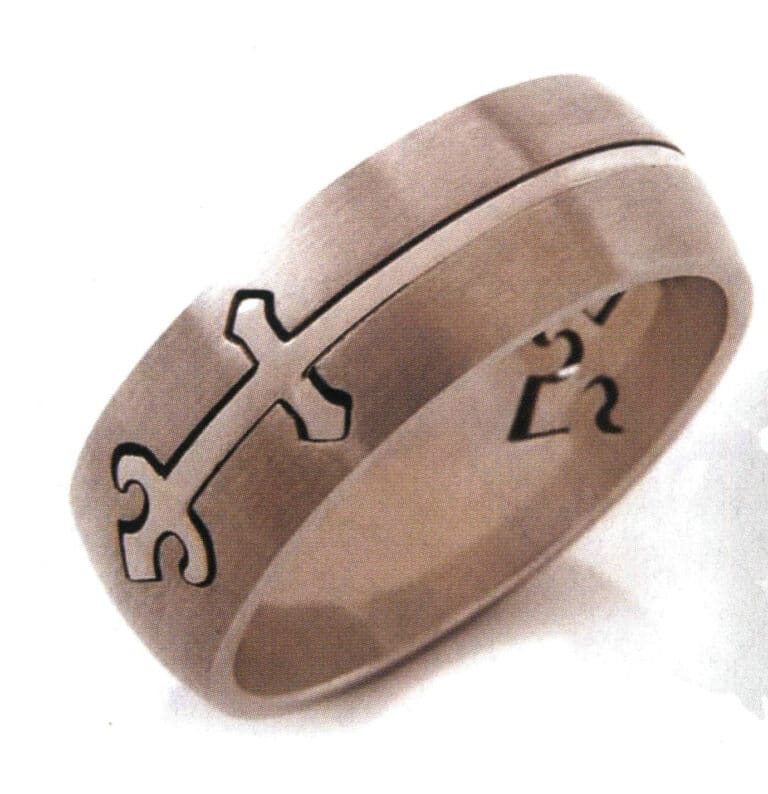
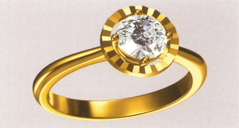
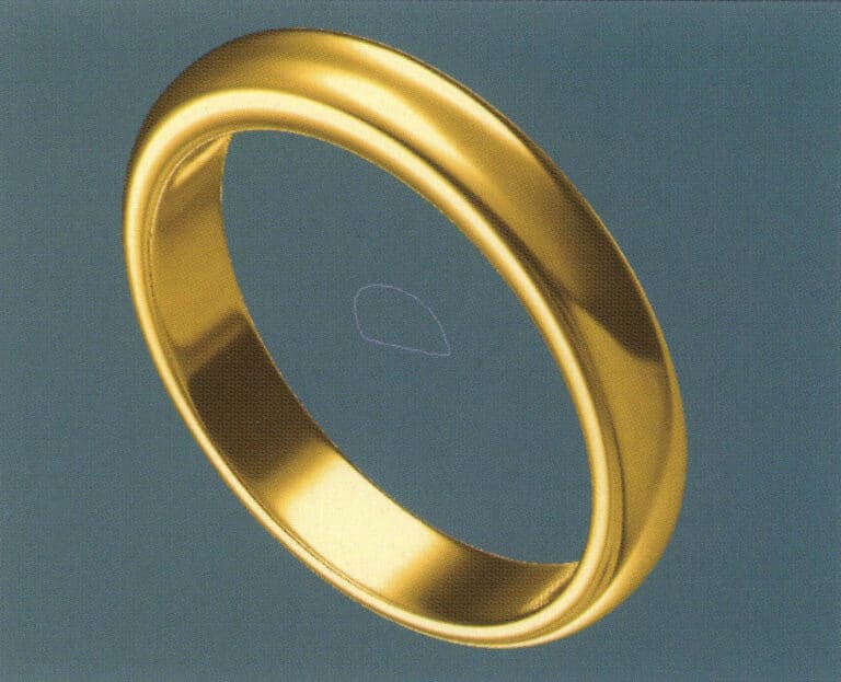
Anillo con engaste de diamantes
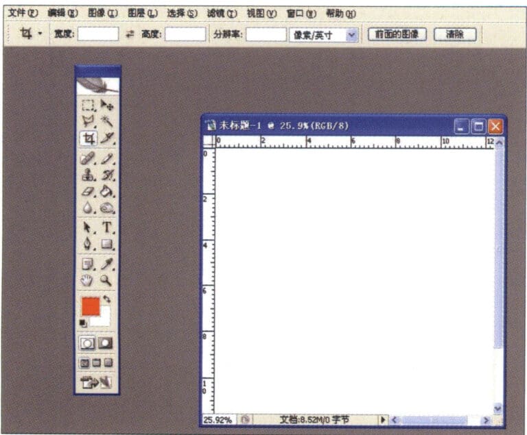
1. Crear un nuevo archivo en Photoshop con una resolución de 300 píxeles/pulgada.
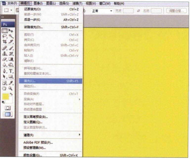
2. Select "Edit" > "Fill" from the menu bar, and set the foreground color to yellow

3. Select "Filter" from the menu bar > "Mottled" > "Add Mottled"
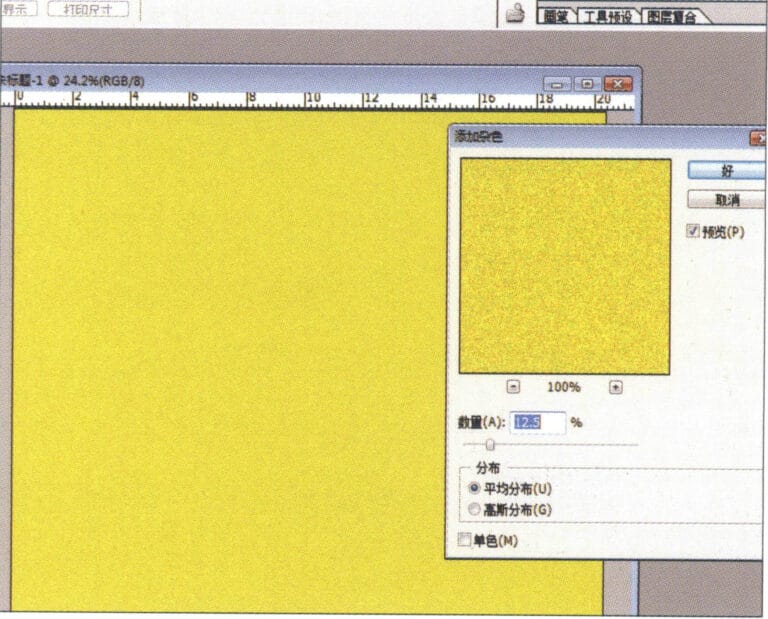
4. Entre en el cuadro de diálogo "Añadir moteado", introduzca los valores correspondientes y confirme
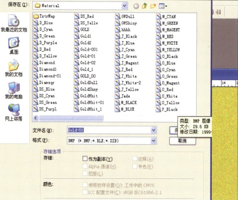
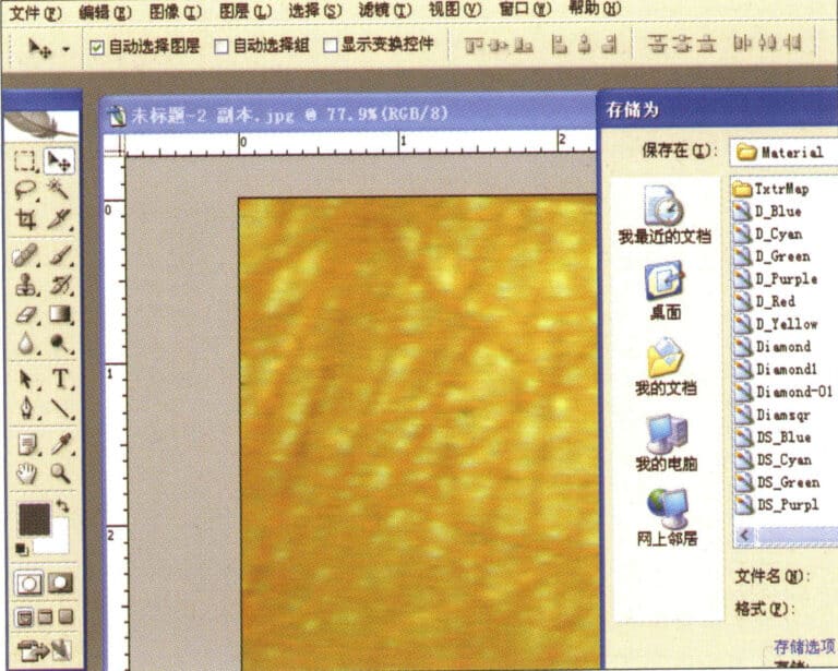
5. Store the document in the "JewelCAD" > "Material" folder, saved in "BMP" format

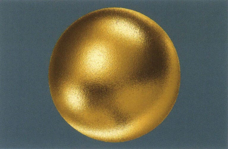
6. Create a new file in JewelCAD, select "Surface" > "Spherical Surface" from the menu bar
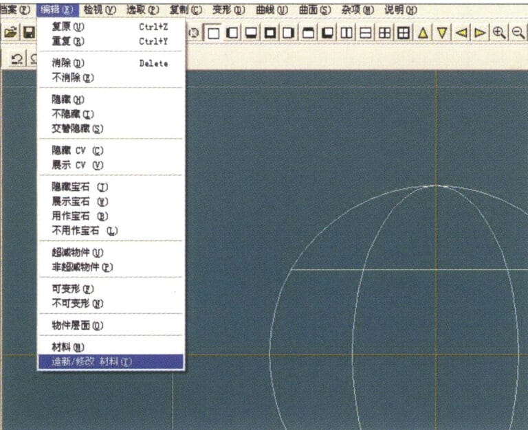
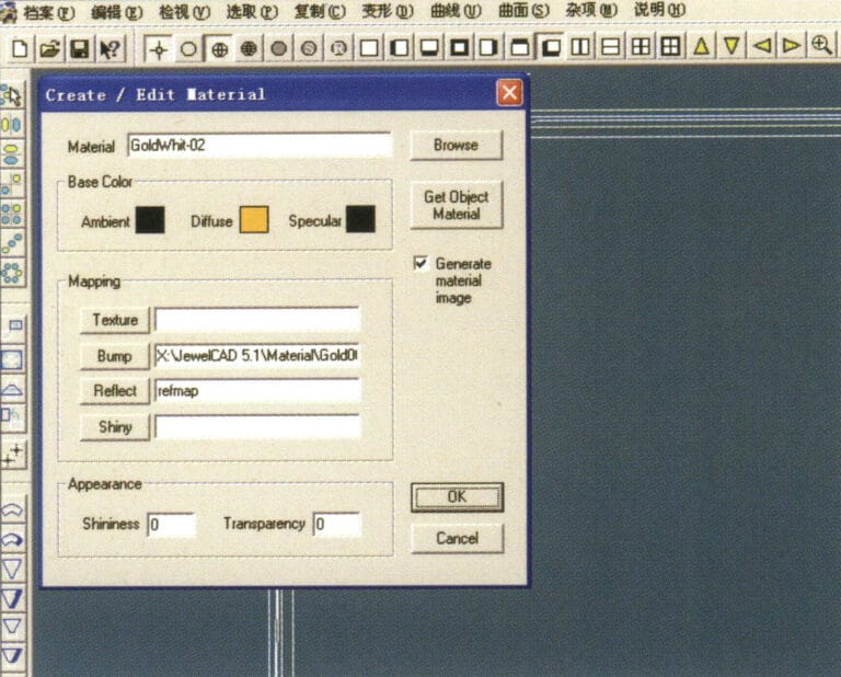
7. Select "Edit" > "Create/Modify Material" from the menu bar
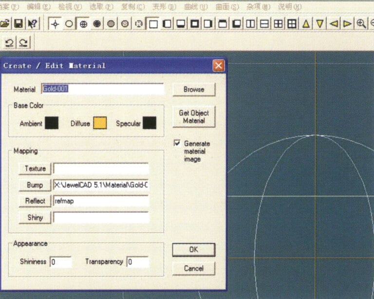
8. Acceda al cuadro de diálogo "Crear/Modificar material", introduzca los valores correspondientes y confirme
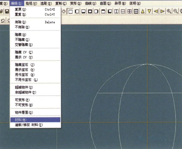
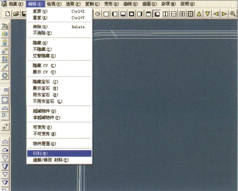
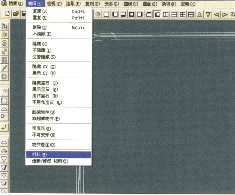
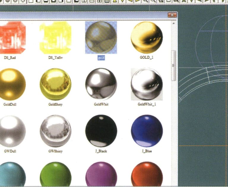
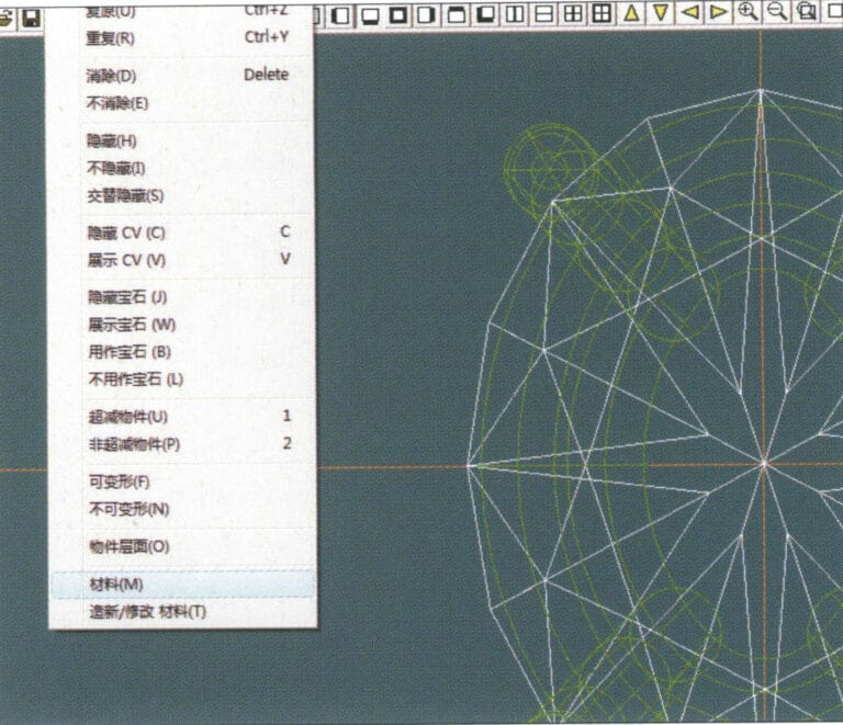
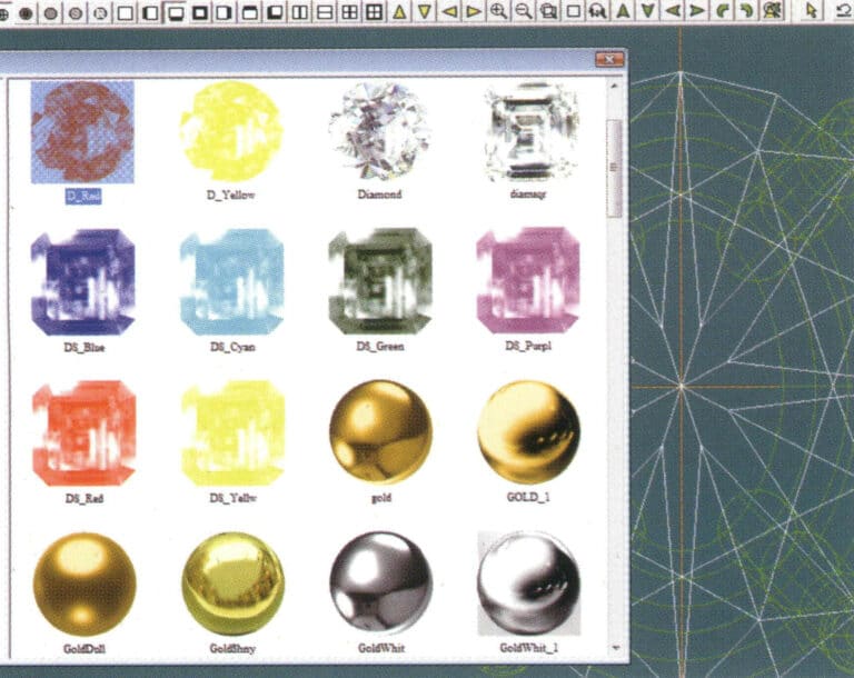
9. Select "Edit" > "Materials" from the menu bar
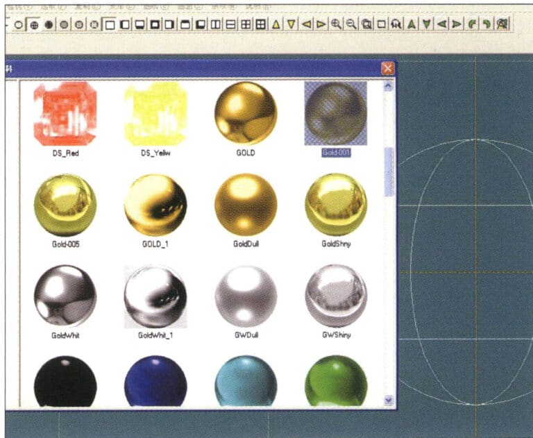
10. Entre en el cuadro de diálogo "Materiales", seleccione el material y confirme
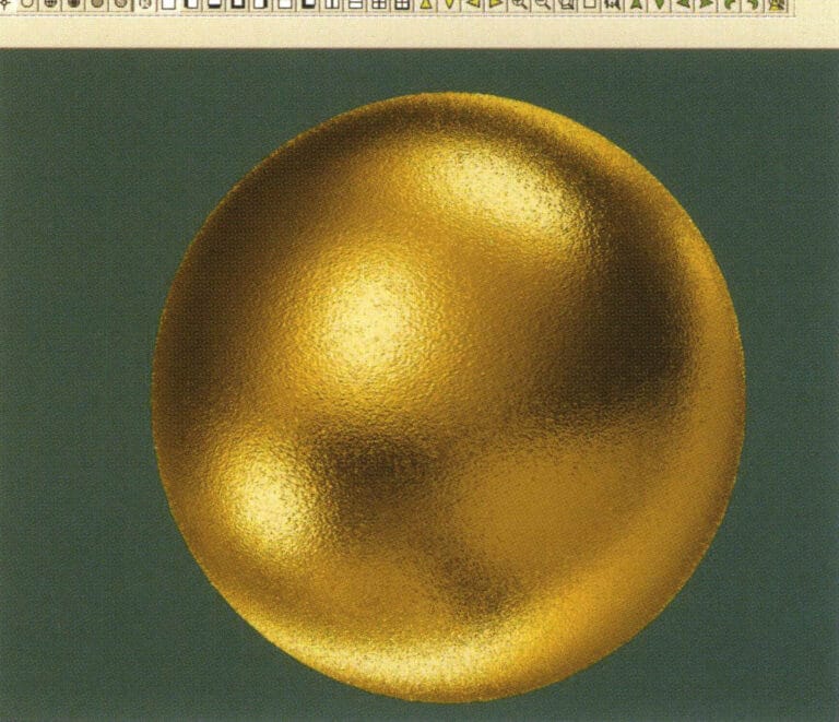
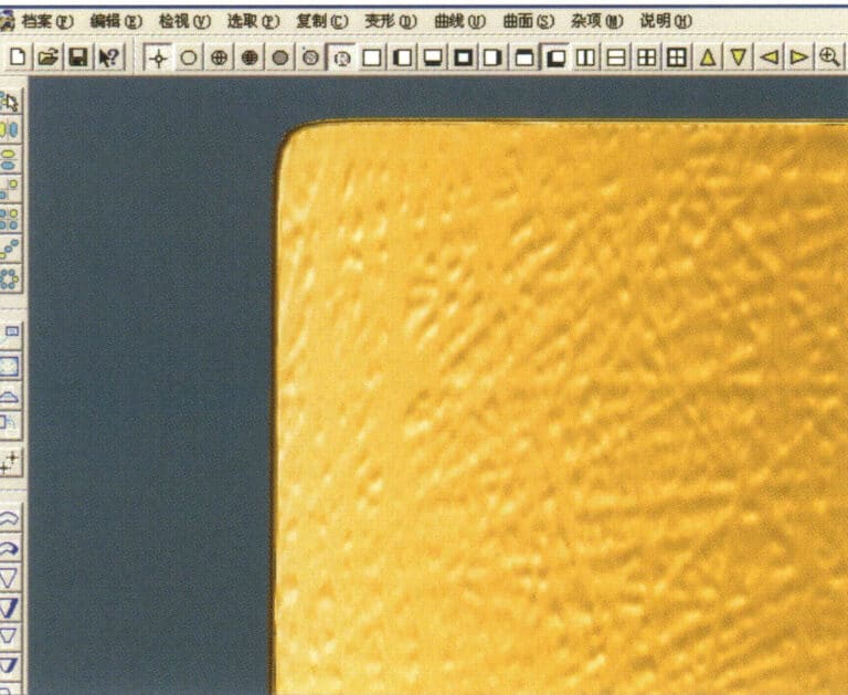
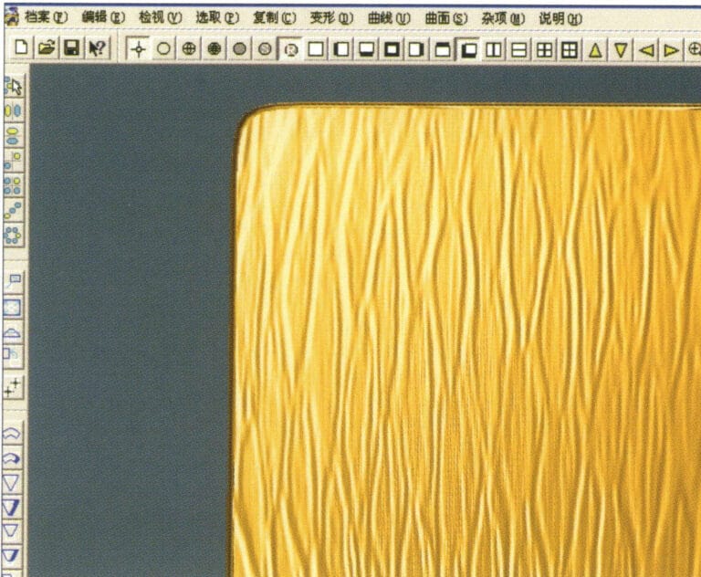
11. Select "View" > "Shadow Map" from the menu bar to inspect the shadow effects.
12. Select "File" > "Save File" from the menu bar to save the document
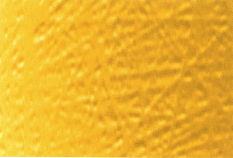

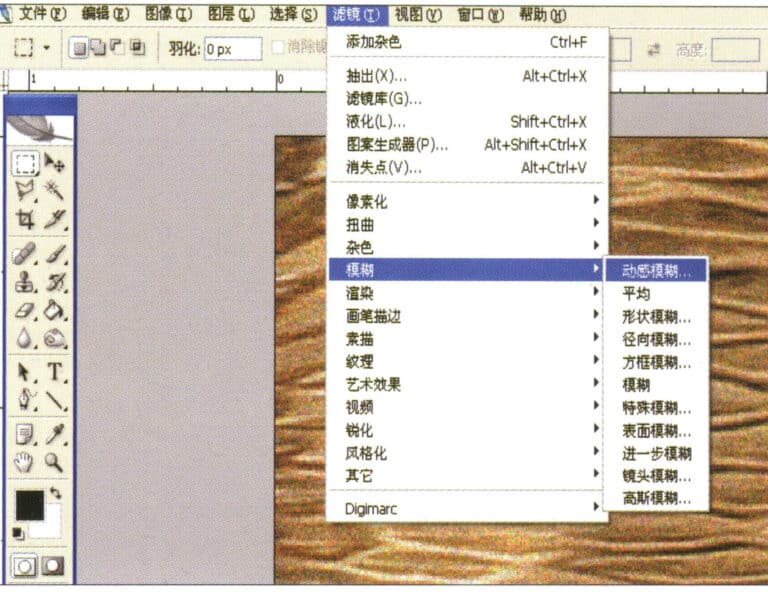
1. Scan a texture file in Photoshop with a resolution of 300 pixels/inch, and select "Filter" > "Blur" > "Motion Blur" from the menu bar to apply the blur effect
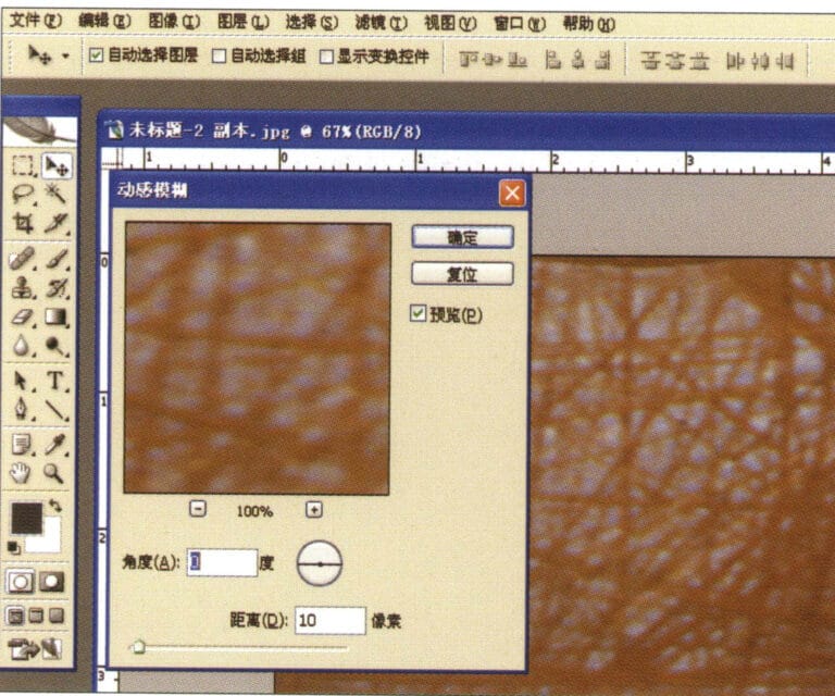
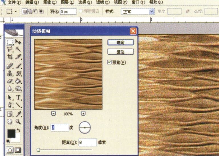
2. Acceda al cuadro de diálogo "Desenfoque de movimiento", introduzca los valores correspondientes y confirme
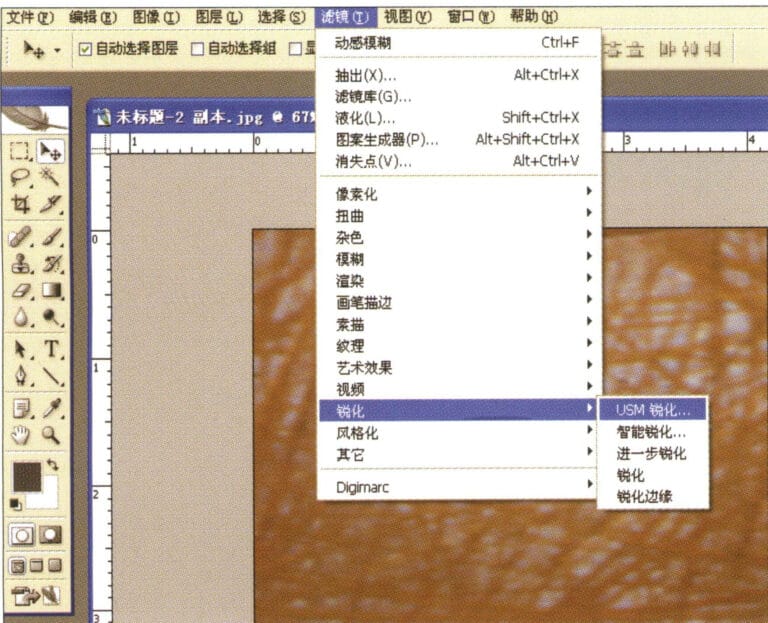
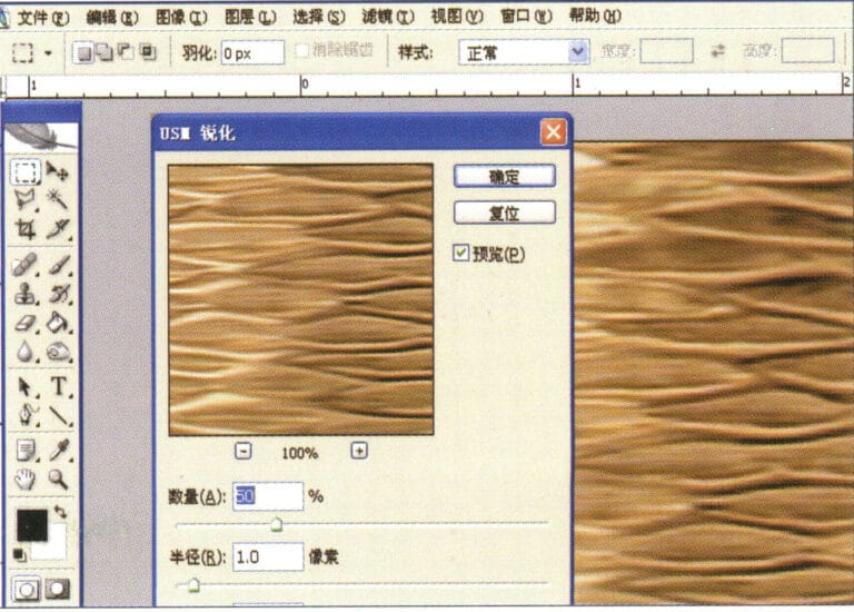
3. Select "Filter" > "Sharpen" > "USM Sharpening" from the menu bar
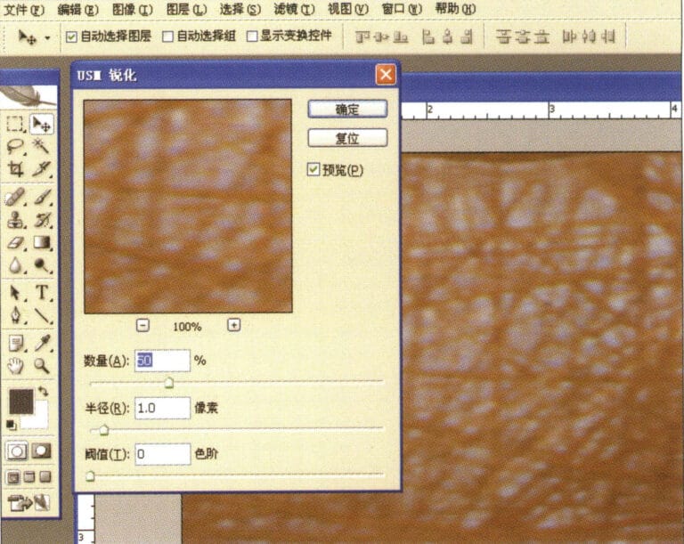
4. Entre en el cuadro de diálogo "USM Sharpening", introduzca los valores correspondientes y confirme
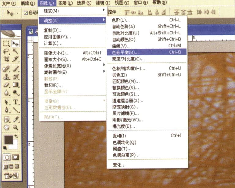
5. Select "Image" > "Adjustments" > "Color Balance" from the menu bar
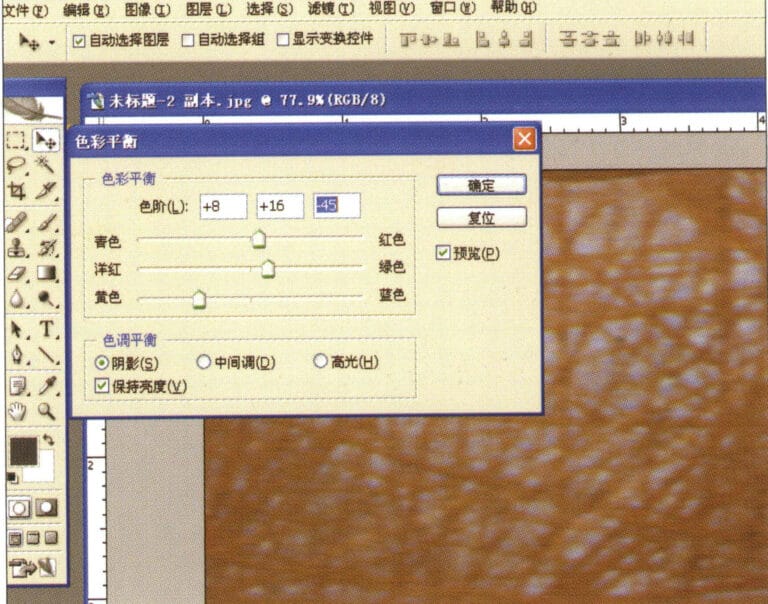
6. Entre en el cuadro de diálogo "Equilibrio de color", introduzca los valores correspondientes y confirme
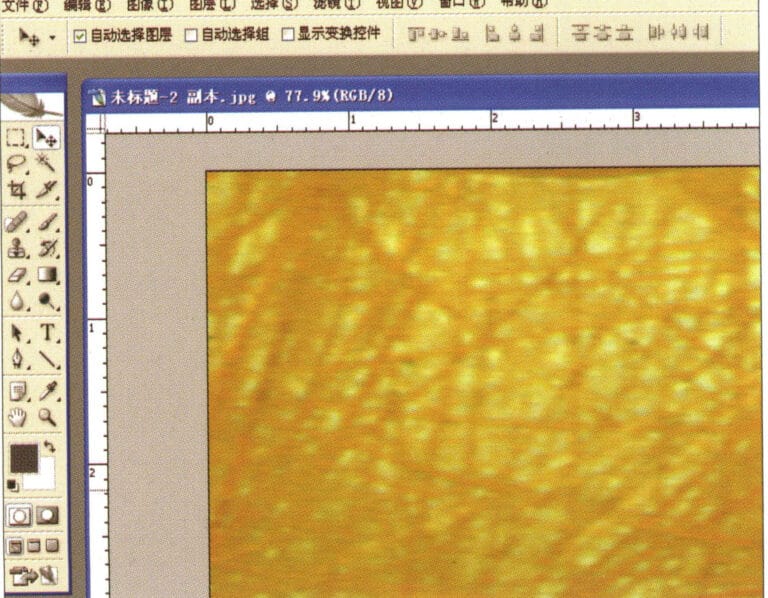
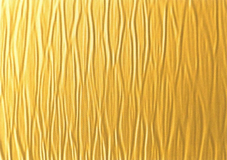
7. Diagrama de efectos tras visualizar el balance de color
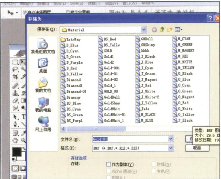
8. Store the document in the "JewelCAD" > "Material" folder, saved in "BMP" format
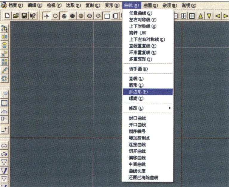
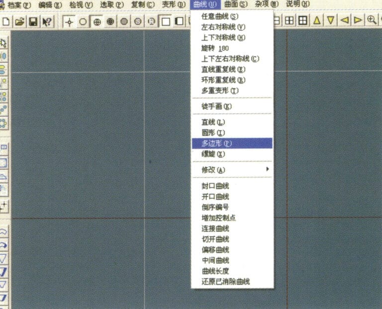
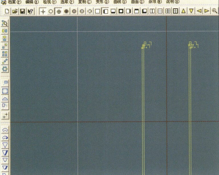
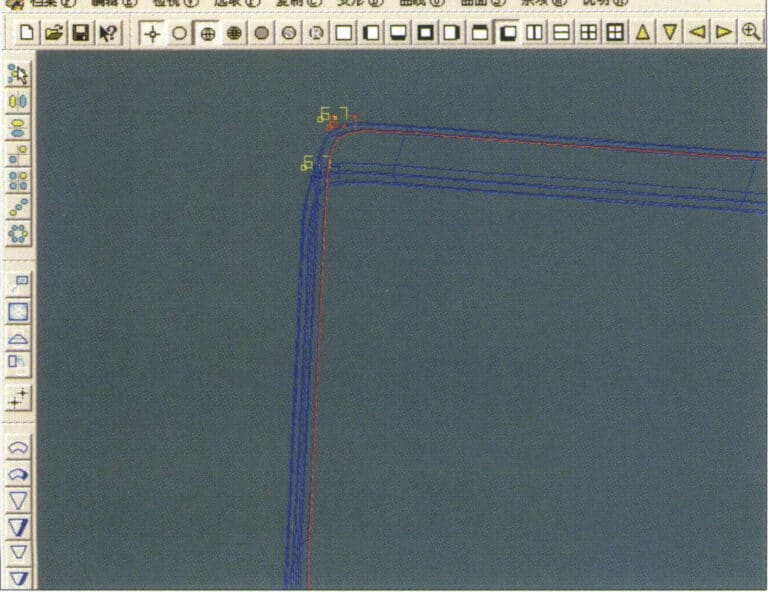
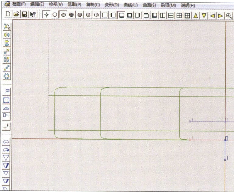
9. In JewelCAD, create a new file, select "Curve" > "Polygon" from the menu bar
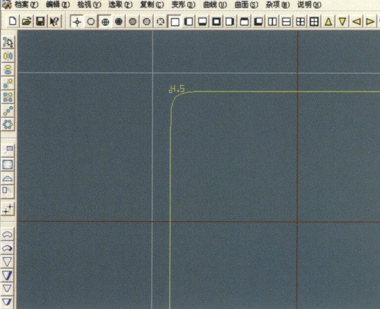
10. Utiliza "polígono" para dibujar un cuadrado
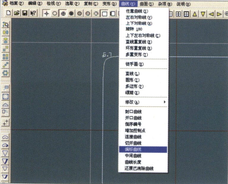
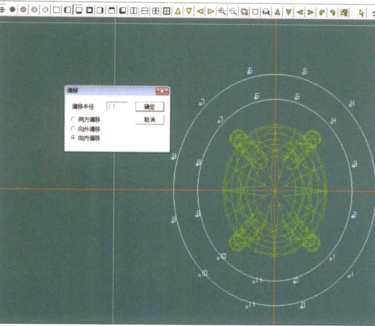
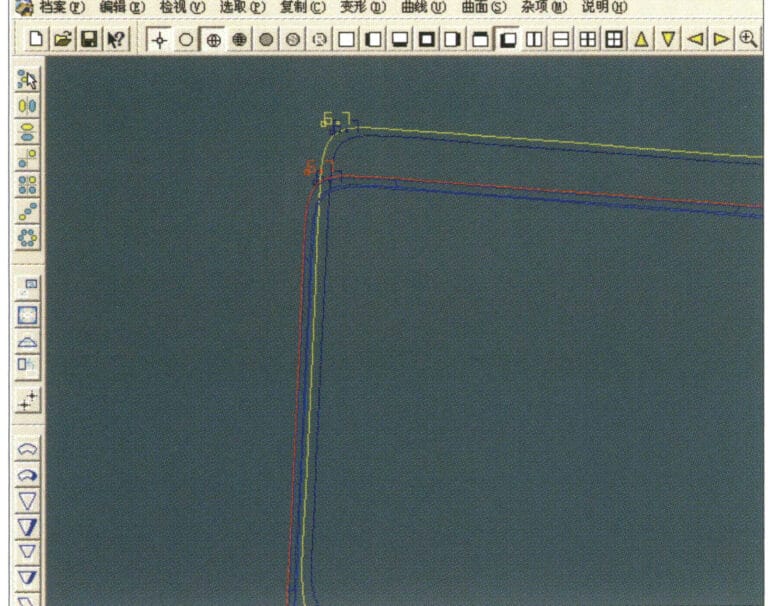
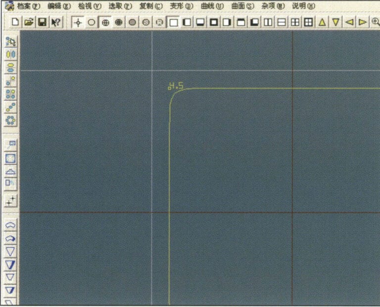
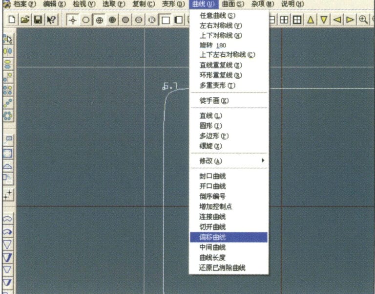
11. Select "Curve" > "Offset Curve" from the menu bar
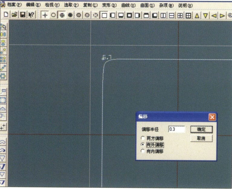
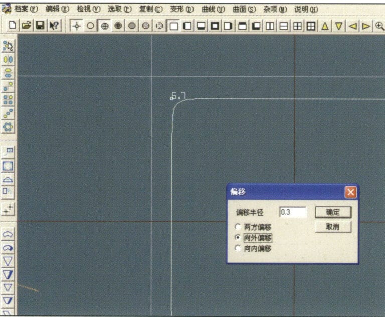
12. Entre en el cuadro de diálogo "Curva de desplazamiento", introduzca los valores correspondientes y confirme
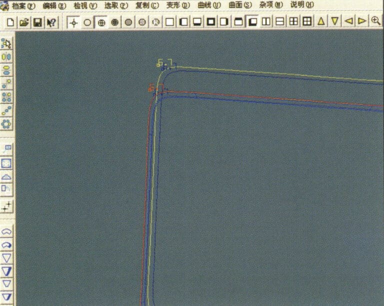
13. Diagrama de efectos tras visualizar la curva de desplazamiento
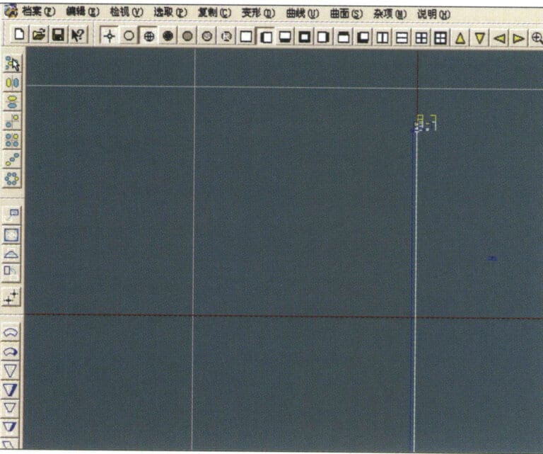
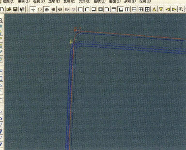
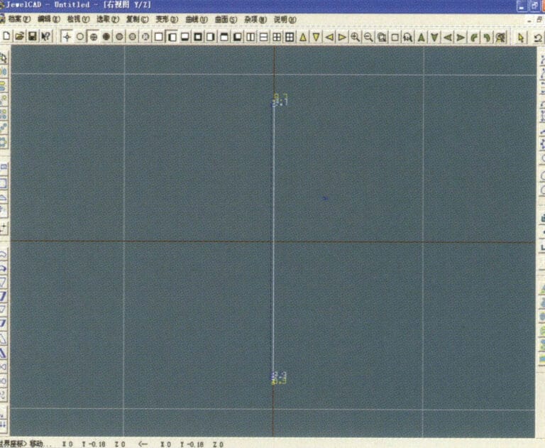
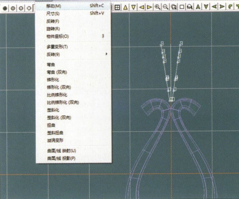
14. Select "Deformation" > "Move" from the menu bar to move the selected curve
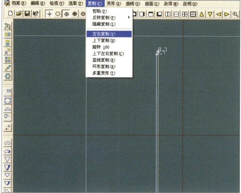
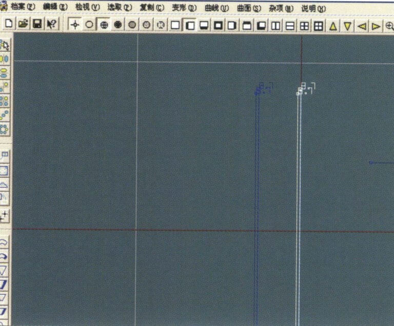
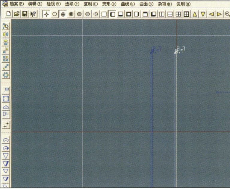
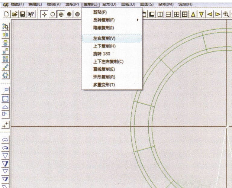
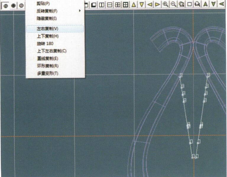
15. Select "Copy" > "Copy Left and Right" from the menu bar to copy the selected curve to the left and right

16. Visualizar las imágenes de efecto después de la duplicación izquierda y derecha.
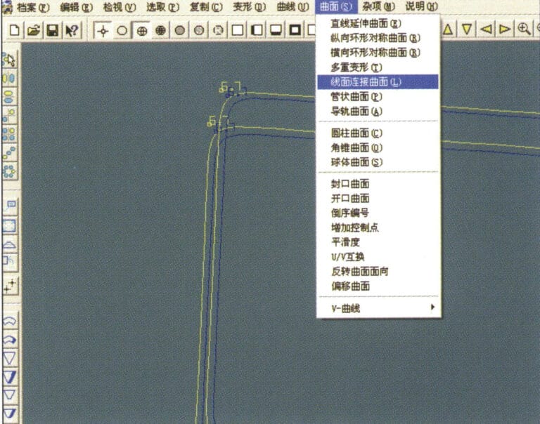
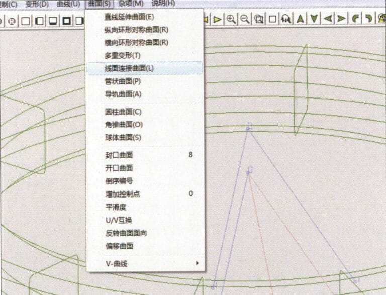
17. Select "Surface" > "Curve Surface Connection" from the menu bar, and double-click the first and second curves/surfaces in a clockwise direction with the left mouse button to create a curve surface connection
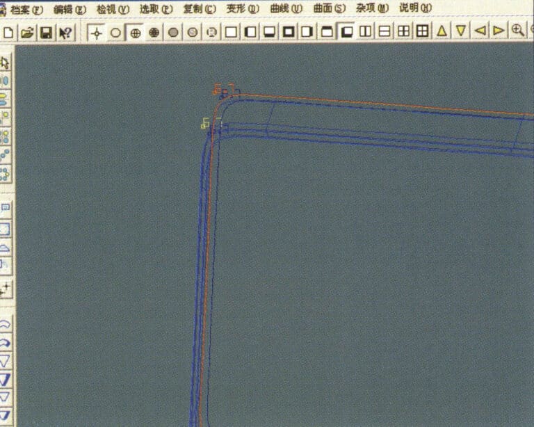
18. En el sentido de las agujas del reloj, haga doble clic en la tercera curva/superficie con el botón izquierdo del ratón para crear una conexión línea-superficie
19. Continúe en el sentido de las agujas del reloj; haga doble clic en la cuarta curva/superficie con el botón izquierdo del ratón para crear una conexión línea-superficie

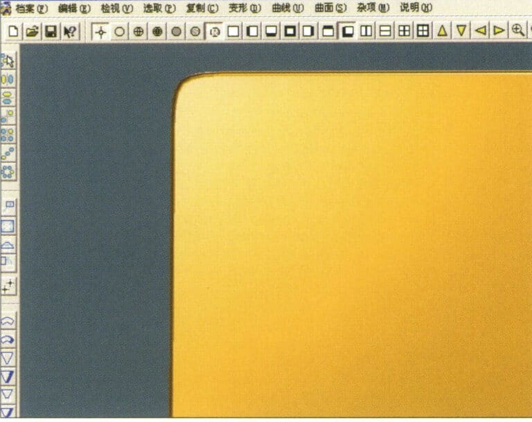
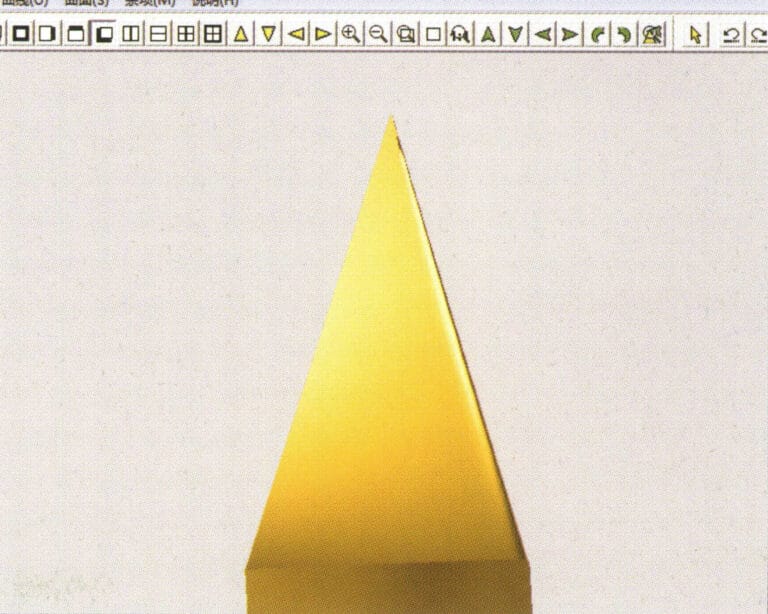
20. Select "View" > "Shadow Map" from the menu bar to inspect the shadow effects
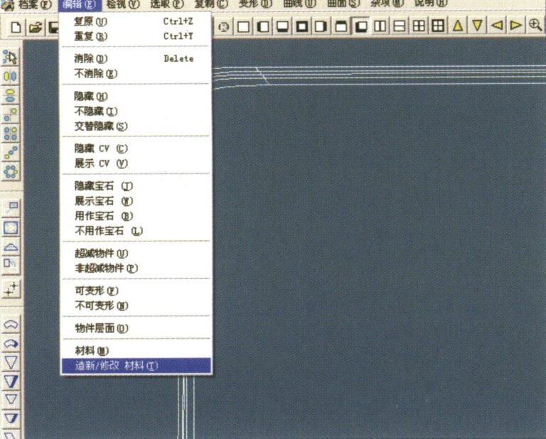
21. Select "Edit" > "Create/Modify Material" from the menu bar
22. Acceda al cuadro de diálogo "Crear/Modificar material", introduzca los valores correspondientes y confirme
23. Select "Edit" > "Materials" from the menu bar
24. Select "View" > "Shadow Map" on the menu bar to view the light and shadow effects 25. Select "File" > "Save File" on the menu bar to save the file

1. Escanea un archivo de textura en Photoshop con una resolución de 300 píxeles/pulgada.
2. Select "Filter" > "Blur" > "Motion Blur" from the menu bar
3. Acceda al cuadro de diálogo "Desenfoque de movimiento", introduzca los valores correspondientes y confirme
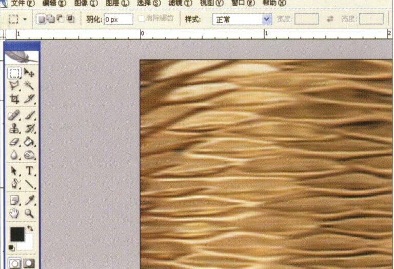
4. Visualizar la imagen del efecto después del desenfoque de movimiento
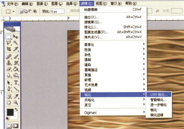
5. Select "Filter" > "Sharpen" > "USM Sharpening" from the menu bar
6. Entre en el cuadro de diálogo "USM Sharpening", introduzca los valores correspondientes y confirme
7. Store the document in the "JewelCAD" > "Material" folder and save it in "BMP" format
8. In JewelCAD, create a new file, select "Curve" > "Polygon" from the menu bar
9. Utiliza "polígono" para dibujar un cuadrado
10. Select "Curve" > "Offset Curve" from the menu bar
11. Entre en el cuadro de diálogo "Curva de desplazamiento", introduzca los valores correspondientes y confirme
12. Diagrama de efectos tras visualizar la curva de desplazamiento
13. Select "Deformation" > "Move" from the menu bar to move the selected curve

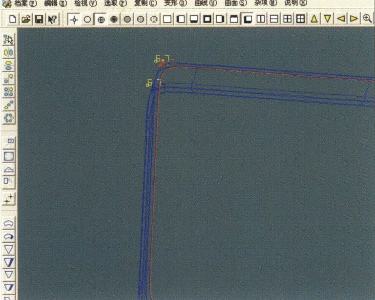
14. Select "Copy" > "Copy Left and Right" from the menu bar to copy the selected curve to the left and right
15. Visualizar las imágenes de efecto después de copiar izquierda y derecha
16. Select "Surface" > "Line-Surface Connection Surface" from the menu bar, and select the curve/surface to create a line-surface connection surface
17. Select the menu bar "Surface" > "Curve Surface Connection," and double-click the first and second curves/surfaces with the left mouse button in a clockwise direction to create a curve surface connection
18. En el sentido de las agujas del reloj, haga doble clic en la tercera curva/superficie con el botón izquierdo del ratón para crear una conexión línea-superficie
19. Continúe en el sentido de las agujas del reloj; haga doble clic en la cuarta curva/superficie con el botón izquierdo del ratón para crear una conexión línea-superficie
20. Select "View" > "Shadow Map" from the menu bar to inspect the shadow effects
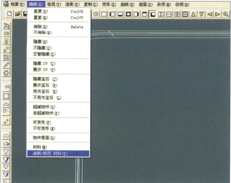
21. Select "Edit" > "Create/Modify Material" from the menu bar
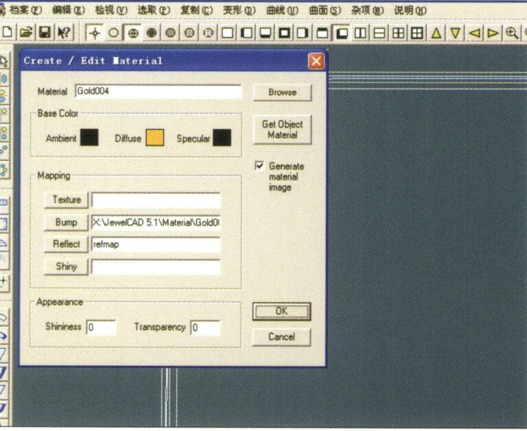
22. Acceda al cuadro de diálogo "Crear/Modificar material", introduzca los valores correspondientes y confirme
23. Select “Edit” > “Material” in the menu bar
24. Select "View" > "Shadow Map" from the menu bar to examine the shadow effects
25. Select "File" > "Save As" from the menu bar to save the file

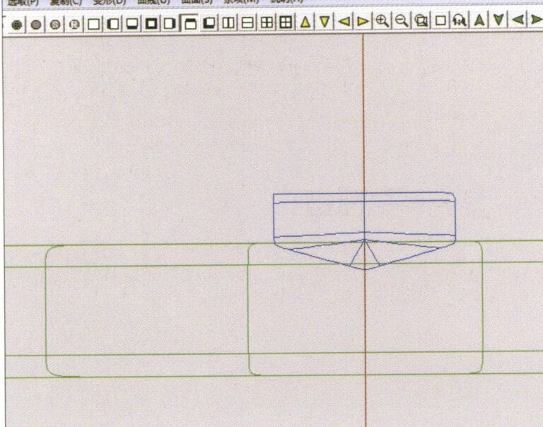
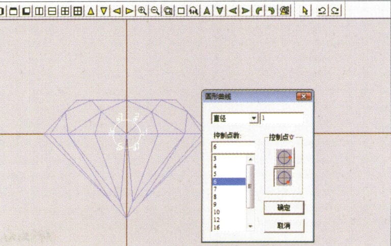
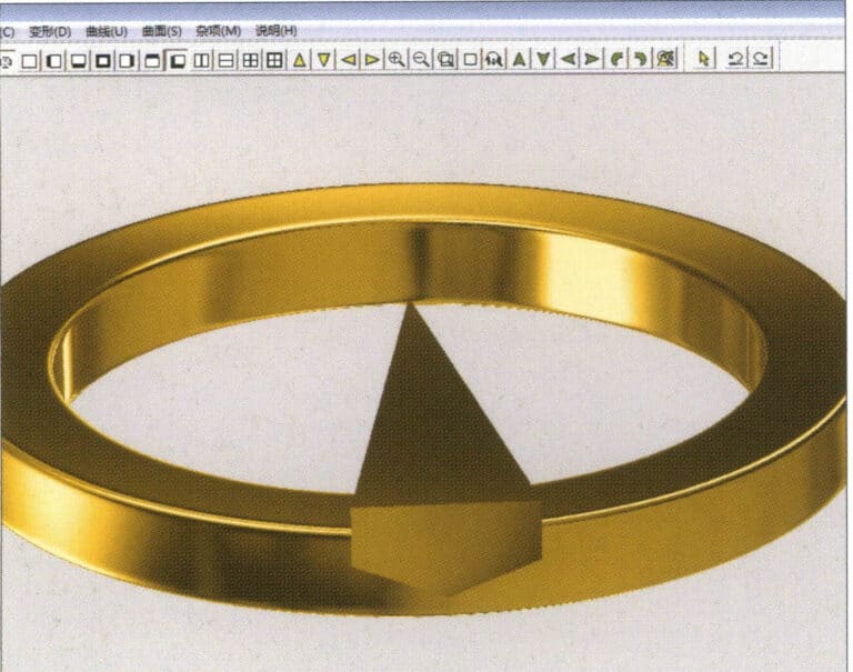
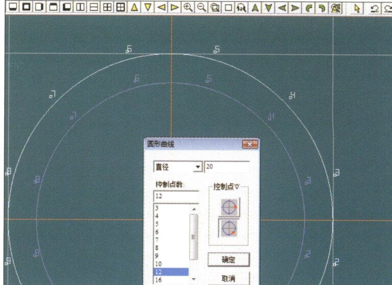
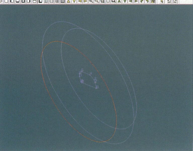
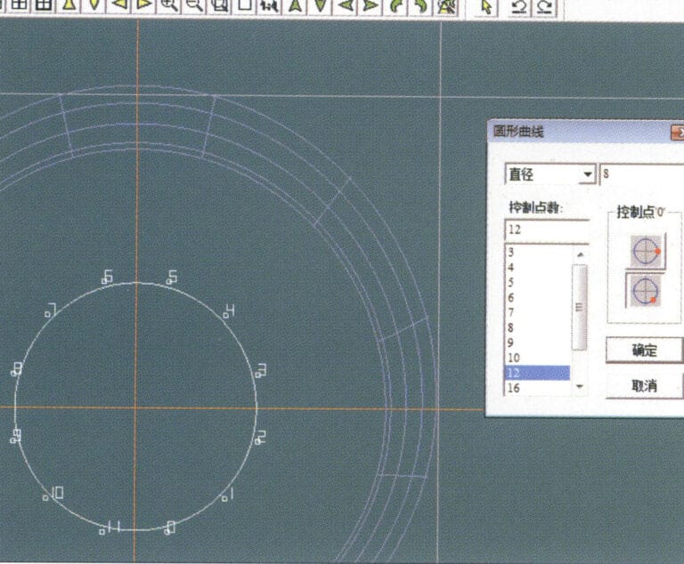
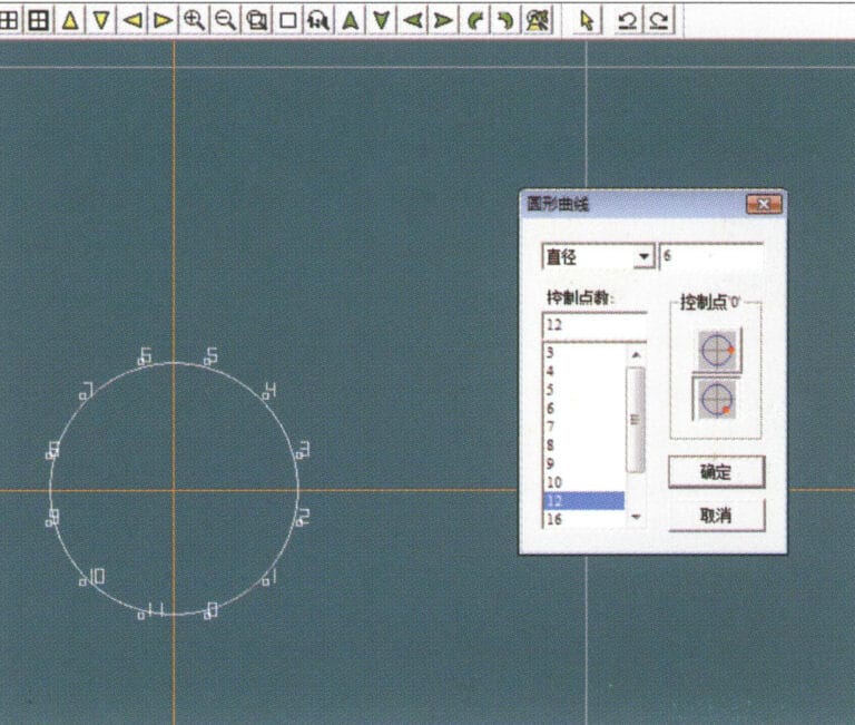
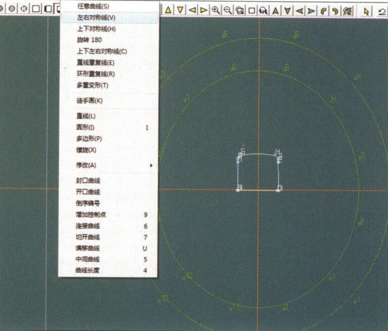
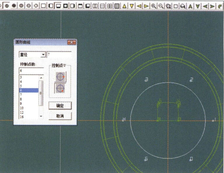
1. Create a new file in JewelCAD, select "Curve" > "Circular Curve" from the menu bar, enter the relevant values in the "Circular Curve" dialog box, and confirm
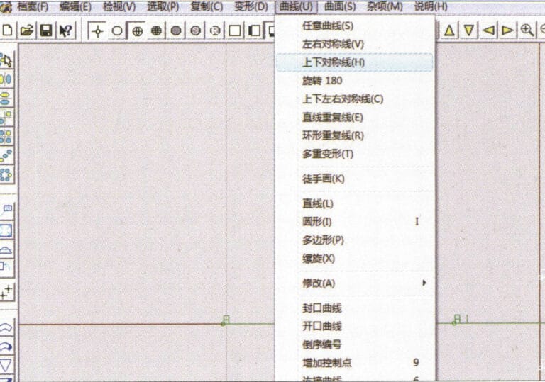
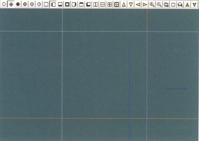
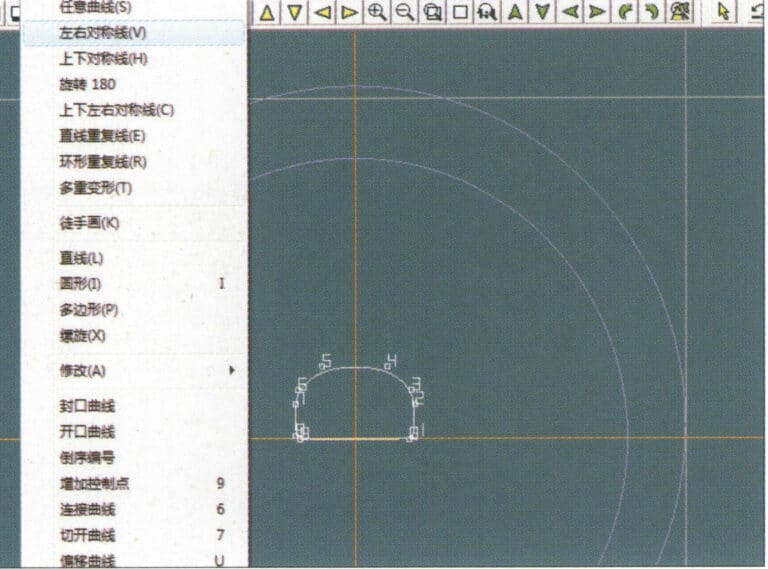
2. Select "Curve" > "Left-Right Symmetry Line" from the menu bar to draw a section
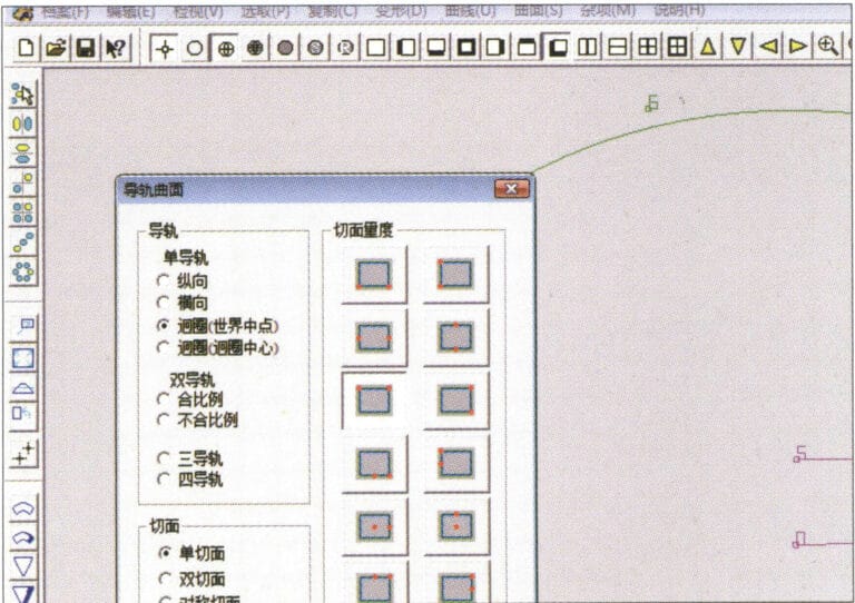
3. Select "Surface" > "Rail Surface" from the menu bar, enter "Rail Surface," select the relevant options and confirm; left-click on a curve as the section of the rail surface; left-click on another curve as the "Rail" > "Finish."

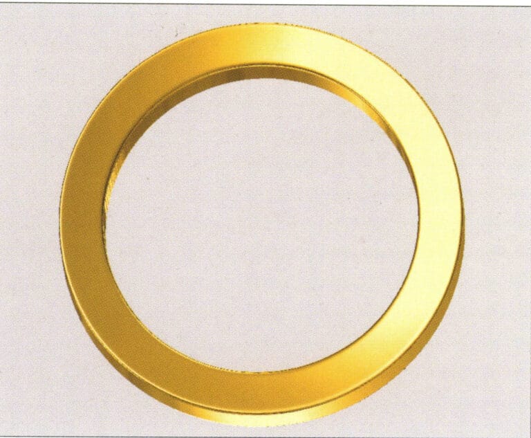
4. Select “View” > “Shadow Map” on the menu bar to view the light and shadow effects
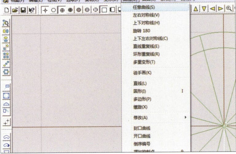
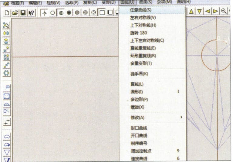
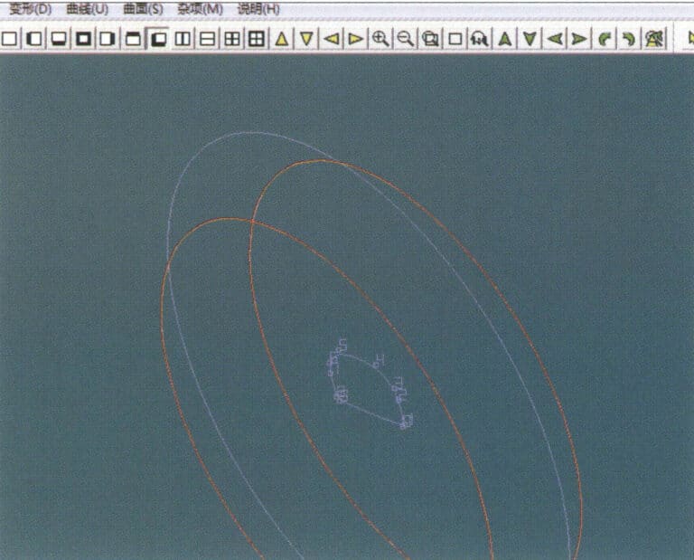
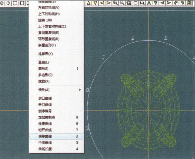
5. Select "Curve" > "Freefrom Curve" from the menu bar
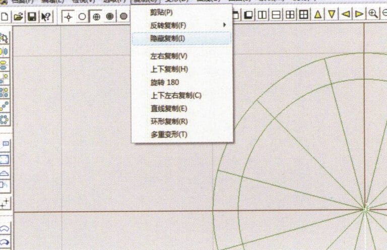
6. Select "Copy" > "Hide Copy" from the menu bar
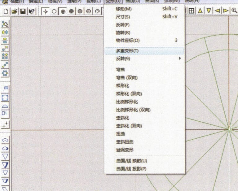
7. Select "Deformation" > "Multiple Deformation" from the menu bar
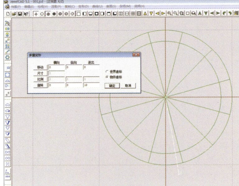
8. Acceda al cuadro de diálogo "Deformación múltiple" e introduzca los valores correspondientes
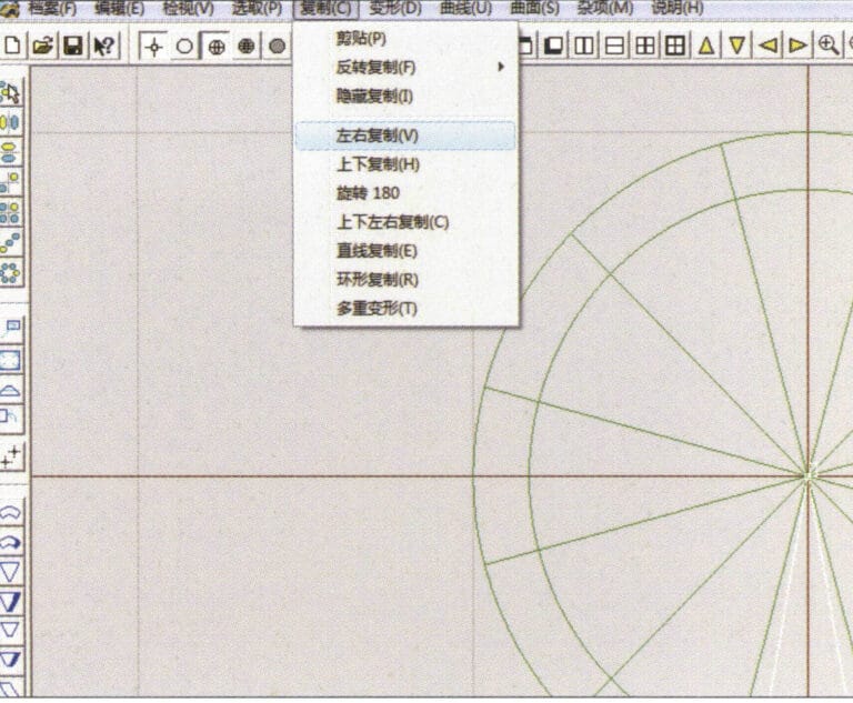
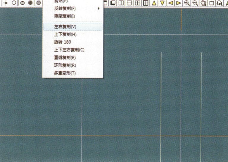
9. Select “Copy” > “Left/Right Copy” on the menu bar
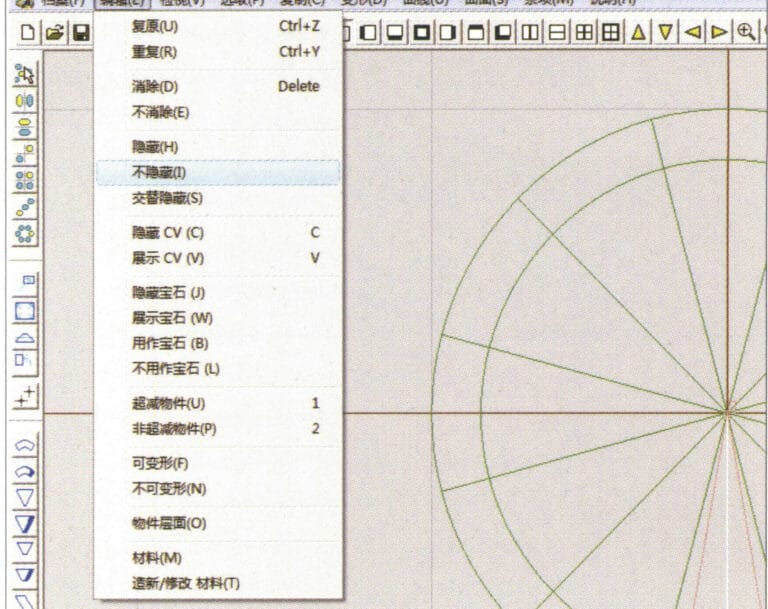
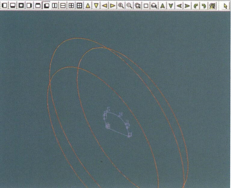
10. Select "Edit" > "Unhide" from the menu bar to display the hidden curves
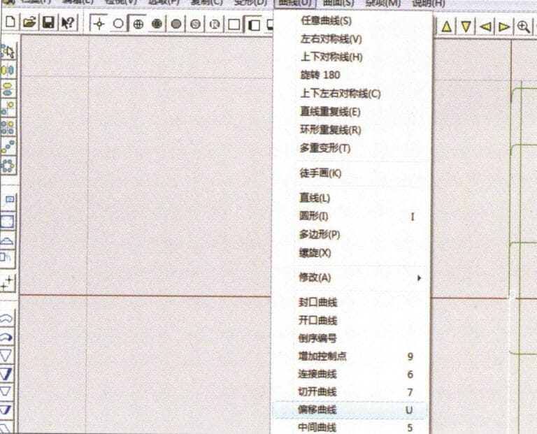
11. Select "Curve" > "Offset Curve" from the menu bar
12. Select "Deformation" > "Move" from the menu bar to move the selected curve
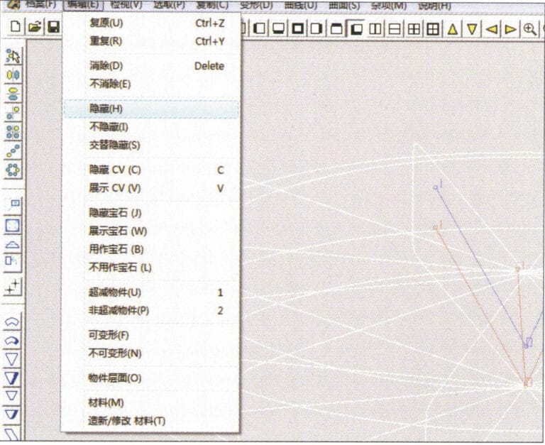
13. Select "Edit" > "Hide" from the menu bar to hide the circular surface
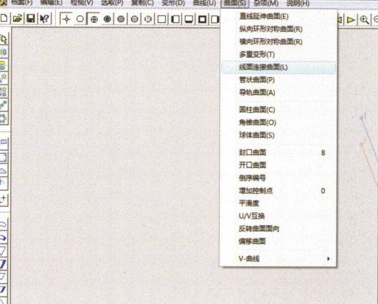
14. Select "Surface" > "Line Surface Connection Surface" from the menu bar

15. Seleccione curvas/superficies en el sentido de las agujas del reloj para crear conexiones línea-superficie y, a continuación, seleccione en la barra de menús
16. Select "View" > "Shadow Map" from the menu bar to inspect the shadow effects
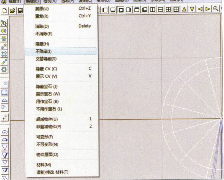
17. Select "Edit" > "Unhide" from the menu bar to display the hidden circular surfaces
18. Select "Deformation" > "Move" from the menu bar to move the selected surface
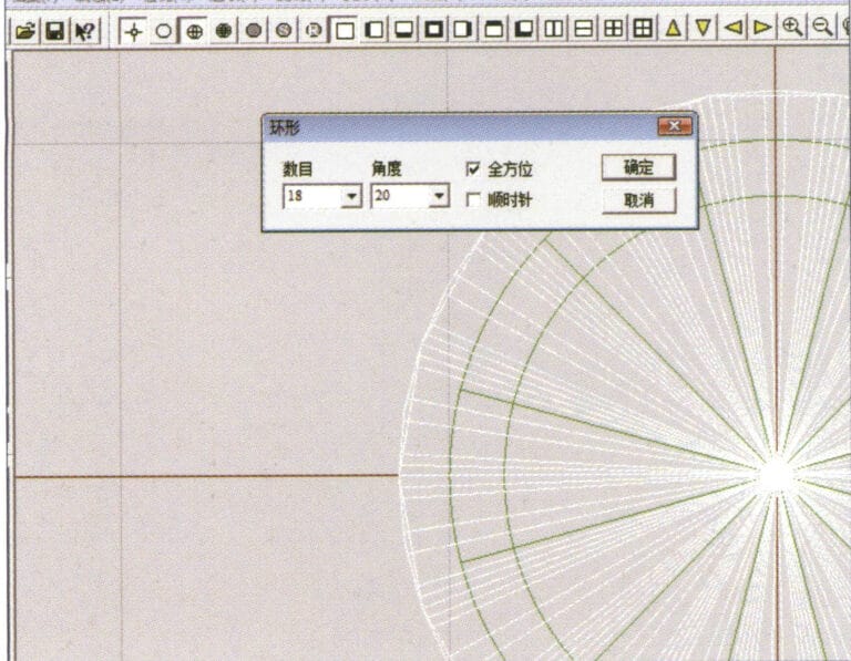
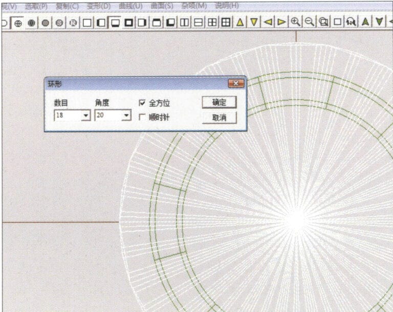
19. Select "Copy" > "Circular Copy" from the menu bar, enter the relevant values and confirm

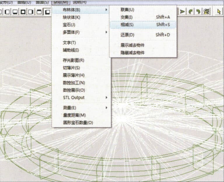
20. Select “Miscellaneous” > “Boolean” > “Integrate” on the menu bar to integrate the selected surfaces.
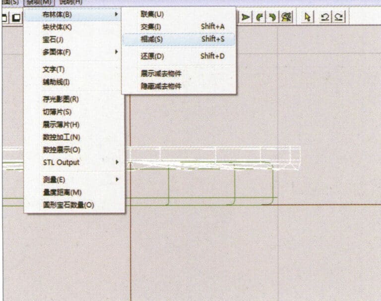
21. Select "Miscellaneous" > "Boolean" > "Subtract" from the menu bar to subtract the selected surface from the already united surface
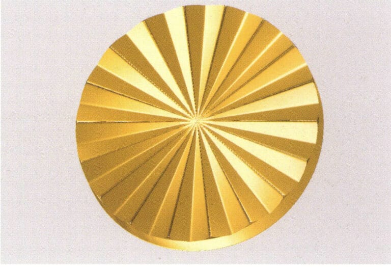
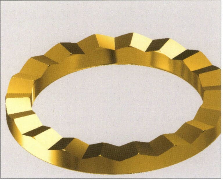
22. Select "View" > "Shadow Map" from the menu bar to inspect the shadow effects.
23. Select "File" > "Save File" from the menu bar to save the document
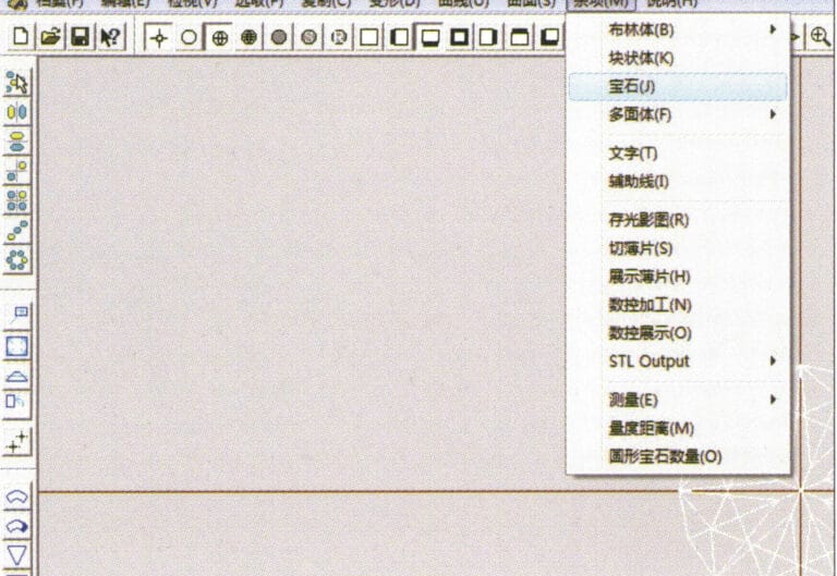
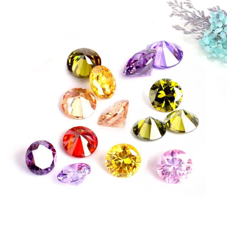
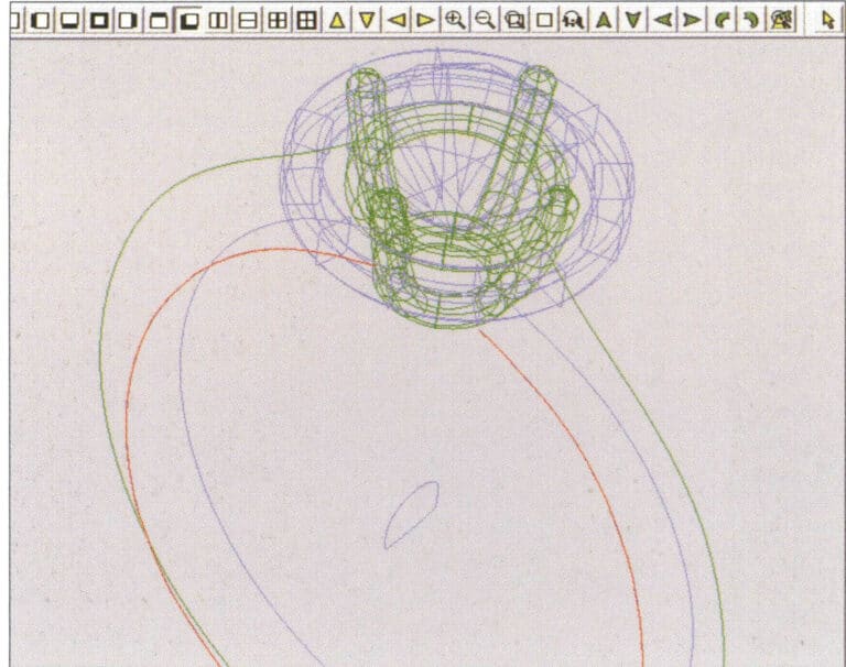
1. Create a new file in JewelCAD, select "Miscellaneous" > "Gem" from the menu bar

2. Select "Deformation" > "Multiple Deformation" from the menu bar
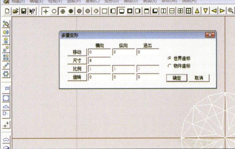
3. Acceda al cuadro de diálogo "Deformación múltiple", introduzca los valores correspondientes y confirme
4. Select “Curve” > “Circular Curve” in the menu bar to enter the “Circular Curve” dialog box, enter the relevant values and confirm
5. Select "Curve" > "Freeform Curve" from the menu bar to draw a claw-shaped guideline
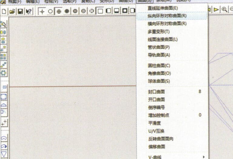
6. Select "Surface" > "Longitudinal Annular Symmetrical Surface" from the menu bar, and draw a claw shape
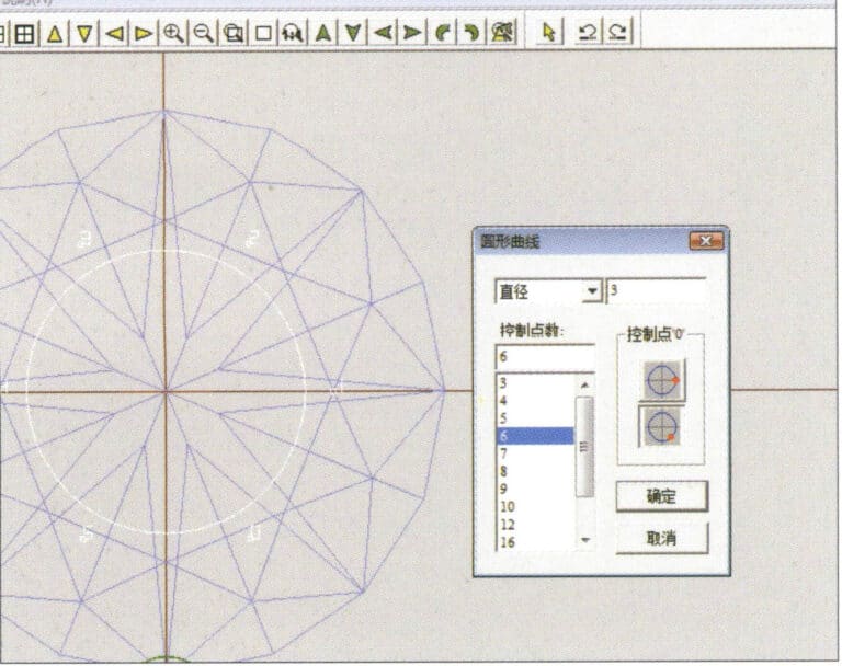
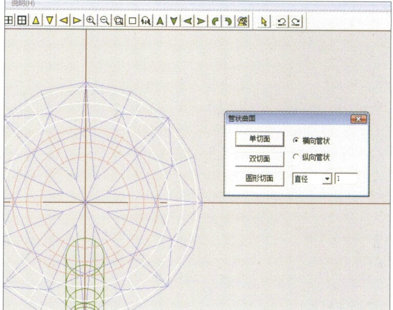
7. Select "Curve" > "Circular Curve" from the menu bar, enter the relevant values in the "Circular Curve" dialog box and confirm
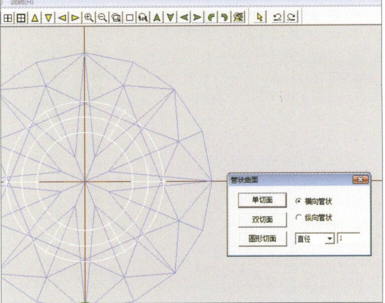
8. Select "Surface" > "Tubular Surface" from the menu bar, enter the relevant values and confirm
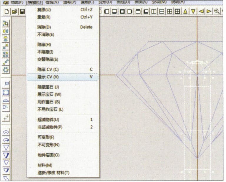
9. Select “Edit” > “Show CV” in the menu bar
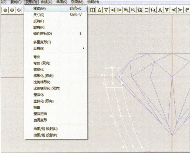
10. Select “Deformation” > “Move” in the menu bar to move the CV
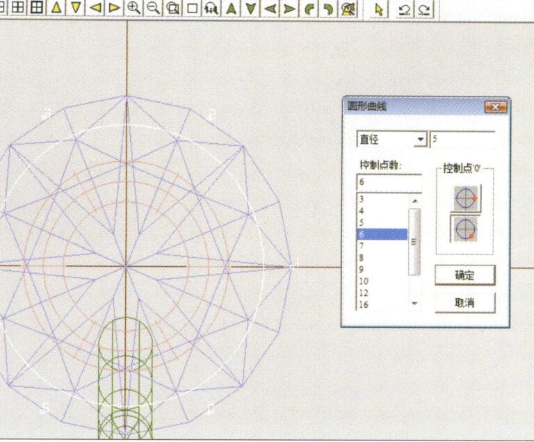
11. Select "Curve" > "Circular Curve" from the menu bar, enter the relevant values in the "Circular Curve" dialog box and confirm
12. Select "Surface" > "Tubular Surface" from the menu bar, enter the relevant values and confirm
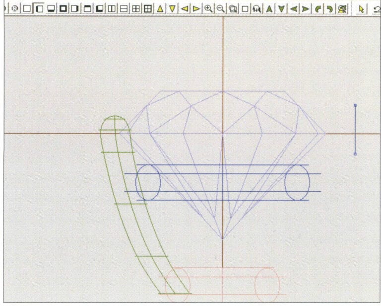
13. Select the menu bar "Edit" > "Move" to move the selected graphic

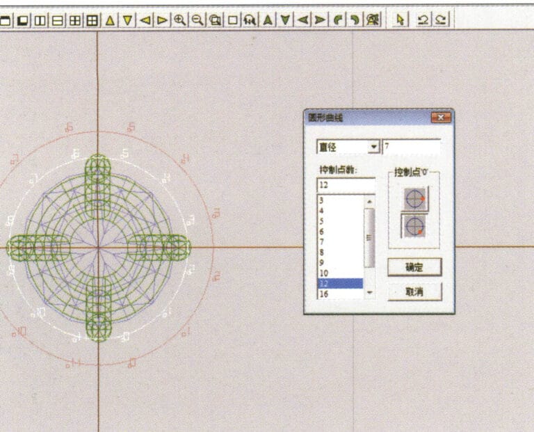
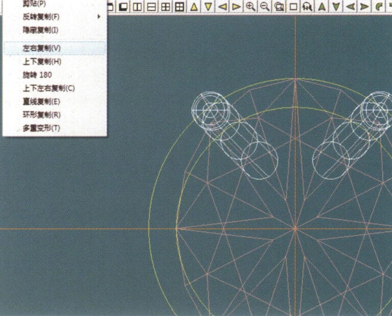
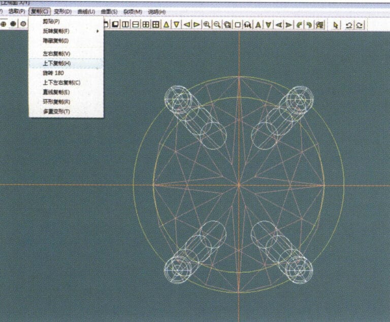
14. Select the completed claw shape, choose "Copy" > "Circular Copy" from the menu, enter the relevant values in the "Circular Copy" dialog box and confirm
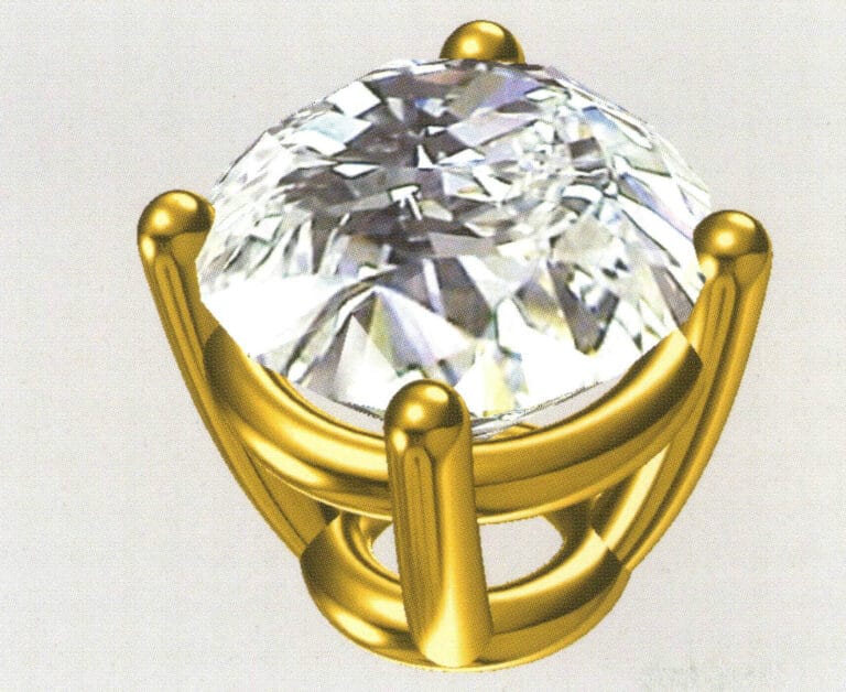
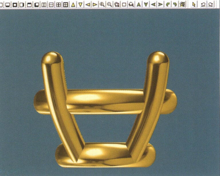
15. Select "View" > "Shadow Map" from the menu bar to inspect the shadow effects
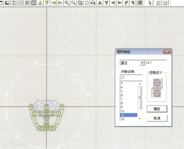
16. Select "Curve" > "Circular Curve" from the menu bar, enter the "Circular Curve" dialog box, and input the relevant values as the inner diameter of the ring shank
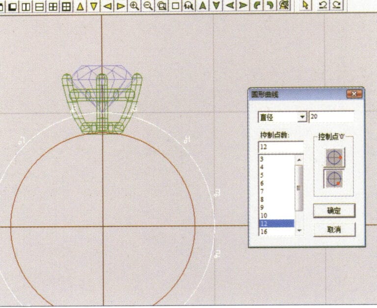
17. Select "Curve" > "Circular Curve" from the menu bar, enter the "Circular Curve" dialog box, and input the relevant values as the outer diameter of the ring shank

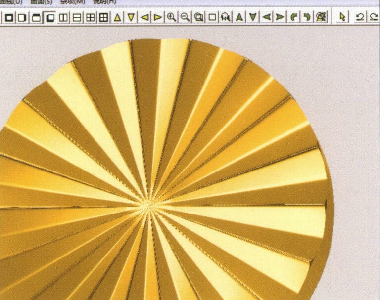
18. Select "Curve" > "Circular Curve" from the menu bar, enter the "Circular Curve" dialog box, and input the relevant values as the outer diameter of the engine-turned band
19. Select "Curve" > "Circular Curve" from the menu bar, enter the "Circular Curve" dialog box, and input the relevant values as the inner diameter of the engine-turned band
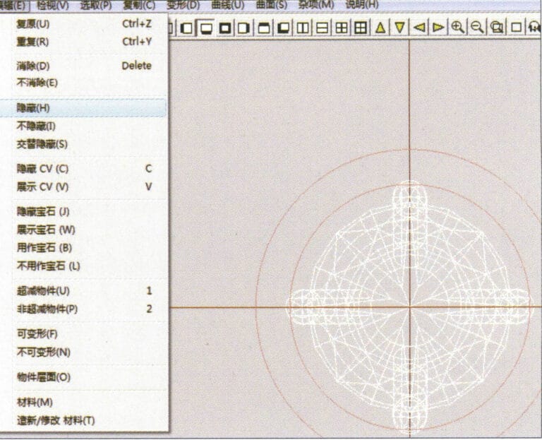
20. Select "Edit" > "Hide" from the menu bar to hide the completed gemstone inlay
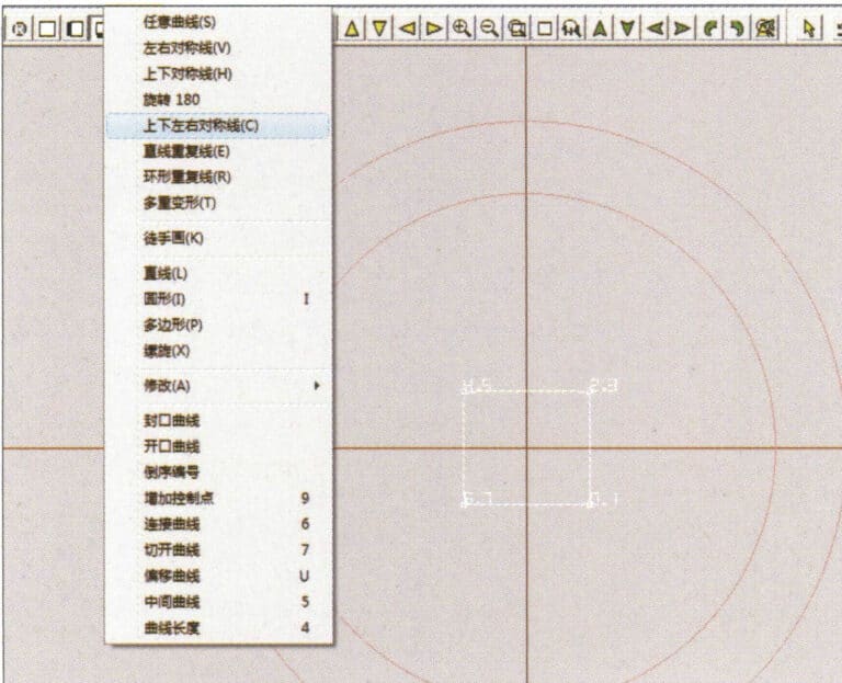
21. Select "Curve" > "Vertical and Horizontal Symmetry Line" from the menu bar
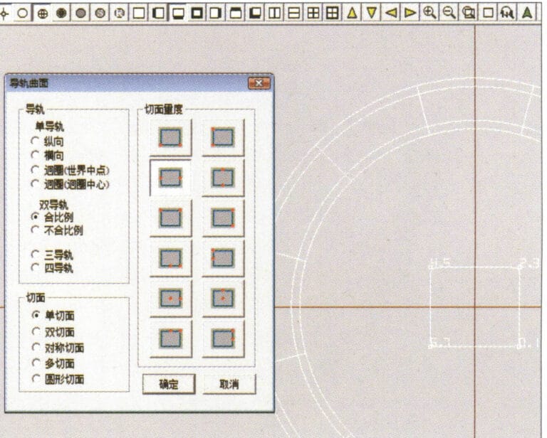
22. Select "Surface" > "Rail Surface" from the menu bar to enter the "Rail Surface" dialog box, select the relevant options and confirm
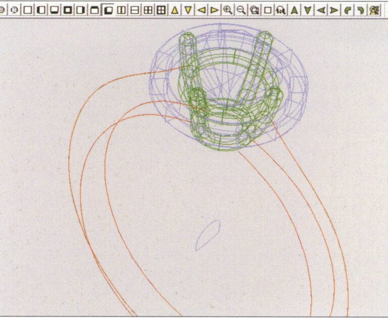
23. Select "View" > "Shadow Map" from the menu bar to inspect the shadow effects
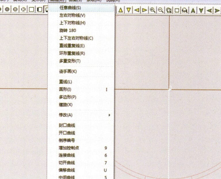
24. Select "Curve" > "Freeform Curve" from the menu bar to draw a guideline

25. Select "Copy" > "Hide Copy" from the menu bar to copy the already drawn auxiliary lines
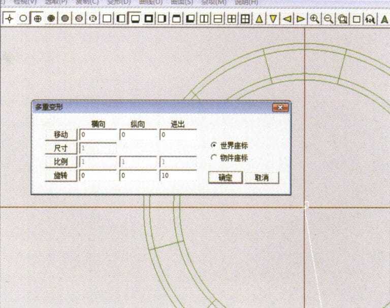
26. Select “Deformation” > “Multiple Deformation” in the menu bar to enter the “Multiple Deformation” dialog box, enter the relevant values and confirm
27. Select “Copy” > “Copy Up and Down” in the menu bar to copy the drawn auxiliary lines
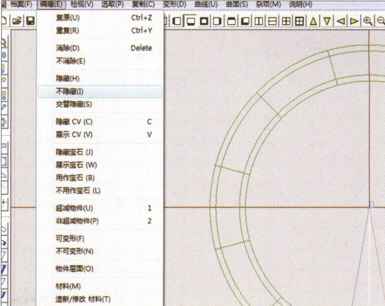
28. Select "Edit" > "Unhide" from the menu to display the hidden curves
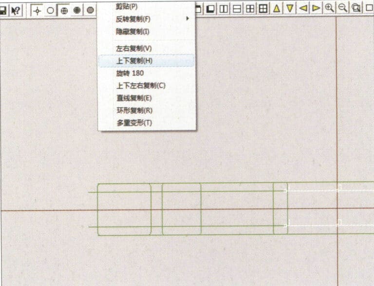
29. Select "Copy" > "Copy Up and Down" from the menu bar to copy the selected curve
30. Select curves/surfaces in a clockwise direction to create line-surface connections, then select "Surface" > "Cap Surface" from the menu bar
31. Select "View" > "Shadow Map" from the menu bar to inspect the shadow effects
32. Select "Copy" > "Circular Copy" from the menu bar, enter the relevant values and confirm
33. Select "Miscellaneous" > "Boolean" > "Subtract" from the menu bar to subtract the selected surface from the already united surface
34. Select "View" > "Shadow Map" from the menu bar to inspect the shadow effects
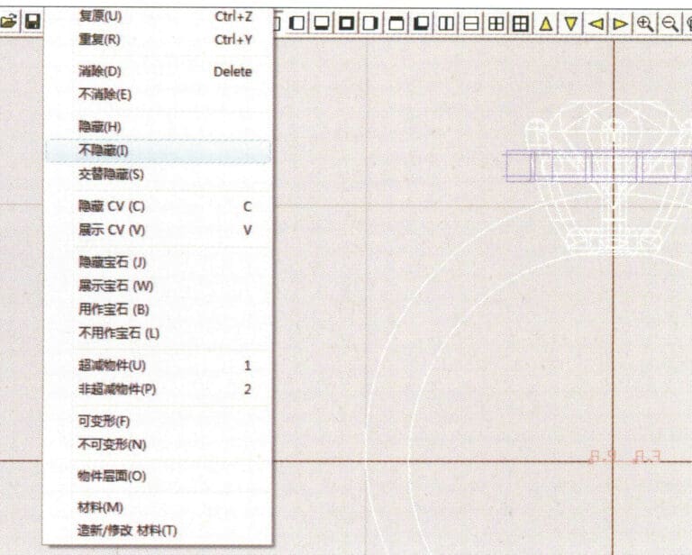
35. Select "Edit" > "Unhide" from the menu bar to display the hidden objects
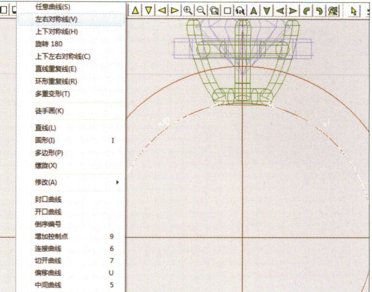
36. Select "Curve" > "Left-Right Symmetry Line" from the menu bar to draw the inner diameter of the ring wall
37. Select "Curve" > "Left-Right Symmetry Line" from the menu bar to draw the outer diameter of the ring wall
38. Select “Curve” > “Left-Right Symmetry Line” in the menu bar to draw a cutout of the ring shank
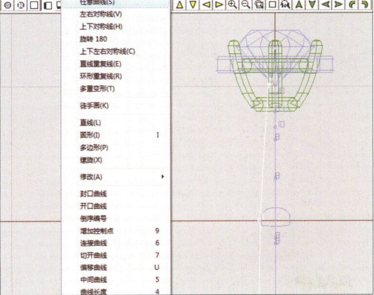
39. Select "Curve" > "Freeform Curve" from the menu bar to draw a guideline
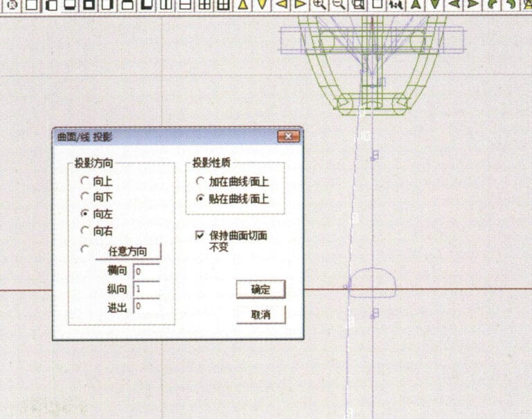
40. Select "Deformation" > "Surface/Line Projection" from the menu bar to enter the "Surface/Line Projection" dialog box, input the relevant values and confirm
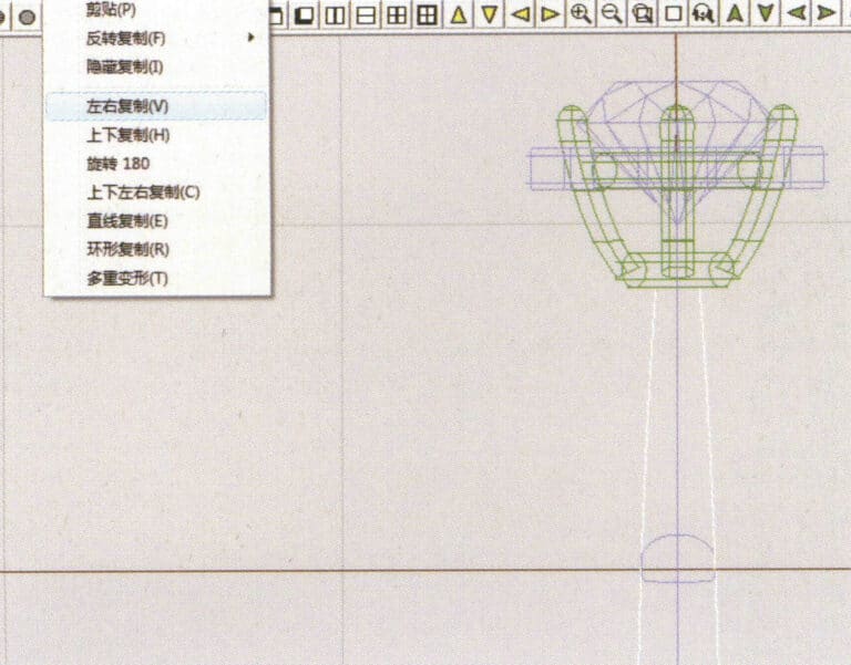
41. Select "Copy" > "Copy Left and Right" from the menu bar to copy the inner diameter of the ring shank
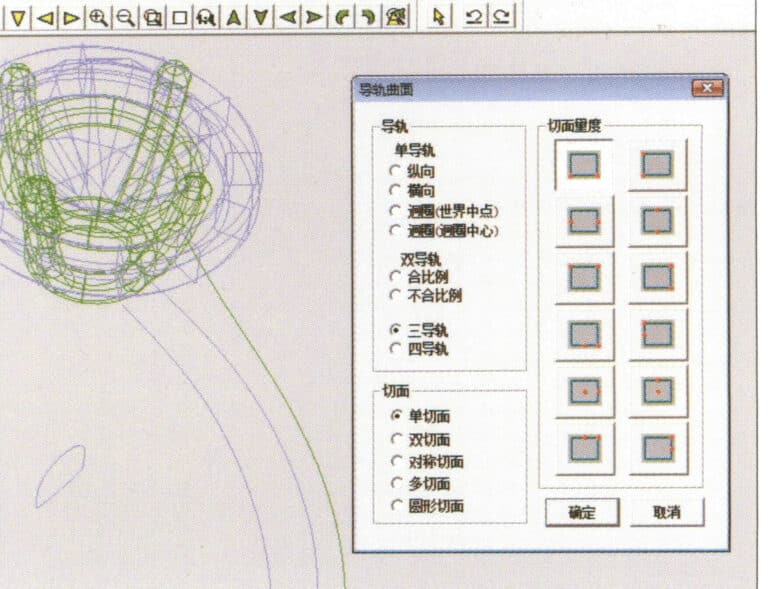
42. Select "Surface" > "Rail Surface" from the menu bar to enter the "Rail Surface" dialog box, select the relevant options and confirm
43. Seleccione una curva como carril guía izquierdo y, a continuación, seleccione una curva como carril guía derecho.

44. Seleccione una curva como carril guía superior
45. Seleccione una curva como sección transversal de la superficie guía.
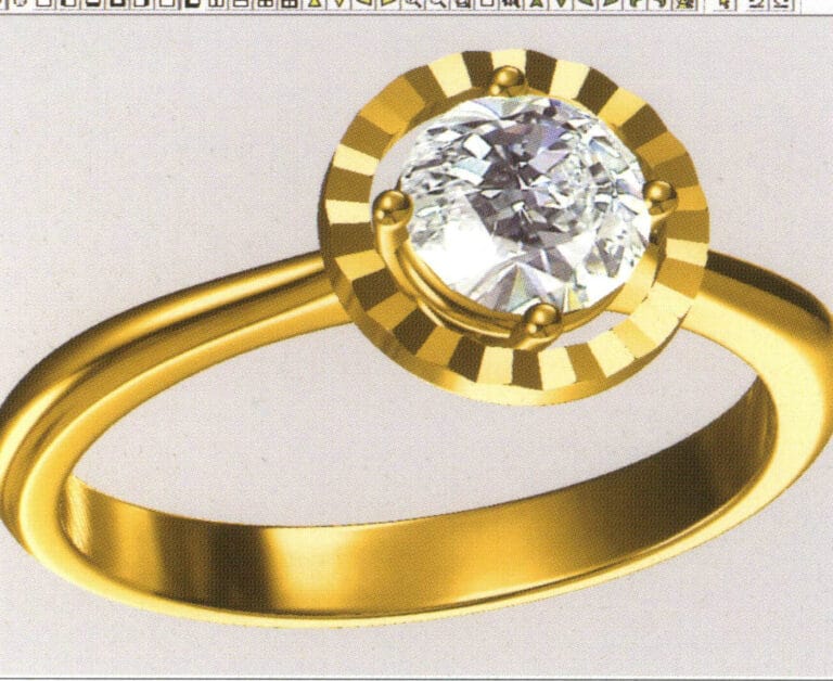
46. Select "View" > "Light and Shadow Map" from the menu bar to examine the light and shadow effects
47. Select "File" > "Save As" from the menu bar to save the file

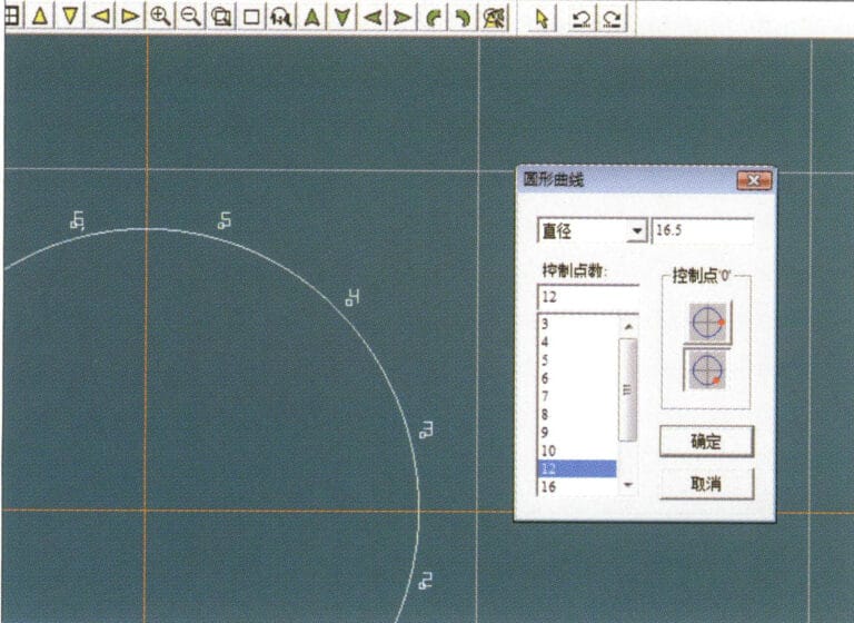
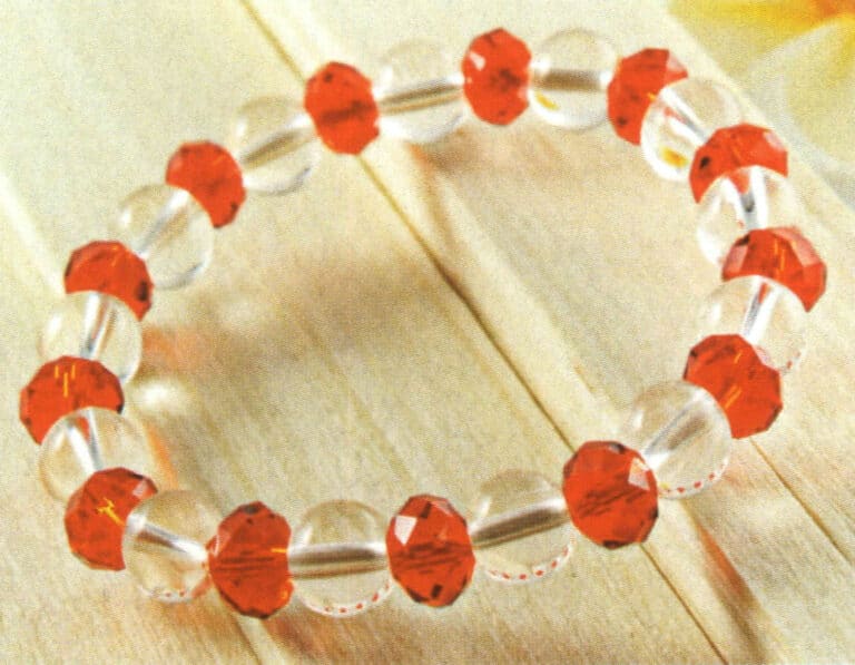
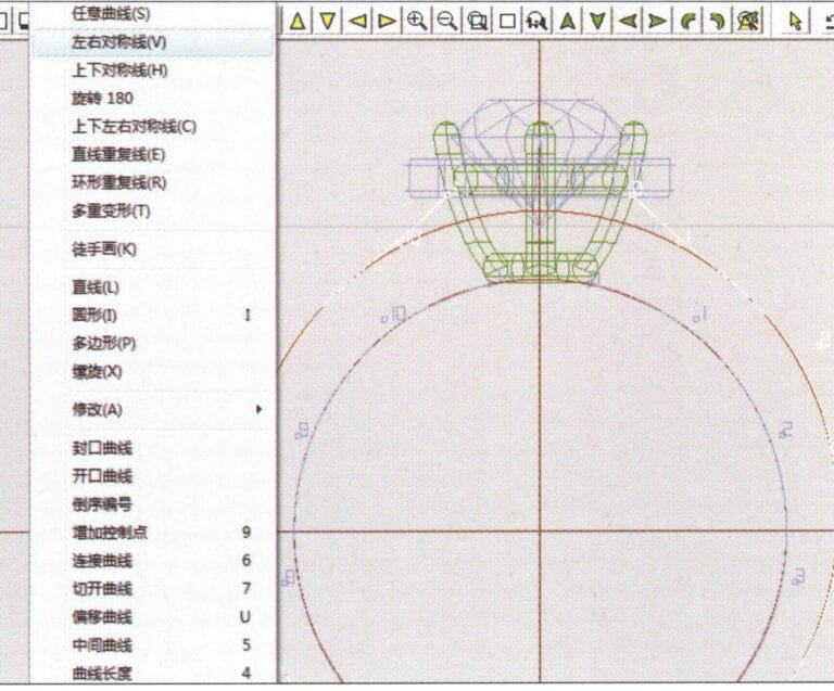
1. Create a new file in JewelCAD, select "Curve" > "Circular Curve" from the menu bar, enter the relevant values in the "Circular Curve" dialog box as the outer curve of the ring, and confirm
2. Select "Curve" > "Circular Curve" from the menu bar, enter the relevant values in the "Circular Curve" dialog box to set the inner curve of the ring, and confirm
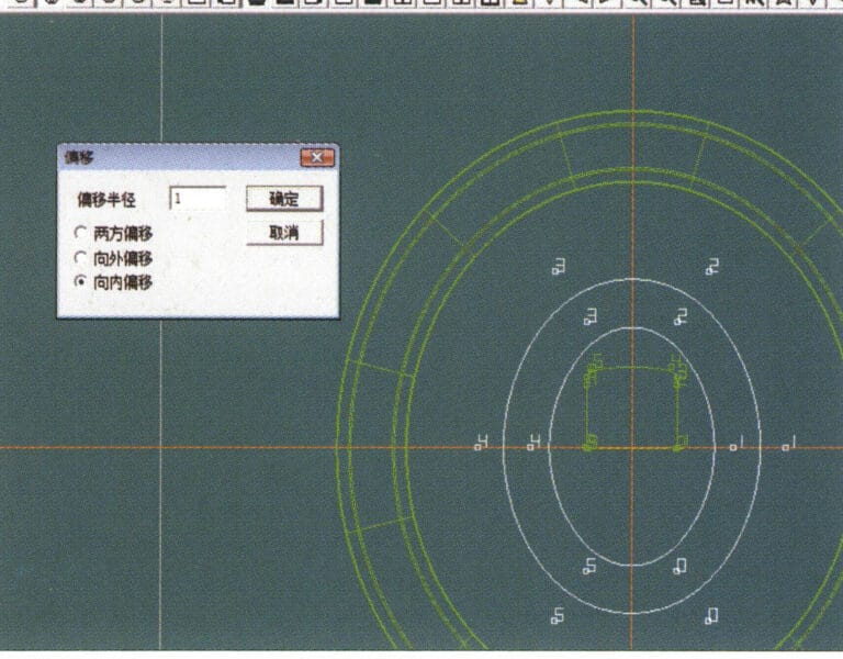
3. Select "Edit" > "Move" from the menu bar to move the selected inner curve of the ring
4. Select "Copy" > "Copy Left and Right" from the menu bar to copy the curve of the inner circle of the ring
5. Select "Curve" > "Left-Right Symmetry Line" from the menu bar as the cross-section of the ring band
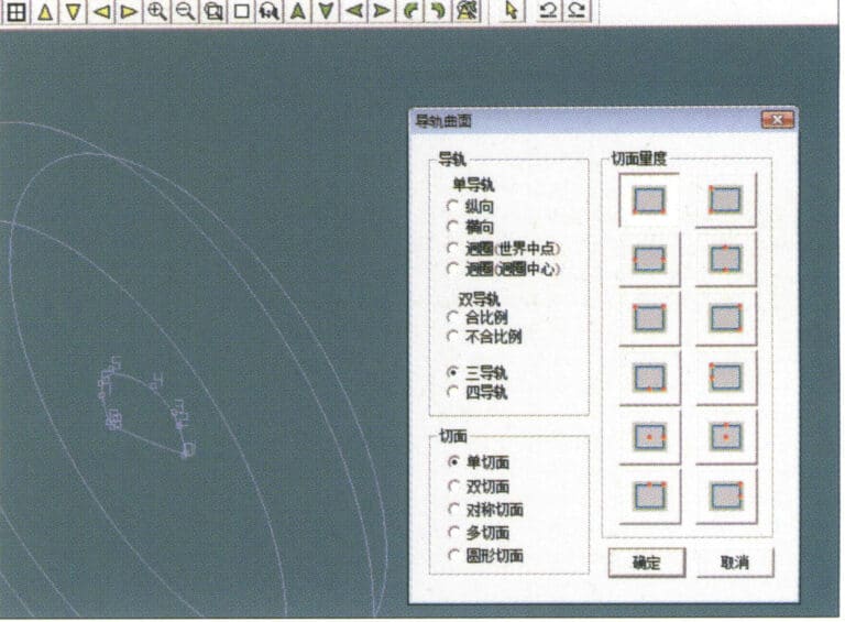
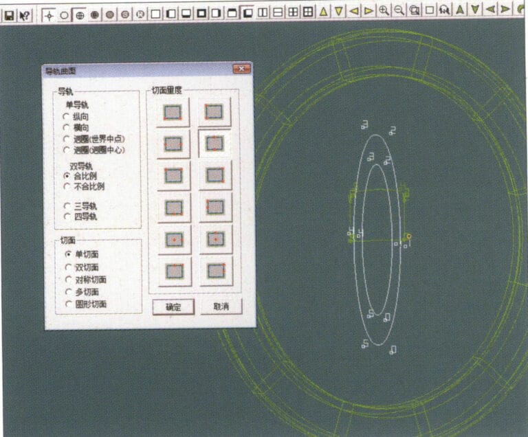
6. Select "Curved Surface" > "Guide Rail Surface" from the menu bar, enter the "Guide Rail Surface" dialog box, select the relevant options and confirm
7. Elija una curva como carril guía
8. Elija una curva como carril guía superior
9. Seleccione la sección transversal de la banda anular como sección transversal de la superficie de la curva guía
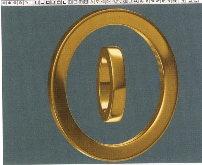
10. Select "View" > "Shadow Map" from the menu bar to inspect the shadow effects
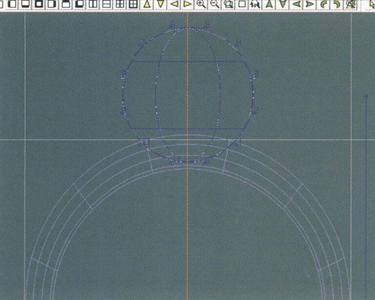
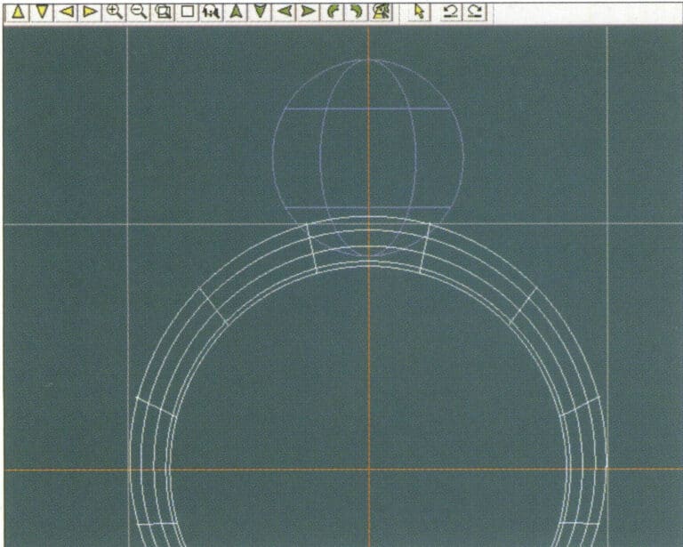
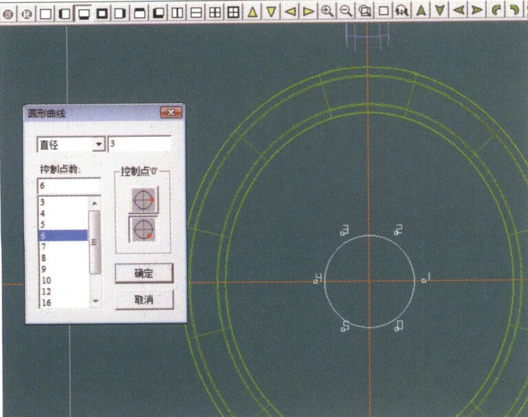
11. Select "Curve" > "Circular Curve" from the menu bar, enter the relevant values in the "Circular Curve" dialog box as auxiliary lines, and confirm
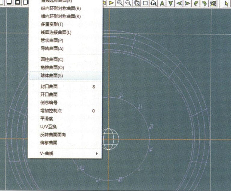
12. Select "Surface" > "Spherical Surface" from the menu bar
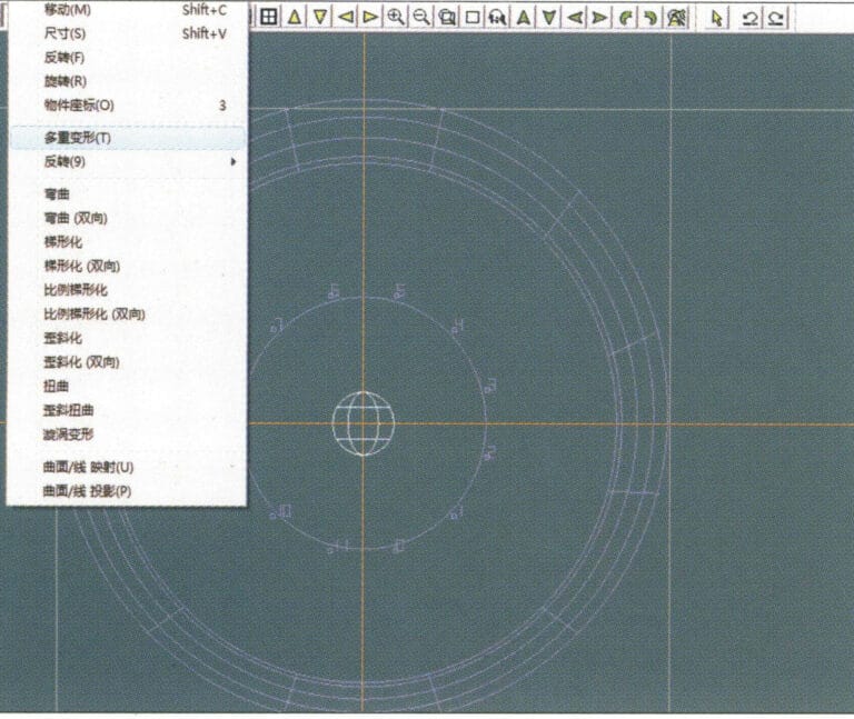
13. Select "Deformation" > "Multiple Deformation" from the menu bar to enlarge the sphere
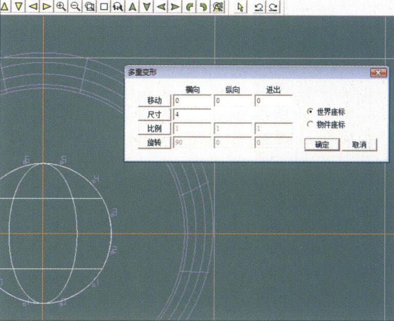
14. Entre en el cuadro de diálogo "Deformación múltiple", introduzca los valores correspondientes para ampliar la esfera a la anchura de las directrices y confirme
15. Select "Edit" > "Move" from the menu bar to move both the sphere and the auxiliary line simultaneously
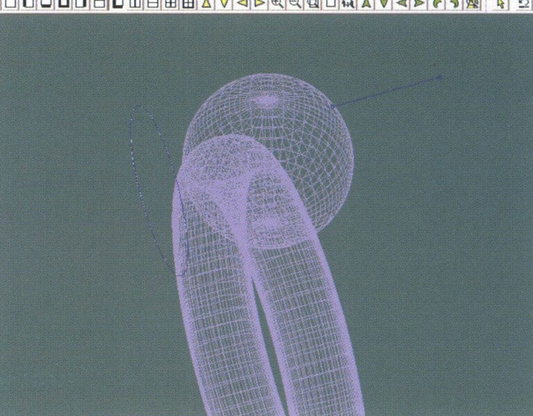
16. Select "Edit" > "Move" from the menu bar to remove the guidelines
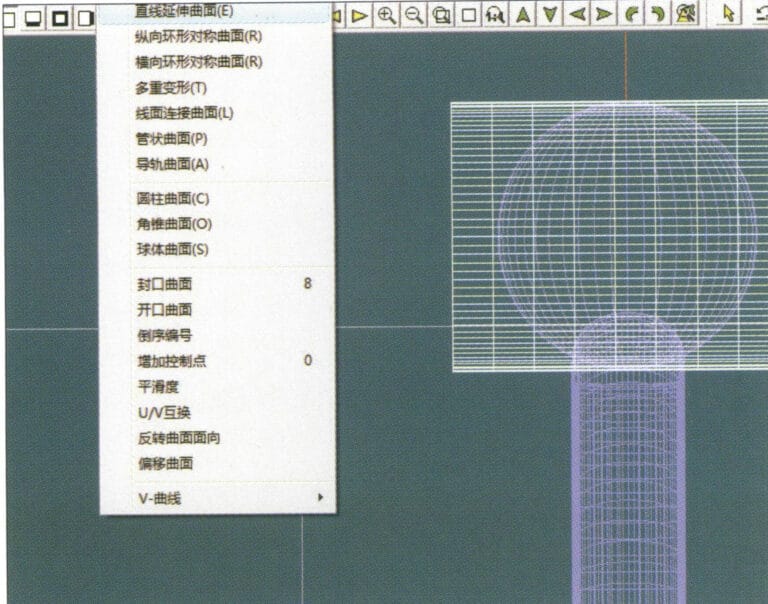
17. Select "Surface" > "Straight Line Extend Surface" from the menu bar to extend the auxiliary line into an auxiliary surface
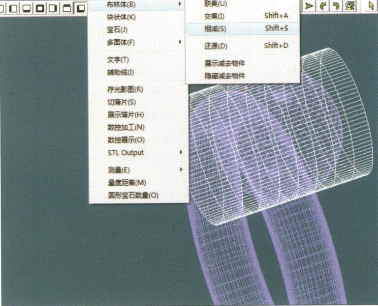
18. Select "Miscellaneous" > "Boolean" > "Subtract" from the menu bar to subtract the corresponding parts of the auxiliary surface ring
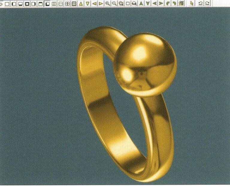
19. Select "View" > "Shadow Map" from the menu bar to inspect the shadow effects
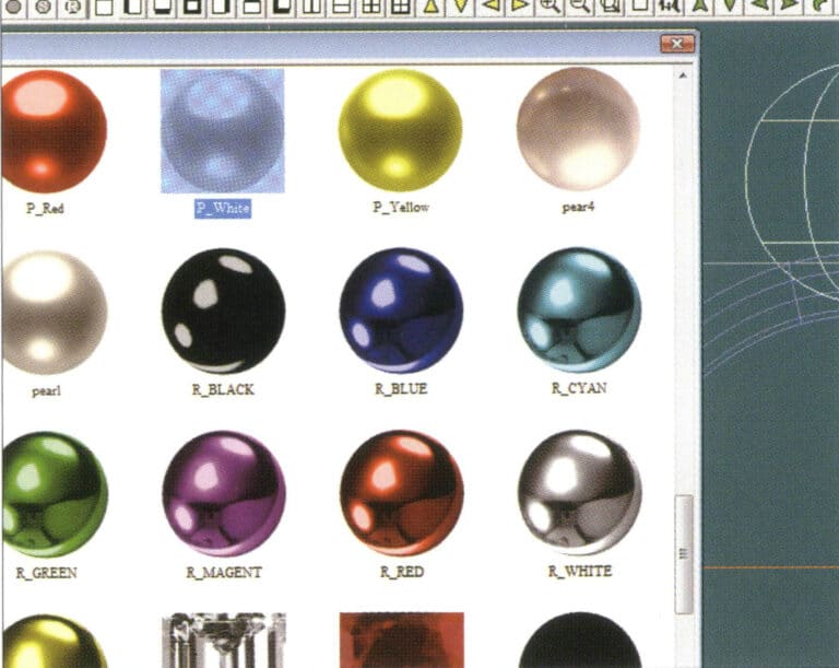
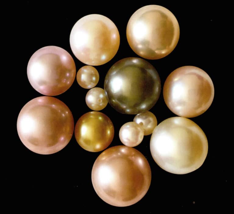
20. Select the sphere, go to the menu bar and choose "Edit" > "Materials", enter the "Materials" dialog box, select the white pearl material and confirm
21. Select the ring band, then choose "Edit" > "Materials" from the menu bar
22. Entre en el cuadro de diálogo "Materiales", seleccione el material adecuado y confirme
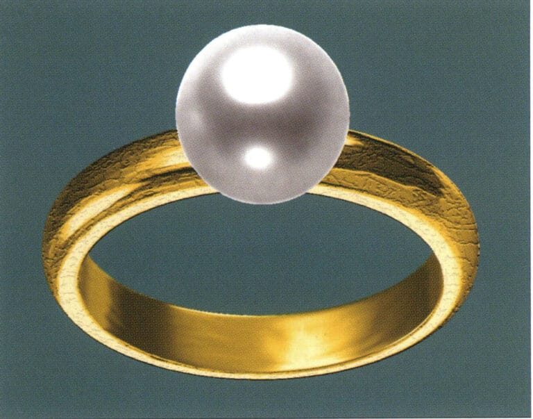
23. Select "View" > "Shadow Map" from the menu bar to examine the light and shadow effects
24. Select "File" > "Save As" from the menu bar to save the file

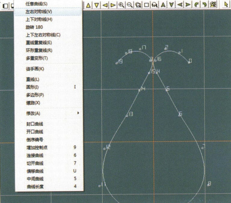
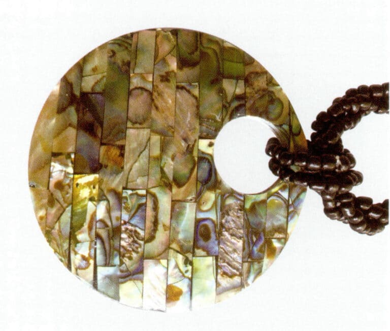
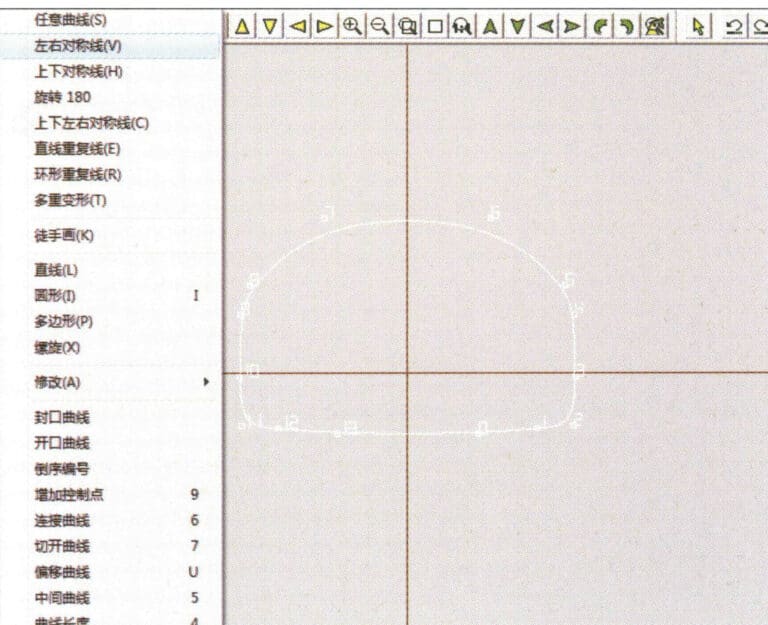
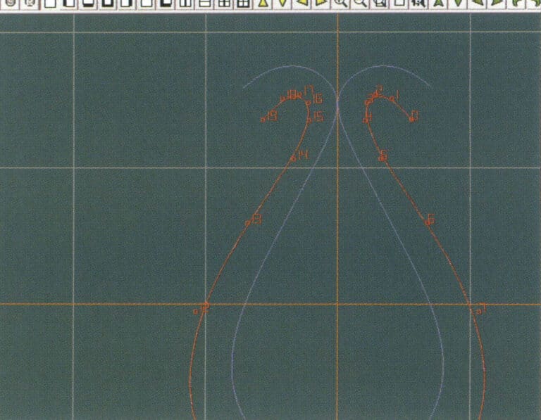
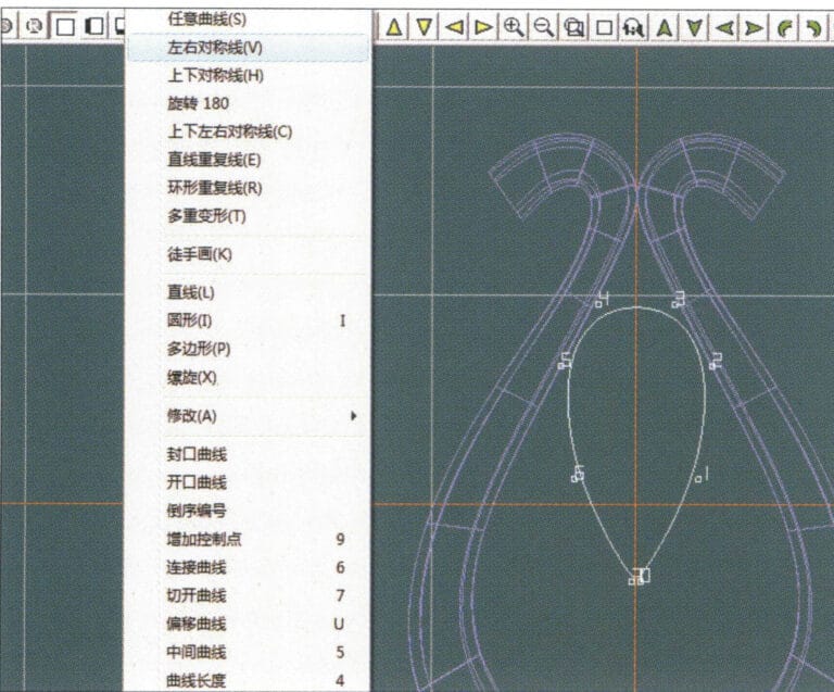
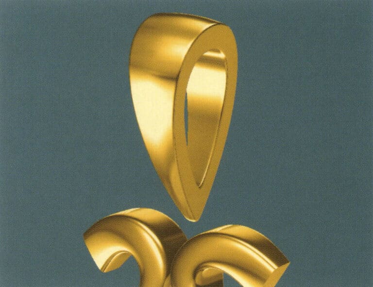
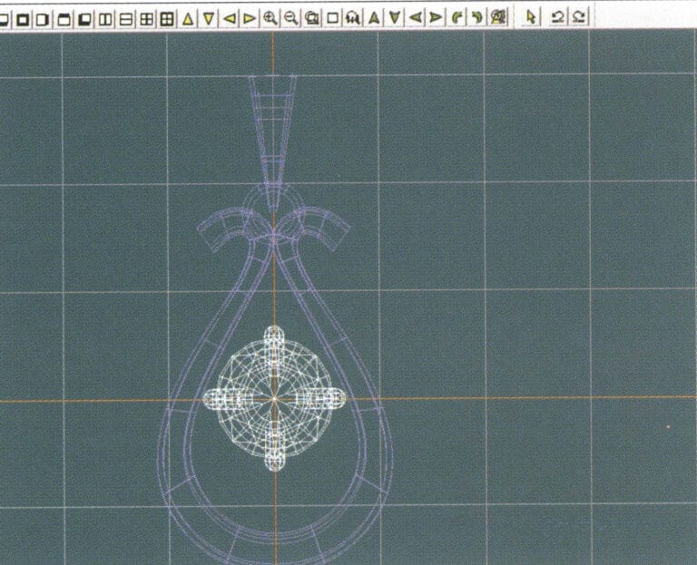
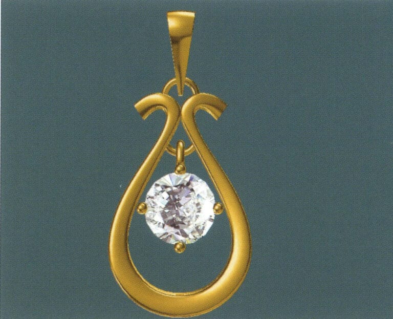
1. Create a new file in JewelCAD, select "Curve" > "Left-Right Symmetrical Line" from the menu bar, and draw the inner contour line of the pendant
2. Select "Curve" > "Left-Right Symmetrical Line" from the menu bar to draw the outer contour line of the pendant (note that the control points of the inner contour line and the outer contour line should have the same direction and quantity).
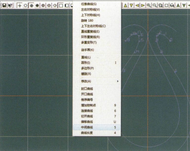
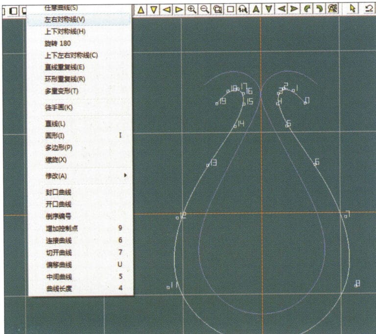
3. Select "Curve" > "Middle Curve" from the menu bar
4. Seleccione dos curvas para crear la curva central. En primer lugar, seleccione la línea de contorno exterior
5. Seleccione dos curvas para crear la curva central y, a continuación, seleccione la línea de contorno interior
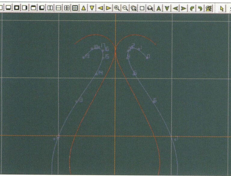
6. Ver las curvas intermedias ya creadas
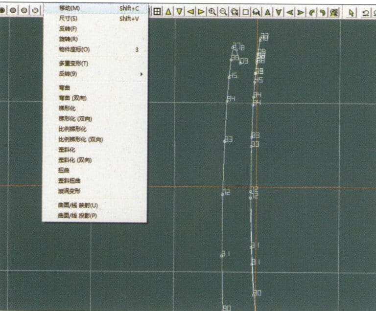
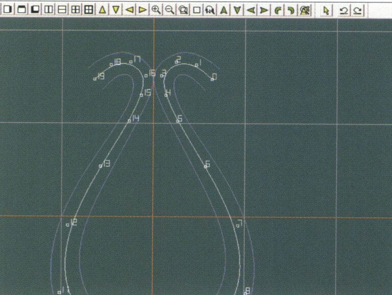
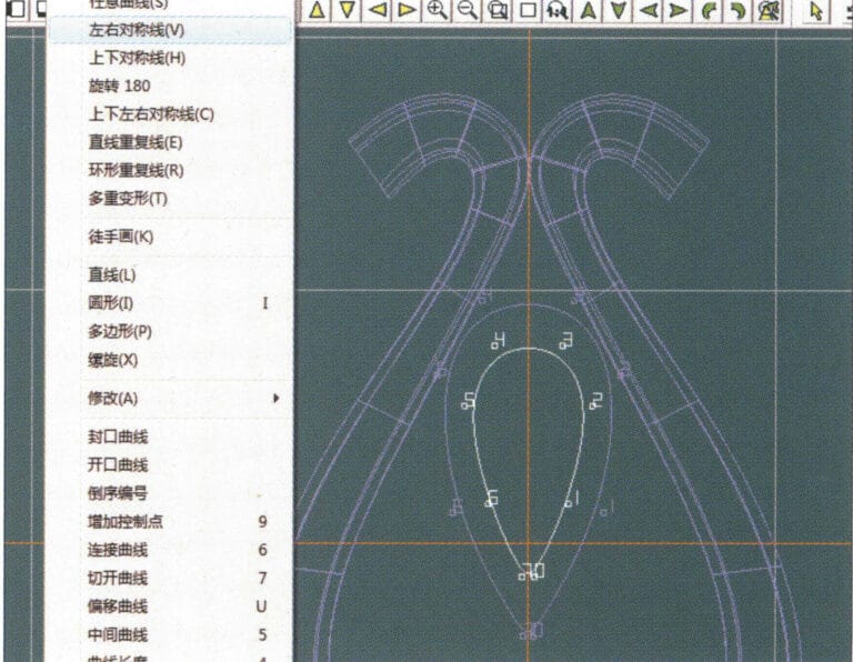
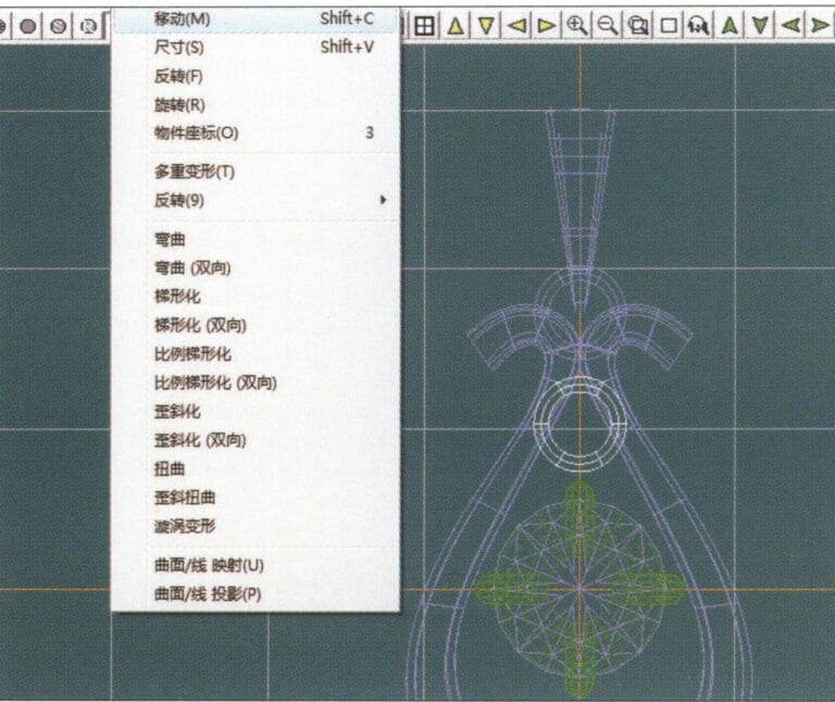
7. Select "Deformation" > "Move" from the menu bar to move the CV and the CV of the contour line
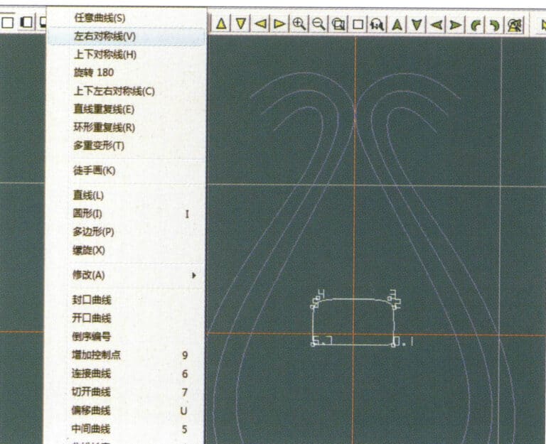
8. Select "Curve" > "Left-Right Symmetry Line" from the menu bar to create a cross-section
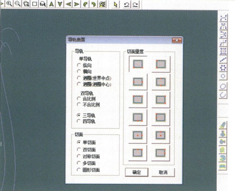
9. Select "Surface" > "Rail Surface" from the menu bar, enter the "Rail Surface" dialog box to select the relevant options, and confirm; select a curve as the left curve, starting from the left curve in a clockwise direction, left-click on the curve as the rail, and then select another curve as the section of the rail surface
10. Select "View" > "Shadow Map" from the menu bar to inspect the shadow effects
11. Select "Curve" > "Left-Right Symmetry Line" from the menu bar to draw the outer contour line of the seed-shaped toggle
12. Select "Curve" > "Left-Right Symmetry Line" from the menu bar to draw the inner contour line of the seed-shaped toggle
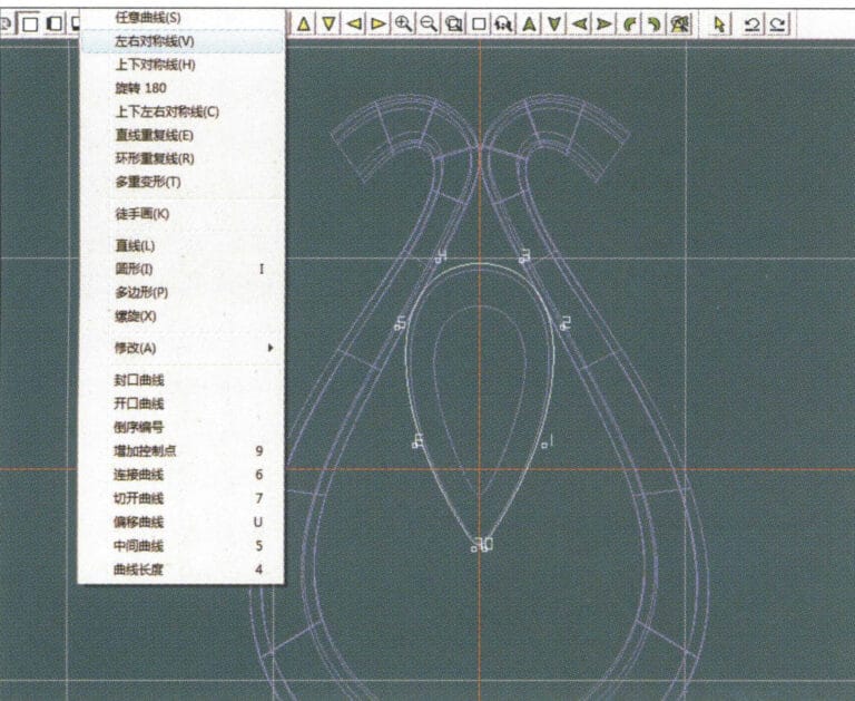
13. Select "Curve" > "Left-Right Symmetry Line" from the menu bar, and draw the lower dark line of the center of the seed-shaped toggle
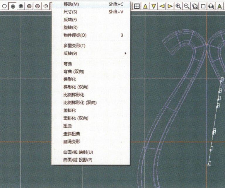
14. Select "Deformation" > "Move" from the menu bar to move the seed-shaped toggle CV
15. Select "Copy" > "Copy Left and Right" from the menu bar to copy the curve of the seed-shaped toggle
16. Select "Deformation" > "Move" from the menu bar to move the melon seed buckle curve
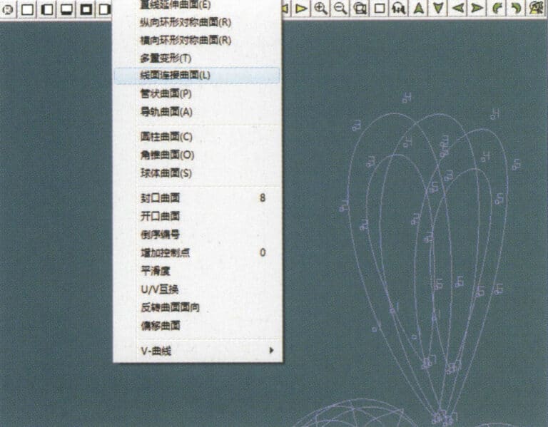
17. Select "Surface" > "Line-Surface Connection Surface" from the menu bar, and select the curve/surface in a clockwise direction to create a line-surface connection surface, then select "Curve" > "Closed Surface" from the menu bar
18. Select "View" > "Shadow Map" from the menu bar to examine the shadow effects
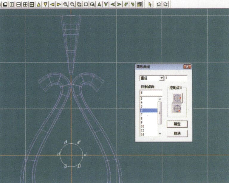
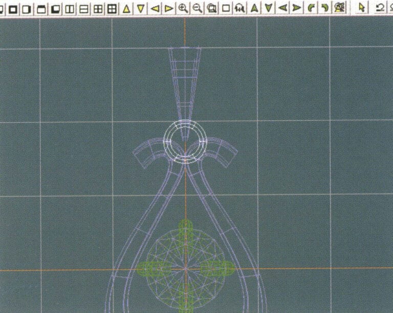
19. Select "Curve" > "Circular Curve" from the menu bar, enter the relevant values and confirm

20. Select "Surface" > "Tubular Surface" from the menu bar
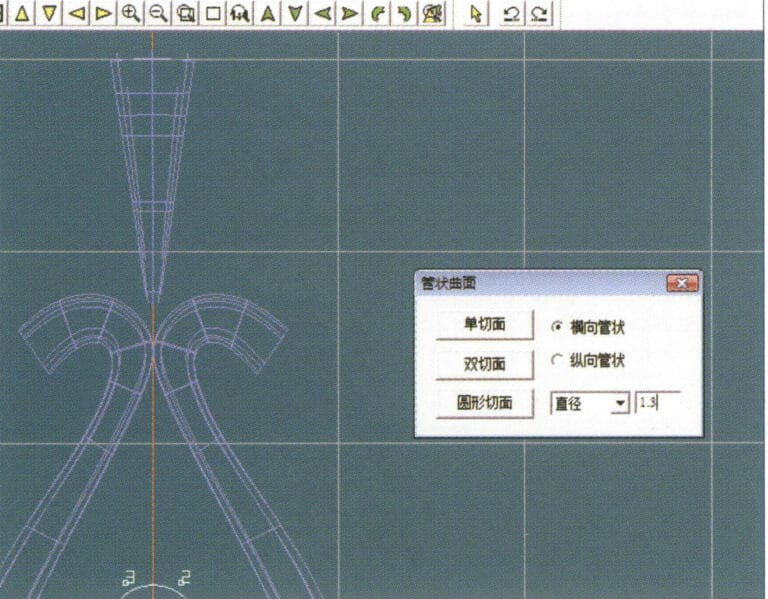
21. Entre en el cuadro de diálogo "Superficie tubular", introduzca los valores correspondientes, haga clic en la sección circular y confirme
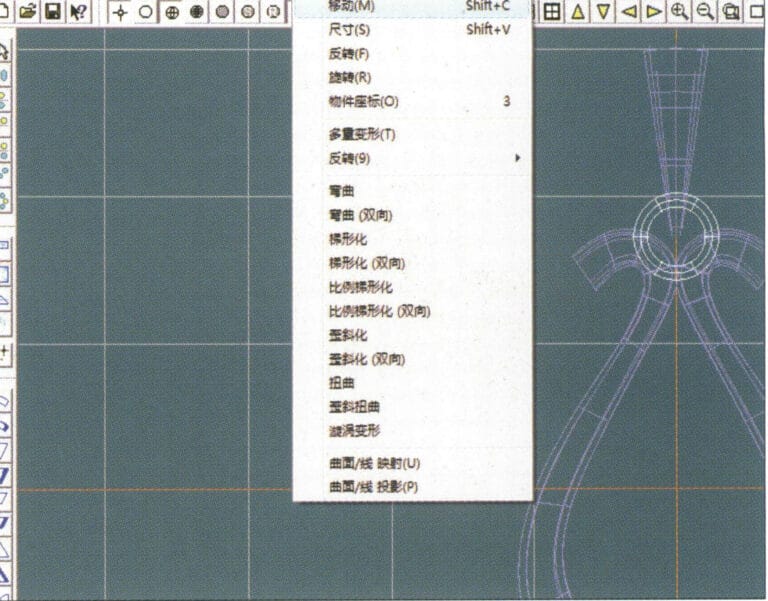
22. Select "Deformation" > "Move" from the menu bar to move the ring buckle

23. Select "File" > "Insert File" from the menu bar
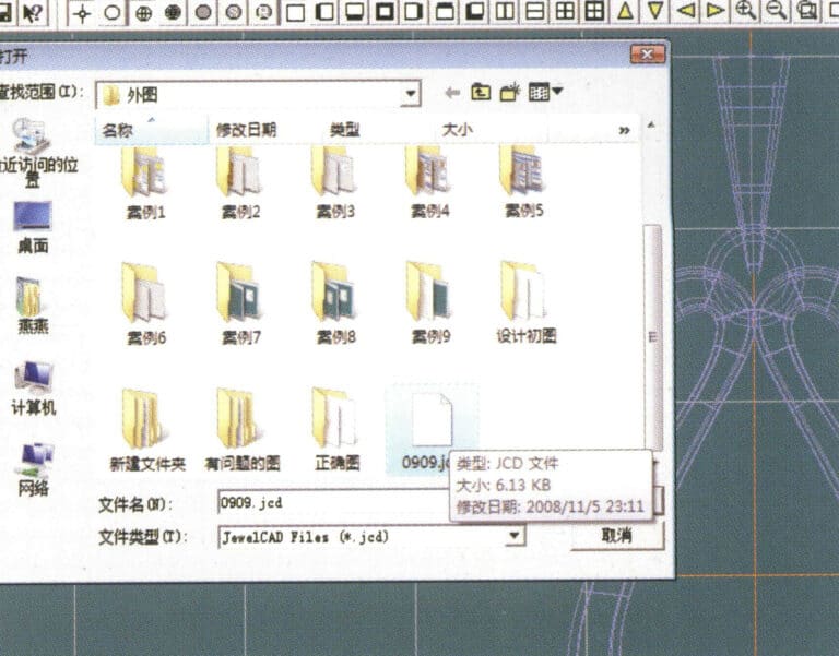
24. Entre en el cuadro de diálogo "Insertar archivo", seleccione el documento deseado y confirme
25. Ver el archivo insertado - Gemstone
26. Select "Copy" > "Copy Up and Down" from the menu bar to copy the selected toggle
27. Select "Deformation" > "Move" from the menu bar to move the horizontal ring toggle
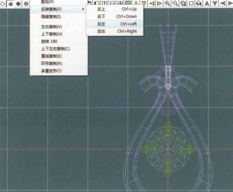
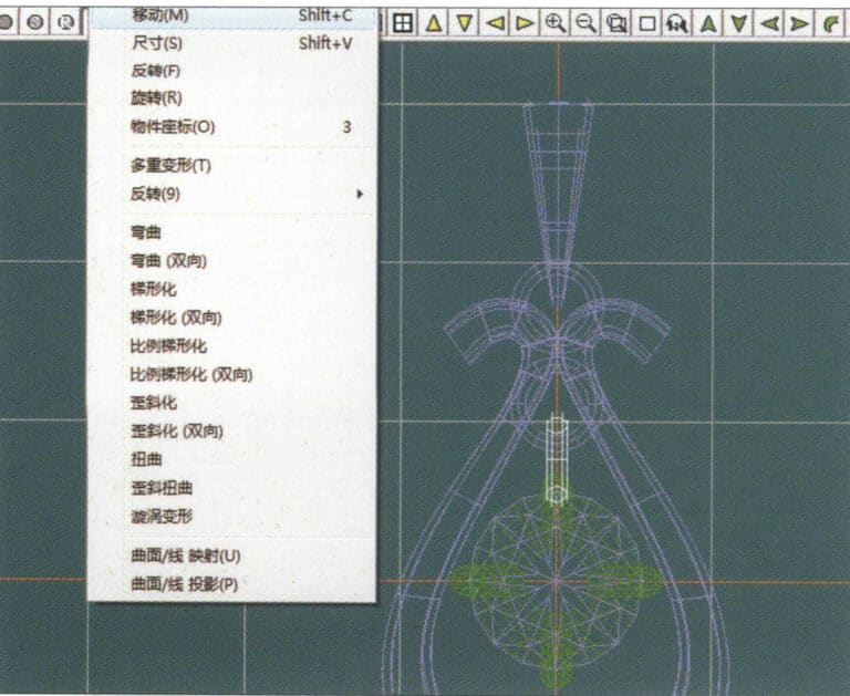
28. Select "Copy" > "Reverse Copy" > "Reverse Left" from the menu bar to create a vertical ring toggle
29. Select "Deformation" > "Move" from the menu bar to move the horizontal ring toggle
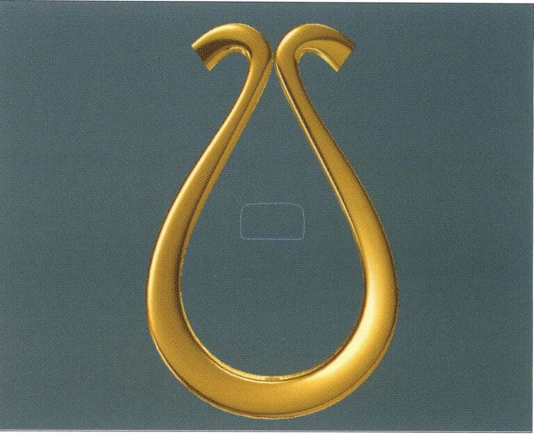
30. Select "View" > "Shadow Map" from the menu bar to examine the light and shadow effects
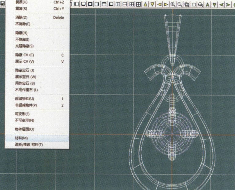
31. Select "Edit" > "Materials" from the menu bar to modify the materials of the selected object
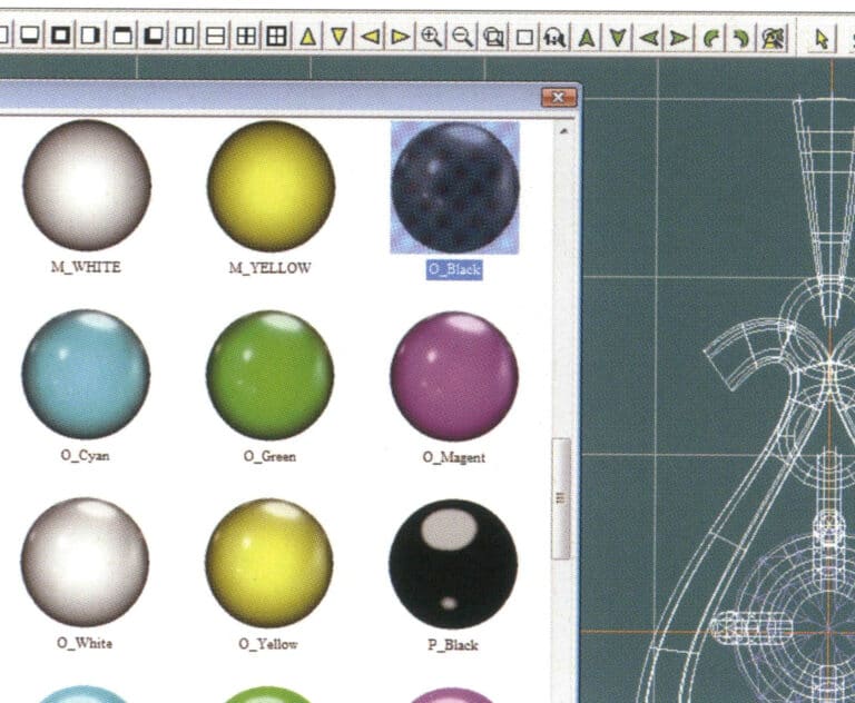
32. Entre en el cuadro de diálogo "Materiales", seleccione oro negro y confirme
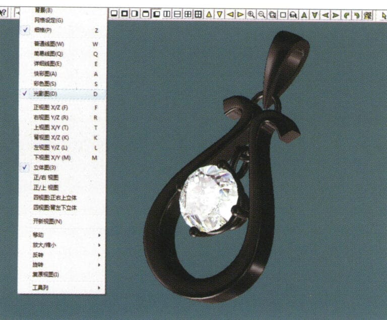
33. Select "View" > "Shadow Map" from the menu bar to inspect the shadow effects
34. Select "File" > "Save As" from the menu bar to save the file
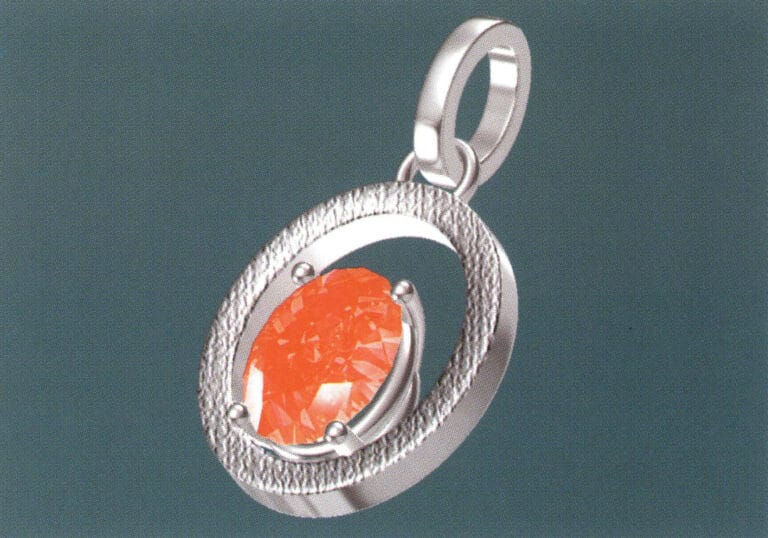
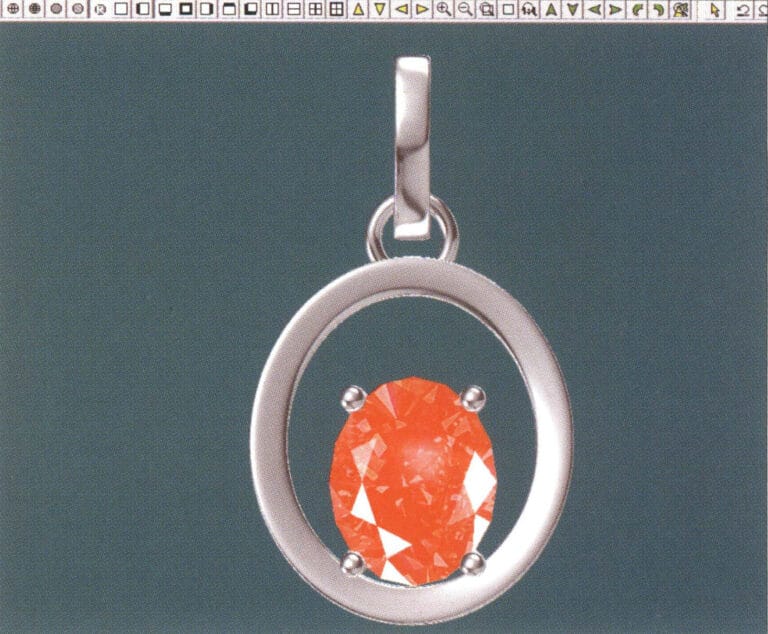
1. Create a new file in JewelCAD, select "Curve" > "Circular Curve" from the menu bar, enter the relevant values in the "Circular Curve" dialog box as the inner auxiliary line, and confirm

2. Select "Curve" > "Circular Curve" from the menu bar, enter the relevant values in the "Circular Curve" dialog box as the external auxiliary line, and confirm
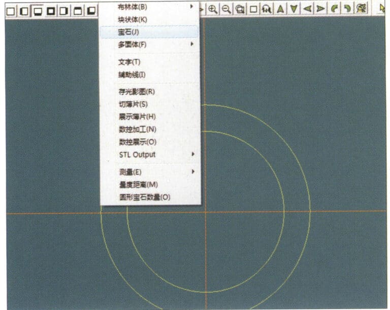
3. Select "Miscellaneous" > "Gemstones" from the menu bar
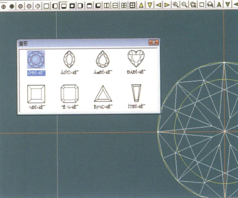
4. Entre en el cuadro de diálogo "Gema", seleccione las gemas correspondientes y confirme
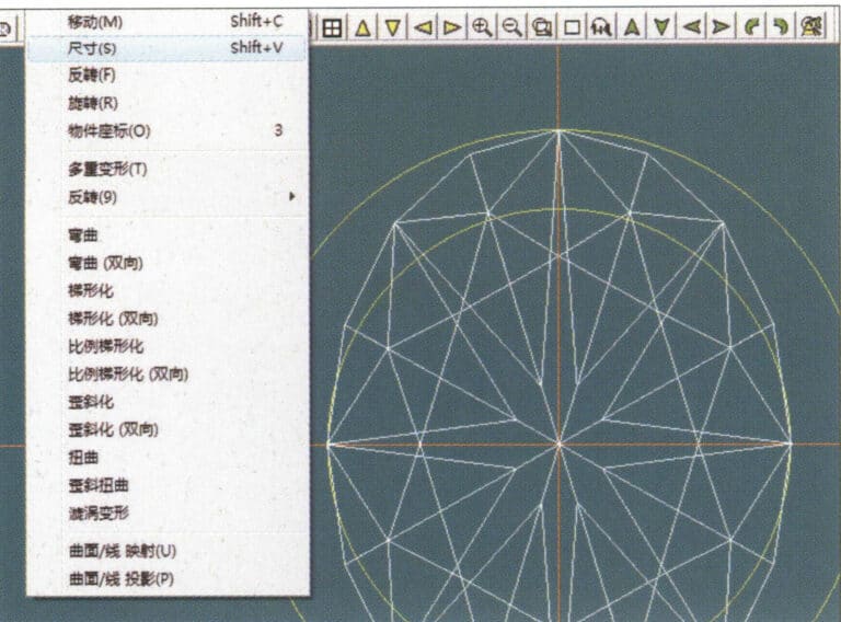
5. Select "Deformation" > "Size" from the menu bar to change the round gemstone into an oval gemstone
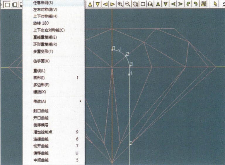
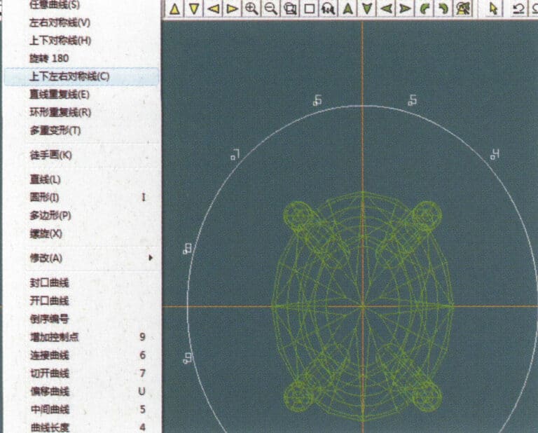
6. Select "Curve" > "Freeform Curve" from the menu bar to draw a claw-shaped guideline
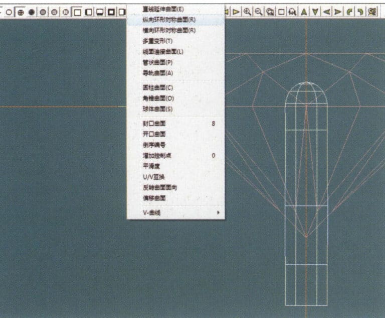
7. Select "Surface" > "Longitudinal Circular Symmetrical Surface" from the menu bar, and draw a claw shape
8. Select "Copy" > "Copy Left and Right" from the menu bar to copy the claw shape
9. Select "Copy" > "Copy Up and Down" from the menu bar to copy the claw shape again
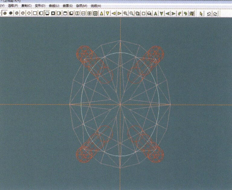
10. Select "Deformation" > "Size" from the menu bar to change the circular guideline to an elliptical guideline
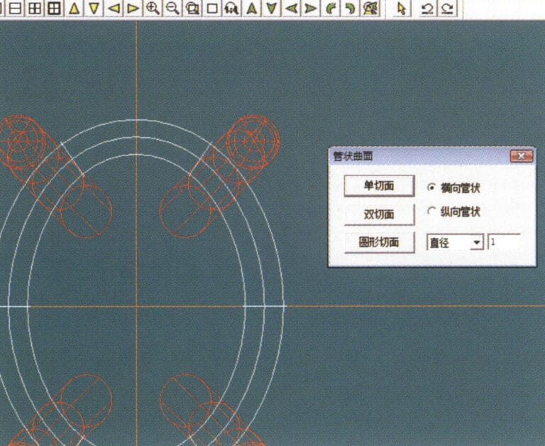
11. Select "Curved Surface" > "Tubular Surface" from the menu bar, enter the relevant values in the "Tubular Surface" dialog box and confirm
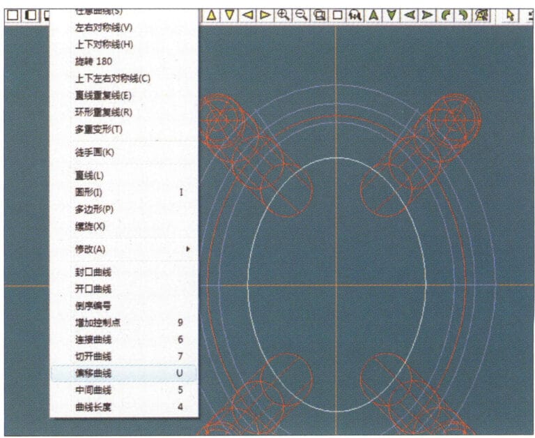
12. Select "Curve" > "Offset Curve" from the menu bar
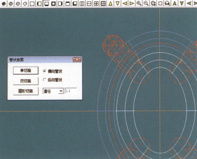
13. Select "Surface" > "Tubular Surface" from the menu bar, enter the relevant values and confirm
14. Select "View" > "Shadow Map" from the menu bar to examine the shadow effects and inspect the setting
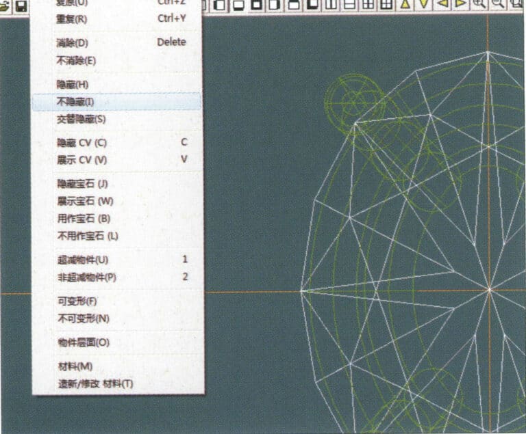
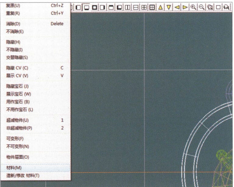
15. Select "Edit" > "Unhide" from the menu bar to display the hidden gems
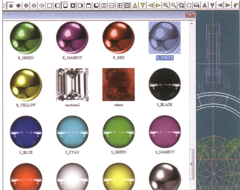
16. Select "Edit" > "Materials" from the menu bar
17. Entre en el cuadro de diálogo "Materiales", seleccione ruby y confirme
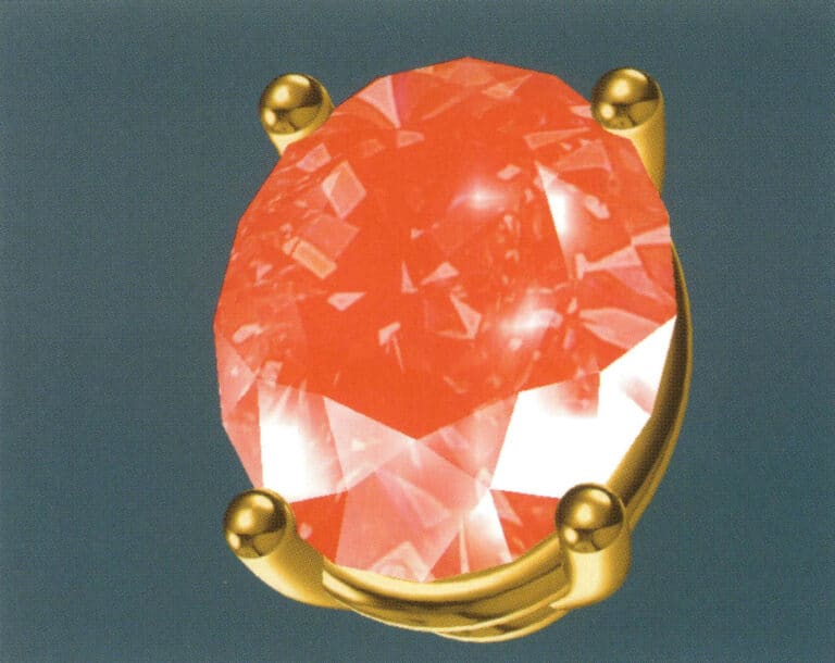
18. Select "View" > "Shadow Map" from the menu bar to examine the shadow effects
19. Select "Curve" > "Vertical and Horizontal Symmetry Line" from the menu bar as the auxiliary line for the outer circle
20. Select "Curve" > "Offset Curve" from the menu bar
21. Entre en el cuadro de diálogo "Curva de desplazamiento", introduzca los valores correspondientes como líneas auxiliares para el círculo interior y confirme
22. Select "Curve" > "Left-Right Symmetrical Line" from the menu bar as the cross-section of the coil
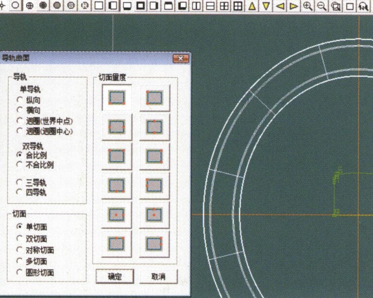
23. Select "Curved Surface" > "Rail Surface" from the menu bar to enter the "Rail Surface" dialog box, select the relevant options and confirm
24. Select "Curve" > "Circular Curve" from the menu bar, enter the relevant values in the "Circular Curve" dialog box, and confirm; left-click on one curve as the left guide curve, click on another curve as the right guide rail, and then select the coil cross-section as the cross-section of the guide rail surface; once completed, it serves as the auxiliary line for the outer circle of the chain threading position

25. After completing the outer auxiliary lines for the chain position, select "Curve" > "Offset Curve" from the menu bar
26. Entre en el cuadro de diálogo "Curva de desplazamiento", introduzca los valores correspondientes y confirme
27. Select "Surface" > "Rail Surface" from the menu bar to enter the "Rail Surface" dialog box, select the relevant options and confirm, left-click on a curve to set it as the left rail curve, click on another curve to set it as the right rail, and then select the coil cross-section as the cross-section of the rail surface
28. Select "View" > "Shadow Map" from the menu bar to inspect the shadow effects
29. Select "Curve" > "Circular Curve" from the menu bar, enter the relevant values and confirm
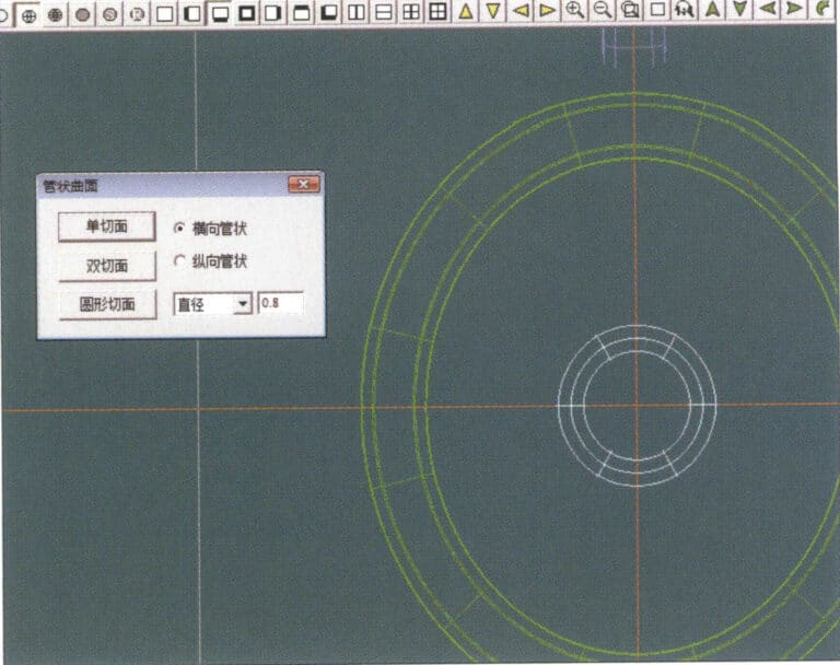
30. Select "Curved Surface" > "Tubular Surface" from the menu bar, enter the relevant values and confirm
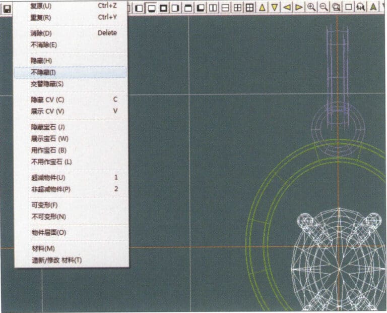
31. Select "Edit" > "Unhide" from the menu bar to display the hidden objects
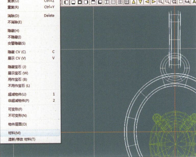
32. Select "Edit" > "Materials" from the menu bar
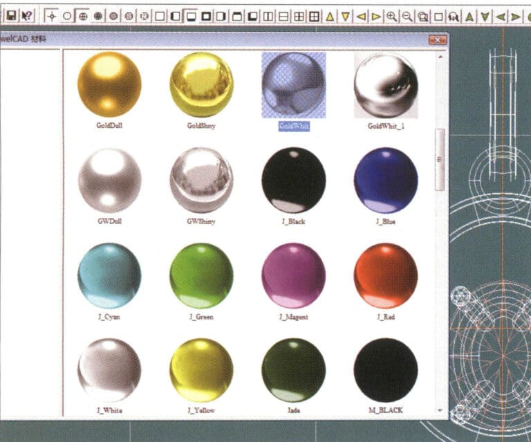
33. Entre en el cuadro de diálogo "Materiales", seleccione los materiales correspondientes y confirme
34. Select "View" > "Shadow Map" from the menu bar to inspect the shadow effects
35. Select "Edit" > "Materials" from the menu bar
36. Entre en el cuadro de diálogo "Materiales", seleccione los materiales de textura correspondientes y confirme
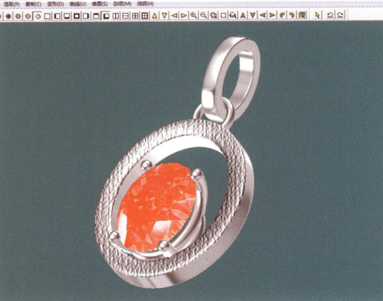
37. Select "View" > "Shadow Map" from the menu bar to inspect the shadow effects
38. Select "File" > "Save As" from the menu bar to save the file