Ένας ολοκληρωμένος οδηγός για τα κοσμήματα από κράμα χαλκού και την τεχνολογία παραγωγής
Mastering Copper Alloy Jewelry: Techniques, Materials & Trends
Εισαγωγή:
This article dives into the fascinating world of copper alloy jewelry and its production methods. It’s divided into four main sections:
1. Overview: Learn about copper’s history, properties, and its role in jewelry making. Copper alloys like brass, bronze, and cupronickel are highlighted for their versatility and beauty.
2. Pure Copper and High Copper Alloys: Discover the different types of pure copper, such as oxygen-free copper and micro-alloyed copper, and how they’re used in jewelry for their durability and unique colors.
3. Copper Alloys: Explore popular alloys like brass (copper-zinc), bronze (copper-tin), and cupronickel (copper-nickel), each offering distinct colors, corrosion resistance, and workability for crafting stunning pieces.
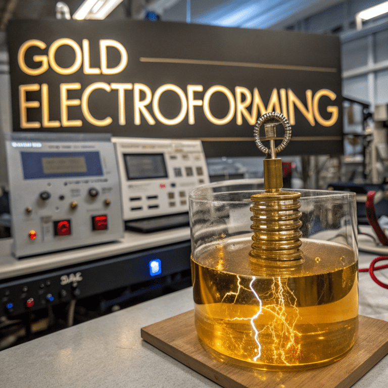
4. Production Techniques: Get insights into advanced methods like lost-wax casting, stamping, and electroforming, along with surface treatments such as gold plating and polishing to create high-quality, eye-catching jewelry.

κόκκινο χάλκινο θεραπευτικό βραχιόλι
Πίνακας περιεχομένων
Ενότητα Ι Επισκόπηση
Copper and copper alloys can be divided into two main categories based on the production process: processing and casting. All alloys with a Z prefix in their designation belong to casting alloys. In contrast, the designations for processed copper and copper alloys in China are traditionally classified into four categories: purple, yellow, green, and white. Among them, purple copper alloys are all supplied in processed form. The T prefix represents the code for purple copper. The first letter H of the pinyin for yellow represents yellow copper. Similarly, Q represents bronze, B represents cupronickel, and the subsequent chemical element symbols and numbers represent the nominal weight percentage of the added elements.
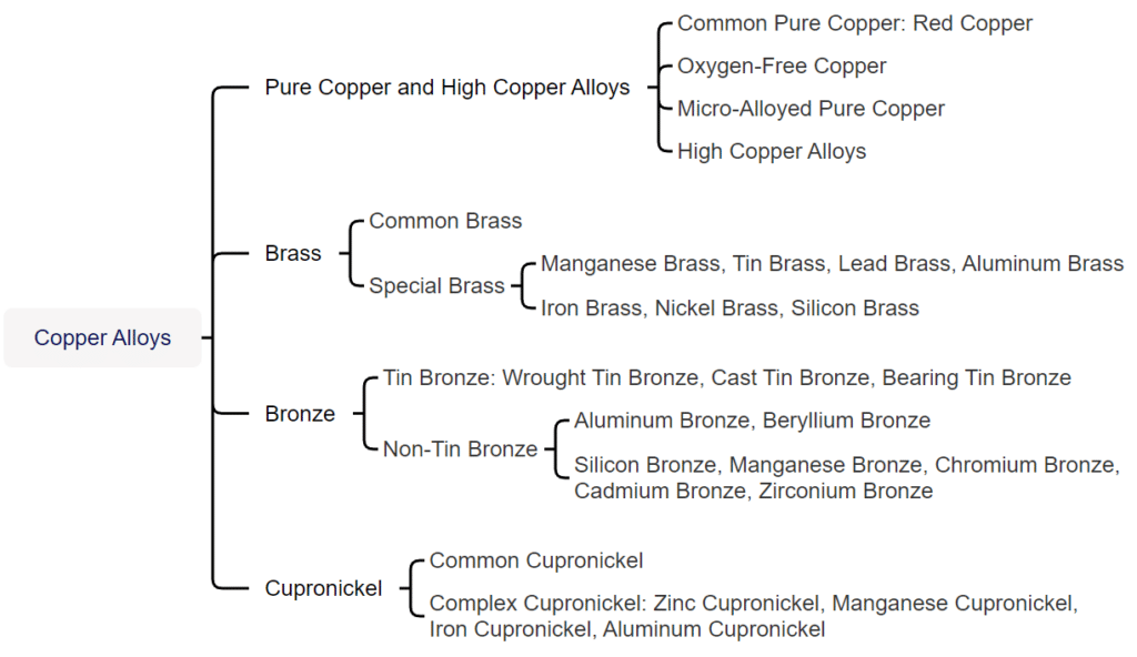
Copper and copper alloys can be divided into two categories based on function: general purpose and special purpose. Copper alloys used for jewelry belong to a type of special copper alloy with specific requirements for hue, corrosion resistance, casting performance, machining performance, welding performance, and coloring performance. The main copper and copper alloys used in jewelry production include pure copper and high-copper alloys, tin bronze, brass, zinc cupronickel, imitation gold-copper alloys, and imitation silver-copper alloys.
Section II Pure Copper and High Copper Alloys
1. Pure Popper and its Properties
Pure copper can be divided into several categories based on chemical composition: ordinary pure copper, oxygen-free pure copper, and micro-alloyed pure copper.
(1) Ordinary Pure Copper
Ordinary pure copper has a copper mass fraction of not less than 99.7%, with very little impurity content, and has a purplish-red appearance. Hence, it is also called purple copper. The main grades of ordinary pure copper are T1, T2, and T3. According to GB/T 5231-2001, the commonly used chemical composition of ordinary pure copper is shown in Table 2-1.
Table 2-1 Common Chemical Composition of Ordinary Pure Copper (Quality fraction unit: %)
| Βαθμός | Cu+Ag | P | Bi | Sb | Όπως | Fe | Ni | Pb | Sn | S | Zn | O | Sum of impurities |
| Not less than | Not more than | ||||||||||||
| T1 | 99. 95 | 0.001 | 0.001 | 0.002 | 0.002 | 0.005 | 0.002 | 0.003 | 0.002 | 0.005 | 0.005 | 0.02 | 0.05 |
| T2 | 99. 90 | - | 0.001 | 0.002 | 0.002 | 0.005 | - | 0.005 | - | 0.005 | - | - | 0.1 |
| T3 | 99. 70 | - | 0.002 | - | - | - | - | 0.01 | - | - | - | - | 0.3 |
| (Liu Ping, 2007; Wang Biwen, 2007; Tian Rongzhang and Wang Shitang, 2002; National Nonferrous Metals Standardization Technical Committee, 2012) | |||||||||||||
Table 2-2 Physical Properties of Ordinary Pure Copper
| Performance Name | Numerical value | Performance Name | Numerical value |
|---|---|---|---|
| Lattice type | Κυβικός με κέντρο το πρόσωπο | Electronic configuration | Is2 2s2 2P6 3s2 3P6 3d10 4s1 |
| Atomic weight | 63.54 | Resistivity | 0. 016 73 Ω·m |
| Ατομική ακτίνα | 0. 157nm | Thermal conductivity(273-373K) | 399W/(m • K) |
| Ionic radius | 0. 073nm | Temperature coefficient of resistance | 0. 003 93/℃ |
| Πυκνότητα | 8. 92g/cm3 | Μαγνητική επιδεκτικότητα | -0. 86 X 10-3/kg |
| Σημείο τήξης | 1 083. 4℃ | Ειδική θερμοχωρητικότητα | 0.39X 10³J/(kg •℃) |
| Σημείο βρασμού | 2 567℃ | Linear expansion coefficient | 17. 6X10⁻⁶/℃ |
| (Liu Ping, 2007; Wang Biwen, 2007; Tian Rongzhang and Wang Shitang, 2002; National Nonferrous Metals Standardization Technical Committee, 2012) | |||
Copper is a relatively inactive heavy metal with good corrosion resistance. It is stable in dry air at room temperature and can produce black copper oxide when heated. Red cuprous oxide is formed if it is further calcined at high temperatures. After being placed in humid air for a long time, a layer of verdigris (basic copper carbonate) slowly forms on the surface of the copper. Verdigris can prevent further corrosion of the metal; its composition is variable, and it is soluble in nitric acid and hot concentrated sulfuric acid, slightly soluble in hydrochloric acid, and easily corroded by alkalis. In the electrochemical (metal activity series), copper ranks after hydrogen, so it cannot displace hydrogen from dilute acids. However, copper can slowly dissolve in the air in these dilute acids. Copper can react with heated concentrated hydrochloric acid and is easily soluble in nitric acid and oxidizing acids like hot concentrated sulfuric acid. Copper can also react with ferric chloride. In the jewelry industry, ferric chloride solution is often used to etch copper to create various decorative textures and patterns.
The mechanical properties of ordinary pure copper are closely related to its state, as shown in Table 2-3.
Table 2-3 Mechanical Properties of Ordinary Pure Copper in Different States
| Επιδόσεις | Processing Copper | Return copper | Casting copper |
|---|---|---|---|
| Elastic limit/ MPa | 280 ~ 300 | 20 ~ 50 | - |
| Yield point / MPa | 340 ~ 350 | 50 ~ 70 | - |
| Tensile strength/ MPa | 370 ~ 420 | 220 ~ 240 | 170 |
| Elongation rate / % | 4 ~ 6 | 45 ~ 50 | - |
| Shrinkage rate/ % | 35 ~ 45 | 65 ~ 75 | - |
| Brinell hardness / HB | 1 100 ~ 1 300 | 350 ~ 450 | 400 |
| Shear strength/ MPa | 210 | 150 | - |
| Impact toughness/J·cm-2 | - | 16 ~ 18 | - |
| Compressive strength / MPa | - | - | 1570 |
| Upsetting ratio/ % | - | - | 65 |
| (Liu Ping, 2007; Wang Biwen, 2007; Tian Rongzhang and Wang Shitang, 2002; National Nonferrous Metals Standardization Technical Committee, 2012) | |||
(2) Oxygen-free Pure Copper
Oxygen-free pure copper is pure copper with significantly reduced oxygen content achieved through various refining methods. According to GB/T5231, oxygen-free copper is divided into several grades: zero, one, and two grades of oxygen-free copper, with the corresponding copper and oxygen content shown in Table 2-4. Oxygen-free copper does not exhibit hydrogen embrittlement and has high electrical conductivity, good processing, welding, corrosion resistance, and low-temperature performance. Oxygen-free copper is generally preferred when preparing gold and silver alloy filler material to reduce impurities in the joint.
Table 2-4 Requirements for Oxygen Content in Oxygen-Free Copper
| Grades | Κωδικός | Copper + silver ≥ | Oxygen≯ |
|---|---|---|---|
| No. 0 oxygen-free copper | TU0 | 99. 99 | 0. 0005 |
| No. 1 oxygen-free copper | 99. 97 | 0.002 | |
| No. 2 oxygen-free copper | TU2 | 99. 95 | 0.003 |
| (National Nonferrous Metals Standardization Technical Committee, 2012) | |||
(3) Micro-alloyed Pure Copper
Micro-alloyed pure copper uses alloying elements such as chromium, zirconium, silver, aluminum, phosphorus, sulfur, and antimony, which can effectively improve the performance of pure copper when added in trace amounts. Micro-alloyed pure copper has multiple grades, such as TUAg0.06, TUAg0.05, TUAg0.08, TUAg0.1, TUAg0.2, TUAg0.3, TUA10.12, TUZr0.15, TAg0.15, TAg0.1-0.01, TP3, TP4, TTe0.3, TTe0.5-0.008, TTe0.5-0.02, TZr0.15, etc. Taking zirconium micro-alloyed pure copper as an example, the table 2-5 shows its mechanical properties, which are significantly improved compared to ordinary pure copper, and the softening temperature has reached 500℃.
Table 2-5 Mechanical Properties of Zirconium – Micro-alloyed Pure Copper QZr0.2
| Material State | Αντοχή σε εφελκυσμό/MPa | Yield strength/MPa | Stretch rate/% | Vickers hardness/HV | Elastic modulus/GPa |
|---|---|---|---|---|---|
| Quenched at 980℃, aged at 500℃ for 1 hour | 260 | 134 | 19. 0 | 83 | - |
| 900 ℃ quenching, 500 ℃ aging 1 hour | 230 | 160 | 40. 0 | - | - |
| 900C heating 30 minutes quenching, cold working 90% | 450 | 385 | 3.0 | 137 | 136 |
| 980℃ heating 1 hour, 90% cold working, 400℃ aging 1 hour | 492 | 428 | 10.0 | 150 | 133 |
| 900℃ quenching, cold working 90%, 400℃ aging 1 hour | 470 | 430 | 10.0 | 140 | |
| (Liu Ping, 2007; Wang, B., 2007; Tian, R. Z. and Wang, S. T., 2002; National Technical Committee for Standardization of Nonferrous Metals, 2012) | |||||
2. High Copper Alloy
High copper alloys, also known as low-alloy copper, refer to copper alloys that contain one or several trace alloying elements to achieve certain special properties. The copper content is 99.3%~96% and cannot be classified into any copper alloy group for processed products. For cast products, the copper content should be greater than 94%, which can be added to obtain certain characteristics.
Solid solution strengthening and precipitation strengthening are important strengthening methods for copper alloys. Common alloying elements include Cr, Zr, Ti, Si, Mg, Te, etc. Their solubility in copper decreases sharply with decreasing temperature. These elements precipitate in the solid state as pure substances or metallic compounds, resulting in solid solution strengthening and precipitation strengthening. The American foundry’s high copper alloy grades include C81300~C19600 and the processed high copper alloy grades ranging from C16200 to C19600. In the newly revised GB/T5231-2012 “Grades and Chemical Composition of Processed Copper and Copper Alloys,” China lists high copper alloy grades such as TTi3.0 – 0.2, TNi2.4 – 0.6 – 0.5, TPb1.0, TC r1 – 0.18, TCr0.3 – 0.3, TCr0.5 – 0.1, TCr0.7, TCr0.8, TCr1 – 0.15.
3. Process Performance of Pure Copper and High Copper Alloys
(1) Smelting Process
Pure copper and high-copper alloys are prone to absorb hydrogen and oxygen during the casting process, leading to porosity and oxidation inclusions, affecting the castings’ surface quality. The content of hydrogen and oxygen is closely related to the temperature of the material. Table 2-6 shows the hydrogen solubility in copper at different temperatures.
Table 2-6 Solubility of Hydrogen in Copper at 0.1 MPa (Nie Xiaowu, 2006)
| Θερμοκρασία /℃ | 400 | 500 | 600 | 700 | 800 | 900 | 1000 | 1100 | 1200 | 1300 | 1400 | 1500 |
|---|---|---|---|---|---|---|---|---|---|---|---|---|
| Solubility /cm3 • (100g copper)-1 | 0.06 | 0.16 | 0. 3 | 0.49 | 0. 72 | 1.08 | 1.58 | 6.3 | 8. 1 | 10.9 | 11.8 | 13.6 |
Oxygen does not dissolve in copper and forms high-melting-point brittle compounds Cu2O with copper. When oxygen-containing copper condenses, oxygen precipitates as an eutectic (Cu+Cu2O), distributed along the grain boundaries. The eutectic temperature is very high (1066℃ )and does not affect thermal deformation performance, but it is hard and brittle, making cold deformation difficult and leading to “cold brittleness” in the metal. When oxygen-containing copper is annealed in a hydrogen or reducing atmosphere, “hydrogen embrittlement” occurs. The essence of “hydrogen embrittlement” is that during annealing, hydrogen or the reducing atmosphere easily penetrates the copper and reacts with the oxygen in CuO to form water vapor or CO2. Therefore, clear process specifications must be established and implemented during smelting.
Pure copper can be smelted using a reflection or core induction electric furnace. During smelting in a reflection furnace, dense ingots can be obtained through refining processes using iron or copper molds for casting, and semi-continuous or continuous casting can also be performed using a holding furnace. The following process flow can be referenced for the induction smelting process.
① First, preheat the crucible to a dark red color, then add a layer of dry charcoal or covering agent ( 63% borax + 37% crushed glass) with a thickness of about 30~50cm at the bottom of the crucible, followed by the corner scraps, waste blocks, and rods materials, and finally add pure copper.
② The added alloying elements can be preheated on the furnace platform, and adding cold materials to the molten metal is strictly prohibited. The charge should be stirred frequently during the entire melting process to prevent bridging.
③ After the alloy is completely melted due to heating, when the temperature reaches 1200~1250℃, add phosphorus copper deoxidizer, which accounts for 0.3%~0.4% of the weight of the molten alloy. Phosphorus reacts with cuprous oxide as follows:
5Cu2O + 2P = P2O5 + 10Cu
Cu2O + P2O5 = 2CuPO3
The generated gas P2O5 escapes from the alloy and copper phosphate can float on the surface, allowing for slag removal to achieve the purpose of deoxidation. In addition, continuous stirring is required during the deoxidation process.
④ Finally, the slag is removed, and the pouring temperature of the alloy liquid is generally 1150℃~1230℃.
(2) Processing Technology
Pure copper and high copper alloys have excellent cold and hot working properties. They can be processed using traditional pressure techniques, such as stretching, rolling, deep drawing, bending, precision pressing, and spinning. Figure 2-2 is an example of a stamped pure copper jewelry blank. During hot processing, the heating medium atmosphere should be controlled to 380~650℃. The annealing temperature of 800~900℃ can be selected between for ordinary pure copper processing, the hot working temperature of 360℃ can be selected, and the typical softening temperature is about. For high copper alloy, the softening temperature has a greater relationship with its chemical composition, such as Cr and Zr alloying high copper alloy (Cr0.25-0.65, Zr0.08-0.20), and its softening temperature can reach 550 ℃. In welding, pure copper and high copper alloys are easy for tin welding and brazing, gas-shielded arc welding, flash welding, electron beam welding, and gas welding.
Figure 2-3 Copper electrode for stamping jewelry molds
Figure 2-4 Pure copper jewelry produced using the etching process
Section III Copper Alloys
Due to pure copper’s poor mechanical and casting properties, most copper materials used for popular jewelry are copper alloys. There are many categories of copper alloys, and currently, there are no specific technical standards for copper alloys used in jewelry, both domestically and internationally. Industrial copper alloy grades are typically used, and the application is quite chaotic, affecting product quality. Therefore, copper alloys for jewelry need further standardization. Copper alloys for jewelry are not entirely the same as industrial copper alloys and have unique requirements.
(1) The alloy must meet the usage requirements for jewelry. It should have certain mechanical properties, meet setting requirements, possess good corrosion resistance, have no tendency for stress corrosion cracking, and have certain colors, etc.
(2) The alloy should meet various process requirements, including: ① Good casting performance. The copper alloy should have good fluidity and minimal solidification shrinkage when producing ornaments using the lost-wax casting process. ② Welding performance. It should not easily produce cracks, oxidation, gas absorption, and color differences during welding. ③ Machinability. The hardness should be moderate; if it is too high, tool wear will be significant, and it will be difficult to achieve a high surface brightness if it is too low. ④ Surface treatment performance. Most copper ornaments require surface treatment, which should facilitate coloring and anti-corrosion treatment with good color quality.
Copper alloys used for jewelry mainly include several types, such as brass, cupronickel, and bronze.
1. Brass
1.1 Types of Brass
The composition of brass can be divided into two main categories: simple brass and special brass.
(1) Simple Brass
Simple brass is a binary alloy composed of copper and zinc, where the role of zinc in brass is mainly to increase strength, adjust color, and improve casting performance. There are three common equilibrium microstructures of binary brass (Figure 2-5): when the zinc content is less than 38%, it is a single phase α; when the zinc content is 38%~47%, it is α+β; when the zinc content is 47%~50%, it is a single phase β, and called small brass, α+β brass, and β brass. When the zinc content exceeds 39%, the alloy becomes hard and brittle, affecting its application value. Therefore, the copper content of ordinary brass used for jewelry generally exceeds 60%.
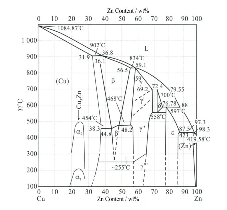
Table 2-7 Common Brass Grades and Chemical Composition
| Σειριακός αριθμός | Grade number | Chemical composition/% | |||||
|---|---|---|---|---|---|---|---|
| Cu | Fe | Pd | Ni | Zn | Συνολικές ακαθαρσίες | ||
| 95.0 ~ 97. 5 | 0.10 | 0.03 | 0.5 | Margin | 0.2 | ||
| 2 | H90 | 88. 0 ~ 91.0 | 0.10 | 0.03 | 0.5 | Margin | 0.2 |
| 3 | H85 | 84. 0 ~ 86. 0 | 0.10 | 0.03 | 0.5 | Margin | 0.3 |
| 4 | H80 | 79. 0 ~ 81.0 | 0.10 | 0.03 | 0.5 | Margin | 0.3 |
| 5 | H70 | 68. 5 ~ 71. 5 | 0.10 | 0.03 | 0.5 | Margin | 0.3 |
| 6 | H68 | 67.0 ~ 70.0 | 0.10 | 0.03 | 0.5 | Margin | 0.3 |
| 7 | H65 | 63. 5 ~ 68. 0 | 0.10 | 0.03 | 0.5 | Margin | 0.3 |
| 8 | H63 | 62.0 ~ 65.0 | 0.15 | 0.08 | 0.5 | Margin | 0.5 |
| 9 | H62 | 60. 5 ~ 63. 5 | 0.15 | 0.08 | 0.5 | Margin | 0.5 |
| 10 | H59 | 57. 0 ~ 60. 0 | 0.30 | 0.5 | 0.5 | Margin | 1.0 |
| (Liu Ping, 2007; Wang Biwen, 2007; Tian Rongzhang and Wang Shitang, 2002; National Nonferrous Metals Standardization Technical Committee, 2012) | |||||||
Table 2-8 Surface Colors of Ordinary Brass
| Grades | Copper content /wt% | Zinc content /wt% | Χρώμα |
|---|---|---|---|
| H59 | 59 ~ 63 | Margin | Light brown - golden color |
| H65 | 63 ~ 68. 5 | Margin | Pure yellow |
| H68,H70 | 68. 5 ~ 71. 5 | Margin | Green - Gold |
| H80 | 78. 5 ~ 81. 5 | Margin | Golden color with a hint of red |
| H85 | 84 ~ 86 | Margin | Brownish-yellow - golden |
| H90 | 89 ~ 91 | Margin | Antique bronze - gold color |
| H96 | 94 ~ 96 | Margin | Reddish-brown |

Due to zinc’s much lower electrode potential than copper, alloys are prone to electrochemical corrosion in neutral saline solutions. The lower potential zinc dissolves, while copper remains as a porous film on the surface, forming micro-batteries with the brass composition beneath the surface, causing the brass to act as an anode and accelerating corrosion. Therefore, brass jewelry generally require surface protection treatments, such as electroplating with a layer of precious metal or applying a protective coating.
(2) Special Brass
To improve the performance of simple brass, 1%~5% elements such as tin, lead, aluminum, silicon, iron, manganese, and nickel are added to the alloy, forming ternary, quaternary, or even quinary alloys, referred to as special brass or complex brass, and the name of the brass is prefixed with the added elements, such as tin brass, lead brass, aluminum brass, manganese brass, aluminum-manganese brass, etc. Tin can inhibit dezincification corrosion and enhance the corrosion resistance of brass. Lead has very low solubility in brass and is distributed as free particles in the matrix, which can cause chips to break and provide lubrication, thereby improving the machinability and wear resistance of the material. Aluminum plays a solid solution-strengthening role, forming a protective aluminum oxide film on the surface. Silicon brass has high corrosion resistance, mechanical and casting properties, and strong stress corrosion resistance. Nickel brass has high strength, toughness, and corrosion resistance and can withstand cold and hot plastic processing.
The complex structure of brass can be estimated based on the “zinc equivalent coefficient” of the elements added to the brass. Adding a small amount of other alloying elements to the copper-zinc alloy usually only shifts the phase region α/(α+β) in the state diagram Cu-Zn to the left or right. For example, adding 1% tin equivalent to the effect of 2% zinc on the structural properties means that the zinc equivalent of tin is 2. The zinc equivalents of various alloying elements are shown in Table 2-9.
Table 2-9 Zinc Equivalent of Various Alloying Elements
| Alloy elements | Silicon | Aluminum | Τενεκεδένιο | Lead | Σίδηρος | Μαγγάνιο | Νικέλιο |
|---|---|---|---|---|---|---|---|
| Zinc equivalent | + 10 | + 6 | + 2 | + 1 | + 0. 9 | + 0. 5 | —1. 3 |
Therefore, the structure of special brass usually corresponds to the structure of ordinary brass with an increased or decreased zinc content. The phase α and phase β in complex brass are multi-component complex solid solutions with a greater strengthening effect. In contrast, the phase α and phase β in ordinary brass are simple solid Cu-Zn solutions with a lower strengthening effect. Although the zinc equivalents are comparable, a multiple solid solution’s properties differ from those of a simple binary solid solution. Therefore, a small amount of multi-strengthening is a way to improve the performance of the alloy.
In special brass, a copper-based imitation gold alloy is known as “rare gold,” widely used in jewelry and crafts. It is well known that gold has a brilliant golden color, good chemical stability, does not change color when heated, and has excellent oxidation resistance, making it a long-standing choice for decorative art pieces. However, its high price makes low-cost alloys with similar properties widely used as substitutes. In recent years, researchers, both domestically and internationally, have been competing to develop copper-based imitation gold alloys to replace gold and significant progress has been made. The gold color of these materials can rival 16K~22K gold and have good corrosion resistance and workability.
In rare metal copper-based imitation gold alloys, zinc, aluminum, silicon, and rare earth elements are generally used as alloying elements, and the effects of each element on color and oxidation resistance are as follows.
① Zinc. Zn can change copper from red to yellow, the main element forming a golden-yellow luster. Zn can improve the discoloration resistance of alloys, and as the Zn content increases, the discoloration resistance improves.
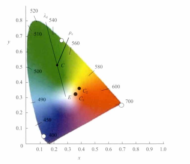
② Aluminum. Al is another major element that contributes to the color of alloys. The aluminum content significantly affects the color of the alloy; as the aluminum content increases, the main wavelength of light reflected by the alloy decreases, and the hue changes from red to yellow. Further increasing the aluminum content noticeably weakens the yellow hue of the alloy, leading to a greater color difference between the alloy and pure gold. The alloy structure becomes more uniform when aluminum is added to brass alloys. It promotes the formation of the phase β, which helps reduce dezincification corrosion in brass and improves the anti-discoloration performance of gold-like alloys in artificial sweat. The reason is that when the aluminum content is sufficiently high, a dense and firmly attached mixed oxide protective film of copper and aluminum forms on the surface of the alloy, and this film has self-healing capabilities when damaged. The anti-discoloration performance is poor when the aluminum content is too low to form a dense protective film.
③ Silicon. Si can improve the color and discoloration resistance of alloys. When 0.05%~2.50% Si added to the alloy, compared to the same alloy without Si, the discoloration resistance time in artificial sweat increases 50%~100%; at the same heating temperature, the discoloration resistance time increases 50%. Adding Si can also improve the fluidity and wear resistance of the alloy.
④ Rare earth. Adding rare earth elements to brass alloys can enhance the brightness of the alloy, improve its color, and provide good wear resistance, hardness, and a color similar to gold that does not easily fade. In the jewelry industry, it is commonly referred to as “rare gold material.” Jewelry made from rare gold material can have a color resembling 18K or 20K gold, is not easily oxidized or faded, making it suitable for daily wear, and is inexpensive, becoming a material for producing higher-end imitation gold jewelry.
Table 2-10 shows several common imitation gold-copper alloys, which can be classified into the copper-based alloy Cu-Al system and the Cu-Zn system.
Table 2-10 Chemical Composition of Several Imitation Gold Copper Alloys (Quality fraction unit: %)
| Grades number | Aluminum | Τενεκεδένιο | Νικέλιο | Silicon | Zinc | Μαγγάνιο | Rare Earths | Χαλκός | Παρατηρήσεις |
|---|---|---|---|---|---|---|---|---|---|
| Cu - 12. 5Zn - 1Sn | 1.0 | 12. 5 | The rest | Reddish-gold | |||||
| Cu - 22Zn - 2Sn - 1P | 2.0 | 22.0 | Phosphorus 1.0 | The rest | Light golden yellow | ||||
| Cu - 35Zn - 1. 5Sn | 1.5 | 30.0 ~ 40.0 | The rest | Χρυσοκίτρινο | |||||
| Cu - 6Al - 15Zn - 0. 5Si | 6 | 0. 5 | 15 | The rest | |||||
| Sub - gold | 5.6 | 0. 26 | 0.70 | 92.6 | Assayed Composition | ||||
| Sub - gold | 0.38 | 0.03 | 48.74 | 50.64 | Assayed Composition | ||||
| Rare - earth gold | 5 ~ 6 | 1 ~ 3 | 25 ~ 32 | 0. 8 ~ 1.5 | 0.1 | The rest | 18Kgold color | ||
| Rare - earth gold | 2 ~ 10 | 1 ~ 1.5 | 0. 05 ~ 2. 5 | 5 ~ 30 | 0. 05 ~ 0. 50 | The rest | 18Kgold color | ||
| (Wang Biwen et al., 1998) | |||||||||
1.2 The Properties of Brass
(1) Corrosion Resistance Performance
Brass has poor corrosion resistance in high temperature, high humidity, and salt mist atmospheres and can also experience “dezincification corrosion” in flowing hot seawater (zinc dissolves first, leaving a porous sponge-like pure copper on the surface of the workpiece). In humid atmospheres, especially those containing ammonia and SO2 , brass undergoes stress corrosion cracking. As newly polished brass ornaments, the surface will become dull or develop dark spots in certain areas even after being exposed to air for some time. Therefore, brass ornaments generally require surface coloring or electroplating treatment to improve their corrosion resistance.
(2) Casting Process Performance
The solidification range of brass is very small, so the fluidity of the liquid metal is good, the filling ability is excellent, and the tendency for shrinkage cavities is low. During melting, zinc generates a large vapor pressure, effectively removing gases from the copper liquid, making it difficult for pores to form in brass. The melting temperature is lower than tin bronze, and casting is relatively convenient, allowing for the easy casting of small jewelry pieces. It is also commonly used for the casting of copper crafts.
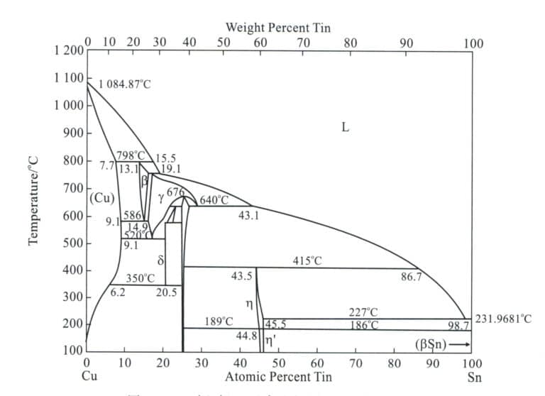
(3) Μηχανικές ιδιότητες
Due to the different zinc content in brass, the mechanical properties also vary. For α brass, as the zinc content increases, both σb and δ continuously rise. For (α+β) brass, the room temperature strength continuously improves when the zinc content increases to about 45%. If the zinc content is further increased, the strength sharply decreases due to the appearance of a more brittle phase γ (a solid solution based on compounds Cu5 Zn8 ) in the alloy structure. The room temperature plasticity of zinc content. On the other hand, (α+β) brass consistently decreases with the increase of the content of Zinc. Therefore, copper-zinc alloys with a zinc content exceeding 45% has no practical value.
(4) Machinability
Single-phase α brass (from H96 to H65) has good plasticity and can withstand cold and hot processing. However, single-phase α brass is prone to medium-temperature brittleness during hot processing such as forging, with the specific temperature range varying depending on the Zn content, generally between 200~700℃. Therefore, the temperature during hot processing should be above 700℃. The main reason for the medium-temperature brittleness zone in single-phase α brass is the presence of two ordered compounds Cu3 Zn and Cu9 Zn within the ordered phase α region of the alloy Cu-Zn system , which undergo ordered transformation during medium to low-temperature heating, making the alloy brittle; additionally, trace amounts of lead and bismuth harmful impurities form low-melting-point eutectic films distributed at the grain boundaries with copper, causing intergranular cracking during hot processing. Practice shows that adding trace amounts of cerium can effectively eliminate medium-temperature brittleness.
Two-phase brass (from H63 to H59) has, in addition to the ductile phase α in its alloy structure, a solid solution β based on the electronic compound CuZn. The phase has high ductility at high temperatures, while the phase β’ (ordered solid solution) is hard and brittle at low temperatures. Therefore, (α+β)brass should be forged in a hot state. Β Brass with a zinc content greater than 46%~50% is hard and brittle due to its properties and cannot be processed by pressure.
For relatively delicate jewelry, brass is generally processed using cold working. Brass materials such as wire, sheet, and plate materials can be used to obtain the final product through cold processing. Of course, during the processing, intermediate annealing is used to restore the plasticity of the brass and prevent cracking due to work hardening. Figure 2-7 shows a lobster clasp made of brass, and Figure 2-8 shows a bracelet made of brass. Brass plates can also be used for engraving, employing various manual techniques such as pushing, drilling, picking, twisting, and pulling to carve images on the surface of the copper plate. The engraved images are then electroplated with a 24K gold protective layer, resulting in the “gold sculpture painting.”
(5) Welding Performance
The welding performance of brass is good. For larger crafts, gas welding is usually used; for delicate jewelry, torch welding is generally employed.
(6) Polishing Performance
The cutting performance of brass is good, and it can withstand operations such as correction, polishing, and finishing. The jewelry can be polished to a very bright finish using conventional jewelry finishing methods.
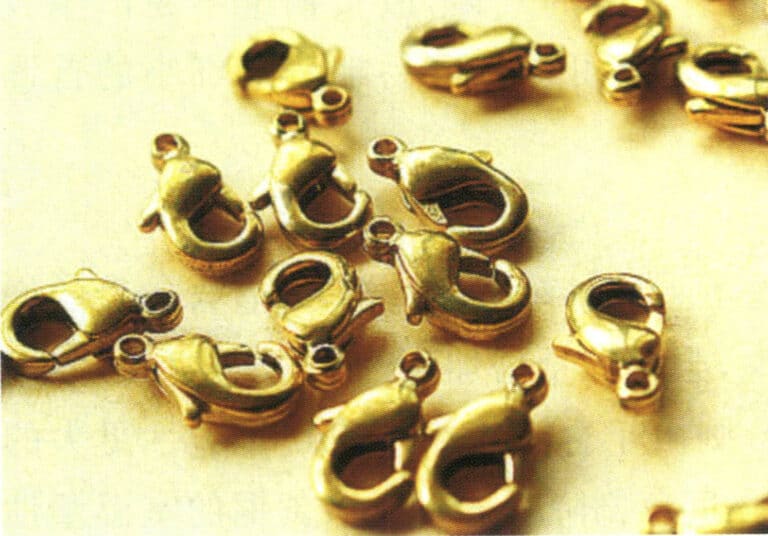
Figure 2-7 Brass processed lobster clasp
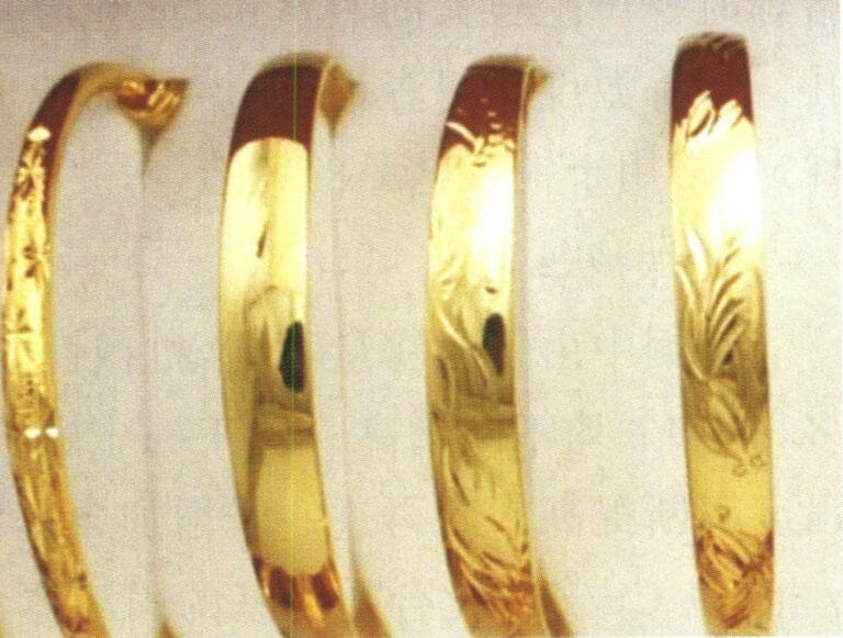
Figure 2-8 Brass bracelet
2. Cupronickel
2.1 Types of Cupronickel
Cupronickel can be divided into three categories: ordinary cupronickel, complex cupronickel, and industrial cupronickel.
(1) Ordinary Cupronickel
The copper-nickel binary alloy is called ordinary cupronickel, usually represented by the letter B, with the following number indicating the copper content, such as B30, indicating a copper-nickel alloy containing Ni 30%. Models include B0.6, B19, B25, B30, etc.
(2) Complex Cupronickel
A complex brass alloy containing elements such as manganese, iron, zinc, and aluminum is referred to as complex brass, represented by the letter B, and the alloy elements, such as BMn3-12, indicate a copper-nickel-manganese alloy containing Ni3% and Mn12%. There are four models of complex brass.
- Ferro-cupronickel. The models include BFe5-1.5(Fe)-0.5(Mn), BFe10-1(Fe)-1(Mn), BFe30-1(Fe)-1(Mn). The amount of iron added to ferro-cupronickel does not exceed 2% to prevent corrosion cracking, and its characteristics include high strength and significantly improved corrosion resistance, especially against flowing seawater corrosion.
- Manganese-cupronickel. Models include BMn3-12, BMn40-1.5, BMn43-0.5. Manganese-cupronickel has a low-temperature coefficient of resistance, can be used over a wide temperature range, has good corrosion resistance, and has good machinability.
- Zinc-cupronickel. Models include BZn18-18, BZn18-26, BZn18-18, BZn15-12 (Zn) – 1.8(Pb), BZn15-24(Zn)-1.5(Pb). Zinc-cupronickel has excellent comprehensive mechanical properties, outstanding corrosion resistance, good cold and hot processing formability, is easy to cut, and can be made into wire, rods, and plates materials, used for manufacturing precision parts in fields such as instruments, meters, medical devices, daily necessities, and communications.
- Aluminum-cupronickel. Models include BAl13-3 and BAl16-1.5. Lead bronze is an alloy formed by adding aluminum to a copper-nickel alloy. The properties of the alloy are related to the ratio of nickel and aluminum content in the alloy, with the best properties occurring when Ni:Al=10:1. Commonly used aluminum-cupronickel are Cu6Ni1.5Al, Cu13Ni3Al, mainly used in shipbuilding, electric power, chemical industry, and high-strength corrosion-resistant components in these industrial sectors.
(3) Industrial Cupronickel
Industrial cupronickel is divided into structural cupronickel and precision resistance alloy cupronickel (electrical cupronickel).
- Structural cupronickel. The characteristics of structural brass are good mechanical properties and corrosion resistance, with an attractive appearance. Among structural brass, the most commonly used are B30, B10, and zinc brass. In addition, complex brass such as aluminum brass, iron brass, and niobium brass also belong to structural brass. B30 has the strongest corrosion resistance among brasses but is relatively expensive. Zinc brass has been produced and used in China since the 15th century. It is known as “Chinese silver,” the so-called nickel silver or German silver belongs to this type of zinc brass. Zinc can be dissolved in large quantities in copper-nickel, producing solid solution-strengthening effects and corrosion resistance. Zinc cupronickel can be machined into precision parts after adding lead. Thus, it is widely used in instruments and medical devices. This alloy has high strength and corrosion resistance, good elasticity, an attractive appearance, and is inexpensive. The aluminum in aluminum cupronickel can significantly improve the strength and corrosion resistance of the alloy, and its precipitates can also produce precipitation-hardening effects. The performance of aluminum cupronickel is close to that of B30 and is inexpensive, making it a substitute for B30.
- Cupronickel for precision resistance alloys (electrical cupronickel). Cupronickel for precision resistance alloys (electrical cupronickel) has good thermoelectric performance. BMn 3-12 manganese copper, BMn 40-1.5 constantan, BMn 43-0.5 kovar, and new constantan with manganese instead of nickel (also known as nickel-free manganese cupronickel, containing 10.8%~12.5% manganese, 2.5%~4.5% aluminum, and 1.0%~1.6% iron ) are manganese cupronickel with different manganese content. Manganese cupronickel has high resistivity and low-temperature coefficient of resistivity, making it suitable for the production of standard resistance components and precision resistance components, and is used in the manufacture of precision electrical instruments, rheostats, meters, precision resistors, strain gauges, and other materials.
2.2 A Brief History of Cupronickel
The invention of cupronickel is an outstanding achievement in ancient China’s metallurgy technology. In ancient China, cupronickel was referred to as “Gan.” The “Old Book of Tang • Treatise on Clothing” states: “Only the oxen pulling the carriages of first-rank officials can be adorned with cupronickel.” This means that during the Tang Dynasty, it was stipulated that only the oxen of first-rank court officials could be decorated with cupronickel, indicating that cupronickel was quite valuable during that time. The people of Yunnan invented and produced cupronickel, making them among the earliest in China and the world, which is recognized by the academic community domestically and internationally. The cupronickel produced in ancient Yunnan was also the most famous, known as “Yun Cupronickel.”
The cupronickel artifacts manufactured in ancient China were sold throughout the country and exported abroad. According to research, as early as the Qin and Han dynasties, cupronickel coins were cast in the Daxia Kingdom, located west of Xinjiang, containing nickel up to 20%. Based on their shape, composition, and the historical conditions of the time, it is very likely that they were transported from China. During the Tang and Song dynasties, Chinese nickel cupronickel was already being exported to the Arab region, where the Persians referred to cupronickel as “Chinese stone.” After the 16th century, Chinese cupronickel was sold worldwide and received widespread acclaim. It was exported through Guangzhou and sold in Europe by the British East India Company. The English term “Paktong” or “Petong” is a transliteration of the Cantonese “cupronickel,” meaning cupronickel from China, specifically referring to the copper-nickel alloy produced in Yunnan.
In the 17th to 18th centuries, nickel cupronickel was widely introduced to Europe and was regarded as a precious item. It was called “Chinese silver” or “Chinese cupronickel,” and it significantly impacted the modern chemical industry in the West. After the 16th century, some European chemists and metallurgists began to study and imitate Chinese cupronickel.
In 1823, the German Heineger brothers successfully replicated Yunnan cupronickel. Soon after, the West began large-scale industrial production and renamed this alloy “German silver” or “nickel silver,” while the genuine Yunnan cupronickel became obscure. After Western countries successfully replicated Yunnan cupronickel, the export quantity of Chinese cupronickel significantly decreased. By the late 19th century, German silver had replaced Chinese cupronickel in the international market, leading to the decline of China’s cupronickel mining and metallurgy.
2.3 The Application of Cupronickel in Jewelry
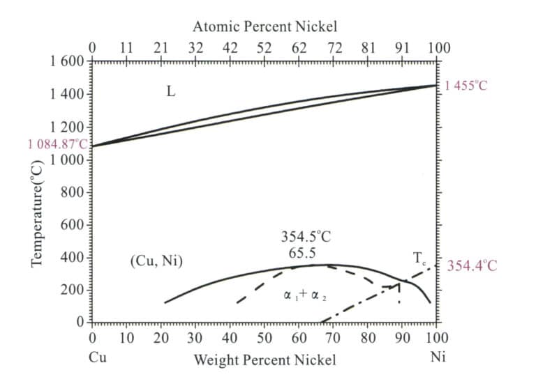
When nickel is melted into copper, and the content exceeds 16%, the resulting alloy becomes as white as silver. The higher the nickel content, the whiter the color. Combining pure copper and nickel can also significantly improve strength, corrosion resistance, and hardness. Therefore, while copper’s mechanical and physical properties are relatively good, it has an attractive appearance, is corrosion-resistant, and has excellent deep-drawing performance, making it a great material for jewelry. It is often widely used to make imitation silver and imitation platinum jewelry, with hardness and luster very close to silver jewelry, but at a much lower price.
In jewelry made of cupronickel materials, the most commonly used is zinc cupronickel, with its typical grades and composition shown in Table 2-11 and the properties of zinc cupronickel shown in Table 2-12.
Table 2-11 Chemical Composition of Domestic Zinc Cupronickel
| Grades | Chemical composition /% | ||||||||||||
|---|---|---|---|---|---|---|---|---|---|---|---|---|---|
| Ni+Co | Fe | Mn | Zn | Pb | Si | P | S | C | Mg | Sn | Cu | Συνολικές ακαθαρσίες | |
| BZn 18-18 | 16. 5 ~ 19. 5 | 0.25 | 0.50 | Margin | 0.05 | - | - | - | - | - | - | 63. 5 ~ 66. 5 | - |
| BZn 18-26 | 16. 5 ~ 19. 5 | 0.25 | 0.50 | Margin | 0.05 | - | - | - | - | - | - | 53. 5 ~ 56. 5 | - |
| BZn 15-20 | 13.5 ~ 16. 5 | 0.5 | 0.3 | Margin | 0.02 | 0.15 | 0.005 | 0.01 | 0.03 | 0.05 | 0.002 | 62.0 ~ 65.0 | 0.9 |
| BZnl5-21-1.8 | 14. 0 ~ 16.0 | 0.3 | 0.5 | Margin | 1. 5 ~ 2.0 | 0.15 | - | - | - | - | - | 60. 0 ~ 63.0 | 0. 9 |
| BZnl5 -24-1.5 | 12. 5 ~ 15.5 | 0.25 | 0. 05 ~ 0. 5 | Margin | 1. 4 ~ 1. 7 | - | 0.02 | 0. 005 | - | - | - | 58. 0 ~ 60. 0 | 0.75 |
| (Liu Ping, 2007; Wang Biwen, 2007; Tian Rongzhang and Wang Shitang, 2002; National Nonferrous Metals Standardization Technical Committee, 2012) | |||||||||||||
Table 2-12 Physical and Mechanical Properties of Zinc Cupronickel
| Επιδόσεις | Κράμα | |
|---|---|---|
| BZnl5-20 | BZnl7-18-1.8 | |
| Liquid phase point /℃ | 1 081.5 | 1 121.5 |
| Solid phase point/℃ | - | 966 |
| Density ρ/ g·cm-3 | 8. 70 | 8.82 |
| Heat capacity c/J • (g·°C)-1 | 0.40 | - |
| 20-100℃ Coefficient of linear expansion α/℃-1 | 16. 6X10⁻⁶ | - |
| Thermal conductivity λ/W·(m·℃)-1 | 25 ~ 360 | - |
| Resistivity ρ/μΩ·m | 0.26 | - |
| Resistance Temperature Coefficient αR/℃-1 | 2X10⁻⁴ | - |
| Modulus of elasticity E/GPa | 126 ~ 140 | 127 |
| Tensile strength σb/MPa | 380 ~ 450 soft state,800 hard state | 400 soft state,650 hard state |
| Elongation δ/% | 35 ~ 45 soft state,2 ~ 4 hard state | 40 soft state,2.0 hard state |
| Yield strength σ0.2 /MPa | 140 | - |
| Σκληρότητα Brinell HB | 70 soft state,160 ~ 175 hard state | - |
| Cutting performance(compare to HPb63 - 3)/% | - | 50 |
| (Liu Ping, 2007; Wang Biwen, 2007; Tian Rongzhang and Wang Shitang, 2002; National Nonferrous Metals Standardization Technical Committee, 2012) | ||
2.4 The Development of Cupronickel Materials
Nickel cupronickel has many excellent properties as a material for jewelry, but it also has some drawbacks. Since the main additive element, nickel is a scarce material, the price of cupronickel is relatively high. Additionally, due to the widespread concern about the harmful effects of nickel in various countries, products made for contact with human skin, such as zippers, eyeglass frames, coins, cutlery, and jewelry, may cause skin allergic reactions. Therefore, nickel-cupronickel materials have faced challenges in recent years, making the development of new nickel-free cupronickel alloys particularly important.
So far, most of the research on nickel-free cupronickel has been focuses on the Cu-Mn-Zn alloy, and the main roles of each alloying element are as follows.
(1) Manganese
Manganese is the main additive element in nickel-free cupronickel alloys. It can reduce the yellow and red components in the color of copper’s surface, acting as a bleaching or fading agent, changing the color of the alloy from colored to colorless. Manganese can improve the mechanical properties of the alloy by strengthening the solid solution. Partially replacing zinc with manganese can improve aging crack conditions. Manganese can suppress the evaporation of zinc during smelting and reduce material costs. However, if the manganese content exceeds 15%, the alloy will exhibit a α+β multiphase structure, leading to poorer processing performance. Manganese is detrimental to the casting performance of the alloy; during smelting, manganese easily oxidizes to form high-melting-point manganese oxide inclusions, which have a high density and are difficult to float out of the molten metal, making it easy for castings to have inclusion defects. Additionally, manganese increases the shrinkage rate of the alloy, reducing its fluidity, and high manganese content can worsen the processing performance of the alloy. Therefore, from the perspective of process performance, the manganese content should not be too high.
(2) Zinc
Zinc can improve the strength and hardness of alloys through solid solution strengthening, lower the melting point of alloys, enhance forming performance, and reduce the cost of alloys. When the zinc content is too low, the strengthening effect is poor; increasing the zinc content can improve the strengthening effect. However, zinc significantly reduces the corrosion resistance of copper, especially when the zinc exceeds 22%, causing the alloy to transform into a α+βmultiphase structure, which deteriorates processing performance and is prone to aging crack issues induced by residual stress. When the zinc content is less than about 30%, increasing the zinc content reduces the red component in the color of the Cu-Mn-Zn alloy while increasing the yellow component and brightness value. Zinc also has an important impact on the color stability of alloys; as the zinc content increases, the alloy’s resistance to discoloration in artificial sweat decreases.
(3) Aluminum
Aluminum is one of the most important coloring elements in imitation gold alloys. As the aluminum content increases, the Cu-Zn-Al ternary alloy’s brightness value and yellow component increase while the red component decreases. The zinc equivalent coefficient of aluminum is very high; every 1% aluminum is equivalent to 6% of zinc, so the α-phase region is significantly reduced after adding aluminum. Aluminum can form a dense oxide film on the surface of the alloy, which can improve the aging cracks and dezincification corrosion issues of the alloy, and it also produces solid solution strengthening, which is beneficial for improving the mechanical properties of the alloy. When the aluminum content is too low, the strengthening effect is insufficient and not enough to resist aging cracks. However, if its content exceeds 4%, it becomes difficult to purify the molten metal during alloy smelting, and a complex α+β phase structure appears, deteriorating cold working performance.
(4) Tin
The zinc equivalent coefficient of tin is 2, so adding a small amount of tin has little effect on the structure, and the alloy remains single-phase. Tin has a certain solid solution-strengthening effect. Still, if its content exceeds a certain level, it is prone to form low melting point phases at the grain boundaries, which is detrimental to mechanical properties. A small amount of tin also has little effect on the color of the Cu-Mn-Zn alloy; its main role is to form a SO2 protective film on the surface of the alloy, which can greatly improve the alloy’s resistance to discoloration. Tin can increase the fluidity of the alloy and improve casting performance, but it increases the cost of the alloy.
(5) Rare Earth
Trace amounts of the rare earth element cerium can refine grain size, improve the tensile strength and elongation of the alloy, and enhance the cold working performance of the alloy.
By comprehensively utilizing these elements, researchers at home and abroad have developed a series of multi-element nickel-free white Cu-Mn-Zn alloys, such as Cu- 12Mn -8Zn – 1Al – 0.04%Ce, Cu – 15Mn – 15Zn – 1Al, Cu – 20Mn – 20Zn – 0.3Al – 0.2Sn – 0.05Mg, etc.
3. Bronze
The other copper alloys are called bronze, except brass and cupronickel. Bronze generally refers to the alloy of red copper with tin, lead, and other chemical elements, named for its bluish-gray color. Bronze is divided into tin bronze and non-tin bronze, with tin bronze being the oldest artistic casting alloy in history. Non-tin bronze is a new type of bronze developed in modern times, which uses elements like silicon and aluminum to replace the more expensive tin while further improving some properties of tin bronze. The greatest advantage of bronze is its excellent wear resistance, and it also has high corrosion resistance in steam, seawater, and alkaline solutions, which is an important reason why ancient bronze artworks have been perfectly preserved to this day. Additionally, bronze has a lower melting point, better casting performance, and good mechanical properties.
Bronze used for artistic castings typically includes tin bronze, silicon bronze, aluminum bronze, etc.
3.1 Tin bronze
Tin bronze is an ancient casting art copper alloy with a history of over 5000 years. Most of the treasures of the ancient casting art of the Chinese nation were cast in tin bronze, such as the Simuwu Ding from the Shang Dynasty, the ritual vessels from the Spring and Autumn and Warring States periods, and the bianzhong (bronze bells), among others.
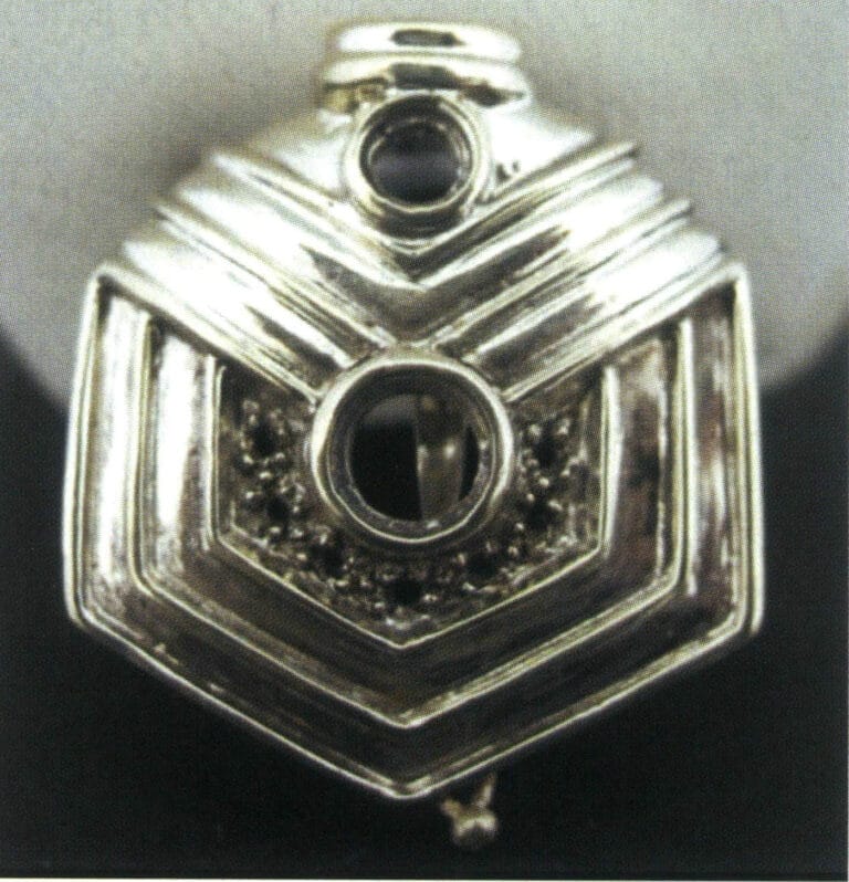
(1) The Structure and Performance Characteristics of Tin Bronze
Tin bronze is based on a copper-tin alloy; the diagram (Figure2-11) is the Cu-Sn binary phase diagram and exits α, β, γ, δ phases, among which α phase is a substitutional solid solution of tin dissolved in pure copper, with a face-centered cubic lattice, thus retaining the good plasticity of pure copper. Β phase is a solid solution based on the electronic compound Cu5 Sn, with a body-centered cubic lattice, existing at high temperatures and decomposed during the cooling process. Γ phase is a solid solution based on CuSn, with properties similar to β phase. δ phase is a solid solution based on the electronic compound Cu31 Sn8 , with a complex cubic lattice, existing at room temperature, hard and brittle.
(2) The Role of Alloying Elements in Tin Bronze
① Zinc. Adding zinc to tin bronze can reduce the crystallization temperature range of tin bronze, improve the fluidity of the alloy, and decrease the tendency to produce shrinkage cavities. Additionally, zinc has a relatively high vapor pressure during melting, and the zinc vapor formed can prevent the oxidation of copper and tin elements, purifying the alloy and reducing the tendency to form pores. The effect of zinc on the structure and properties of tin bronze is similar to that of tin, with the addition of 2% zinc being equivalent to the role of 1% tin. However, the price of zinc is much lower than that of tin, so zinc can be used to replace tin to reduce costs. If the zinc content exceeds 5%, it can make the patterns unclear, increase susceptibility to corrosion, and make it difficult to generate an elegant green outer layer.
② Lead. Lead has a very low hardness and is distributed in a particulate form in tin bronze, improving the wear resistance of the alloy and facilitating the processing of bronze. At the same time, lead’s low melting point enhances the fluidity of tin bronze. During solidification, lead accumulates in the gaps between dendrites, reducing shrinkage and preventing leakage, with the best anti-leakage effect generally achieved at a lead content of around 5%. Lead has a relatively high specific gravity in bronze, and excessive lead can cause gravitational segregation, so it is important to stir the lead-containing tin bronze before pouring and to use water cooling or metal molds to accelerate cooling and prevent segregation.
③ Nickel. Nickel is infinitely soluble in the solid solution of bronze, promoting the development of α dendrites; thus, adding a small amount of nickel can reduce the segregation of tin and lead. Adding 1%~2% nickel can refine the grains, improve mechanical properties, corrosion resistance, and thermal stability, and enhance the casting performance of bronze. A larger amount of nickel will make the bronze appear whiter.
④ Iron. The main function of iron is similar to that of nickel; it can refine grains, increase strength, and improve coloring performance. However, the content must be controlled below 5%; otherwise, it will make bronze brittle and reduce corrosion resistance.
⑤ Aluminum. In tin bronze, aluminum is a harmful impurity that makes coloring difficult. As long as 0.5% aluminum is present, the surface changes from dark red to golden yellow and then to silver white. However, aluminum can improve strength, corrosion resistance, and casting performance in lead-free bronze.
⑥ Phosphorus. 0.03%~0.06% phosphorus must be added to tin bronze to deoxidize it and improve casting performance; excessive amounts can easily produce a brittle phase Cu3 P and reduce coloring effects.
⑦ Silicon. Adding silicon to bronze will deteriorate its mechanical and casting properties but can increase corrosion resistance. Silicon gives the surface a dark red to brown color, sometimes appearing purple, due to a very dense SiO2 film covering the surface, making coloring difficult.
Tin bronze has a beautiful appearance and excellent processing performance. It has been widely used in casting crafts from ancient times. Table 2-13 lists some commonly used tin bronze materials for artistic castings.
Table 2-13 Tin Bronze for Artistic Castings
| Name, grades | Main chemical components /% | Impurity /%≯ | Παρατηρήσεις | ||||||||
|---|---|---|---|---|---|---|---|---|---|---|---|
| Sn | Zn | Pb | A1 | Cu | Sb | Fe | Al | Σύνολο | |||
| ZCuSn2Zn3 | 1.8 ~ 2.2 | 2.5 ~ 3.5 | Margin | China Standard | |||||||
| ZCuSn3A12 | 2.5 ~ 3.5 | 1.5 ~ 3.5 | Margin | China Standard | |||||||
| ZCuSnl2Mnl | 10 ~ 15 | 0. 15 ~ 0. 25 | 0. 2 ~ 0. 3 | Mn 1.0 ~ 1. 25 | Margin | China Standard | |||||
| ZCuSn5Zn5Pb5 | 4.0 ~ 6.0 | 4.0 ~ 6.0 | 4.0 ~ 6.0 | Margin | China Standard | ||||||
| ZCuSn10Zn2 | 9.0 ~ 11.0 | 1.0 ~ 2.0 | Margin | China Standard | |||||||
| BC1 | 2.0 ~ 4.0 | 8.0 ~ 12.0 | 3.0 ~ 7.0 | 79. 0 ~ 83. 0 | 2.0 | Japanese Standard | |||||
| BC6 | 4.0 ~ 6.0 | 4.0 ~ 6.0 | 4.0 ~ 6.0 | 82. 0 ~ 87.0 | 2.0 | Japanese Standard | |||||
| BC7 | 5.0 ~ 7.0 | 3.0 ~ 5.0 | 1.0 ~ 3.0 | 86. 0 ~ 90. 0 | 1.5 | Japanese Standard | |||||
| G - CuSn5ZnPb | 4.0 ~ 6.0 | 4.0 ~ 6.0 | 4.0 ~ 6.0 | 84. 0 ~ 86. 0 | 0.3 | 0.3 | P0. 05 | S0. 10 | Germany Standard | ||
| C90300 | 7.5 ~ 9.0 | 3.0 ~ 7.0 | 86.0 ~ 89. 0 | 0.2 | 0.15 | 0. 005 | Si0. 005 | 1.76 | American Standard | ||
| (Tian Rongzhang and Wang Zhutang, 2002) | |||||||||||
Tin bronze is used for casting artworks and is capable of withstanding high temperatures, high humidity, and exposure to urban waste gases (mainly CO2, SO2, NO gases) and even acid rain. In the normal atmosphere, the corrosion rate of tin bronze is 0.001mm/a; in the coastal atmosphere, it is 0.002mm/a; in the industrial atmosphere, it is 0.002~0.006mm/a.
Large outdoor cast art pieces may crack due to stress caused by sunlight, temperature differences, and welding in a corrosive atmosphere. Tin bronze has a low tendency for stress cracking, which can effectively reduce this risk. For example, the Tian Tan Buddha in Hong Kong is made of 8% Sn and 4%, with the rest being copper, cast, and welded together, and was completed in 1989. It has stood safely on Lantau Island’s Muk Yu Peak in Hong Kong ever since.
3.2 The Application of Bronze in Craft Ornaments
Due to the beautiful appearance and excellent processing performance of bronze, it has been widely used as a material for craft jewelry from ancient times to the present.
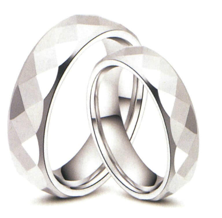
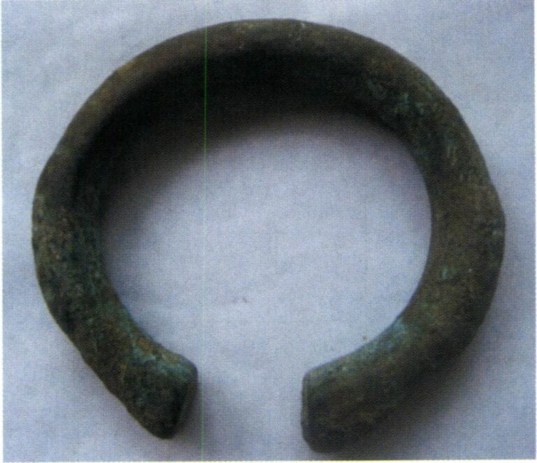
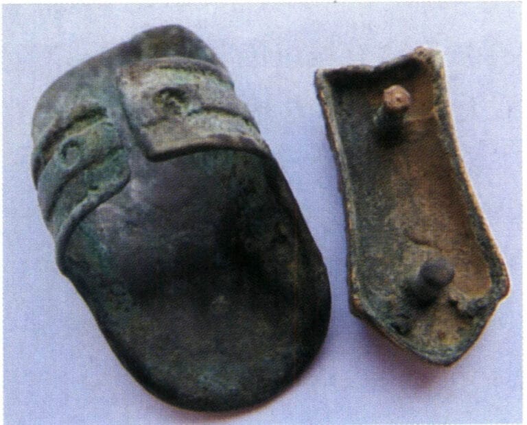
In ancient times, in addition to being widely used as utensils, it was also used for delicate and intricate ornaments, such as bronze bracelets from the Han Dynasty and bronze rings from the Liao Dynasty. Today, the application of bronze in crafts and jewelry has great development potential, especially with the improvement of economic levels, the rapid development of bronze casting, high market demand, a wide variety of products, and various methods of replication, imitation, and creation. It is widely used as urban sculptures, temple ritual vessels, Buddha statues, decorative paintings, and collectibles. In terms of jewelry, bronze is also used to make various ornaments and accessories. For example, the famous Greek fashion brand Folli Follie specializes in designing, manufacturing, and distributing jewelry, watches, and accessories. The company has launched the Precious Bronze series, combining bronze and silver. The necklaces, bracelets, and earrings are irregularly round, evoking a nostalgic feeling reminiscent of a land bathed in golden sunlight. The mix of different materials and the freshness of silver create beautiful curves. These luxurious treasures carry the brilliant characteristics of Folli Follie, exuding the elegance and beauty of true fashionistas.

Hong Kong Tian Tan Buddha (Bronze)
Liao Dynasty bronze ring
Bronze bracelet from the Han Dynasty
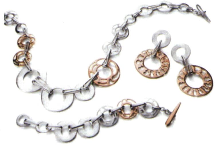
Folli Follie company's precious bronze jewelry (bronze + silver)
Copywrite @ Sobling.Jewelry - Κατασκευαστής προσαρμοσμένων κοσμημάτων, εργοστάσιο κοσμημάτων OEM και ODM
Section IV The Craftsmanship of Copper jewelry
1. The Lost Wax Casting Process for Copper jewelry
Gypsum mold casting has become the main method for jewelry making, and the typical process flow for copper jewelry lost-wax casting is as follows:
Original model making→ Rubber molds making (compression molds, vulcanization, opening molds)→ Making wax molds (wax injection, wax finishing)→ Planting wax model trees→ Mold casting making (mixing casting powder slurry, vacuuming, pouring slurry, vacuuming, dewaxing, burnout)→ Smelting and pouring (alloy pretreatment, smelting, pouring)→ Casting cleaning (removing casting powder, acid immersion, pre-polishing)→ Post-processing (mold finishing, setting, polishing, electroplating).
1.1 Original Model
Determine the appropriate original version production method based on the complexity of the workpiece, specifications, and the customer’s quality requirements. The jewelry original model production methods are divided into three categories: hand-carved wax models, computer-generated models, and hand-crafted silver models. Taking hand-carved wax models as an example, the main process includes the following aspects: looking at the order and cutting the material→ rough finishing→ fine finishing→ removing the bottom weight→ opening the stone setting position→ repairing.
(1) Looking at the Order and Cutting the Material
Understand customer requirements based on the order, such as size, stone size, wax weight limit, etc. Select a suitable wax material for the workpiece, then mark lines on the wax material, and use a saw blade or bow saw to cut along the marked lines.
(2) Rough Finishing
Draw the main lines on the material, including the inner and outer contours. Use a coarse strip to sew off the excess parts. Install the finishing bur on the electric hanging flexible shaft grinder for preliminary processing, first creating a rough outline. Then, switch to the steel bur and shallow the deep marks left by the coarse strip and finishing bur tool (Figure 2-13). Finally, use a file to remove the marks the steel bur leaves, making the surface smooth.
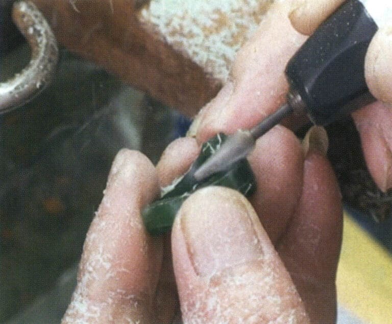
Figure 2-13 Rough finishing processing
(3) Fine Finishing
Fine finishing is based on rough finishing and further processing to make the entire wax sample more refined and aesthetically pleasing. First, a compass is used to take the dimensions of each part on the wax sample template and draw some auxiliary lines. Based on these auxiliary lines, remove the excess wax with a finishing bur, then use a steel bur to smooth out the rough marks left from the previous process. Use large and small spatulas to level off any corners or protruding parts on the wax sample, and refine it with a scalpel. Finally, large and small files smooth the overall wax sample.
(4) Removing Bottom Weight
The purpose of removing bottom weight is to reduce the weight of the workpiece. Install the ball bur and wheel bur on the electric hanging flexible shaft grinder, and use the ball bur to remove excess wax material at the bottom of the pattern head or the inner circle of the ring shank (Figure 2-14). Generally, the reserved bottom thickness for pave setting is 1.1 mm; for light gold and flush setting, it is 0.7 mm; for bezel setting and channel setting, it is 1.6 mm. Then, use a dental bur, drill bur, surgical knife, etc., to trim the wax sample’s bottom frame. During the bottom weight removing, it is important to frequently measure the dimensions at the light gold position, pave setting position, channel setting position, etc., using internal calipers to prevent deviations.
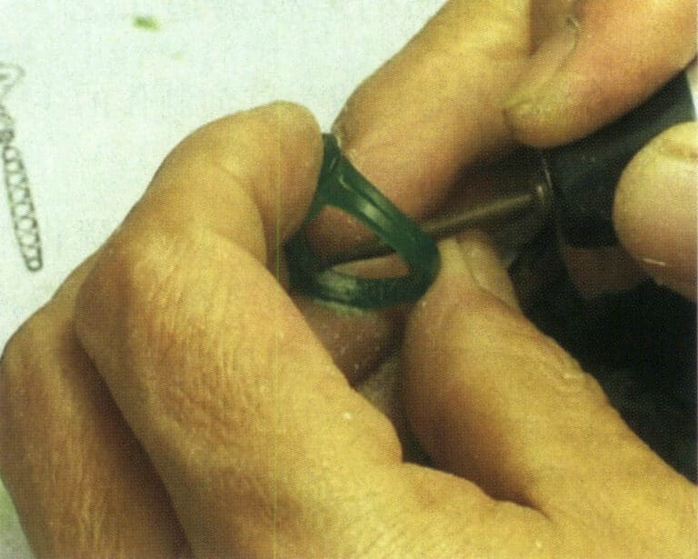
Figure 2-14 Removing the bottom weight
(5) Make the Stone Setting Position
According to the size of the stone and the setting method, open the stone position, use appropriate diamond drills for channel setting and bezel setting, drill holes at the designated stone position, and then use steel burs, small files, scalpels, etc. for adjustments; steel burs can also be used to directly open the stone position.
(6) Repair
Repair involves adjusting certain details to ensure that the repaired workpiece better meets the order requirements. During the repair, attention should be paid to adjusting and coordinating the relationship between wax weight and size according to the order’s requirements for product weight and dimensions.
(7) Polishing
Wipe the surface of the wax plate with nylon cloth to make it smooth and fine.
(8) Replicating Silver Model
After the hand-carved wax model is completed, it must be cast into a silver model to replicate the rubber mold. The surface of the cast silver model is then refined (Figure 2-15) to ensure a good surface finish, avoiding any defects on the silver model from being replicated onto the casting. The silver model’s shape, dimensions, and weight are checked to meet the order requirements. Additionally, some processes that the hand-carved wax model cannot complete are supplemented, such as planting prongs, creating buckles and buttons, dangling earrings, etc.
(9) Welding Sprues
The sprue is designed to leave a channel for the flow of molten metal during the casting process. In jewelry casting, because there is no set risers on the workpiece to make up for the contraction, the sprue has become a channel for the liquid metal filling but also needs to bear the liquid metal solidification contraction within the makeup for the contraction of the task, the correct setting of the sprue is to ensure that the casting quality of the basic conditions of the casting of many of the defects of the casting of the molten mold directly or indirectly by the setting of the sprue caused by the irrationality of the defects, such as insufficient filling, loosening, porosity, and other common defects.
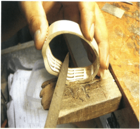
Figure 2-15 Finishing the silver model
1.2 Rubber Mold Making
(1) Πλήρωση και συμπίεση ακατέργαστου καουτσούκ
Use an oil-based pen to draw the parting line along the edge of the model shape as the parting position for cutting the rubber mold. The parting line position is determined based on the principle of facilitating mold removal. Prepare the rubber plate and rubber particles according to the dimensions of the silver model, place the silver model in the appropriate position on the rubber plate, and fill the gaps, recesses, and stone-setting positions on the master model using methods such as plugging, wrapping, patching, and filling, ensuring there are no gaps between the silicone rubber plate and the master plate (Figure 2-16). Then, the remaining rubber plate is applied; to ensure the longevity of the rubber mold, it is usually pressed with more than four layers of silicone film. After being pressed into the mold frame, the rubber mold’s thickness is slightly higher than the plane of the frame by about 2 mm. During the operation, the silicone rubber plate must be kept clean, and direct contact with the surface of the silicone rubber plate should be avoided; instead, the protective rubber plate on the surface should be torn off after the silicone film is adhered.

Figure 2-16 filling rubber
(2) Vulcanization
First, preheat the vulcanizer, then place the molding frame with the pre-pressed silicone sheet inside and tighten the handle to press the heating plate against the molding frame. Carefully check if the heating plate is pressed tightly (Figure 2-17). The commonly used rubber has a vulcanization temperature range from 143~173℃, and the optimal temperature depends on the type of rubber. Before heating, press for a few minutes, then gradually increase the pressure. Choose the vulcanization time based on the model’s thickness; for example, 30 minutes for 12 mm thick, 45 minutes for 18 mm, and 75 minutes for 36 mm. Once the vulcanization time is up, quickly remove the rubber mold, and after it cools naturally to room temperature, you can proceed with the mold opening operation.
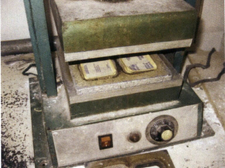
Figure 2-17 Sulfurization
(3) Opening the Rubber Mold
Opening the rubber mold involves cutting the pressed rubber mold to take out the original model (Figure 2-18) and dividing the rubber mold into several parts according to the complexity of the shape of the sample so that the wax mold can be smoothly removed after the wax injection. The opening of the rubber mold usually employs a four-foot positioning method.
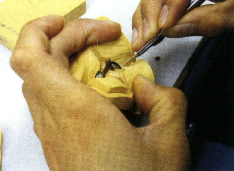
Figure 2-18 Opening mold
1.3 Wax Mold Making
Due to the fine nature of jewelry, when making wax molds, it is necessary to use the pressure of a wax injection machine to inject the wax liquid into the cavity of the rubber model. Many wax injection machines exist, including ordinary air-pressure wax injection machines, vacuum wax injection machines, and digital automatic wax injection machines. Place the wax material in the wax tank. The wax material must be kept clean, and the wax tank and nozzle’s temperature must be adjusted to the required temperature.
Before applying the wax, open the silicone mold and check its integrity and cleanliness. Spray release agent in the mold’s smaller, more complex areas (or sprinkle a small amount of talcum powder) to facilitate the removal of the wax mold.
Start the vacuum pump during wax injection and check if the wax temperature is between0~75℃. Adjust the injection time and air pressure according to the complexity of the wax parts in the mold, then evenly clamp the mold to perform the wax injection operation (Figure 2-19). The wax piece can be removed from the mold after cooling for about 1 minute. Care should be taken when removing the mold to avoid breaking or deforming the wax piece.
After removing the wax mold, carefully inspect it. If there are defects such as flash, clamping marks, unclear flower heads, or overlapping flower heads, they need to be trimmed with a surgical blade; for sand holes and broken claws, they can be repaired with a wax welder; small holes that are blocked can be penetrated with a welding needle; for deformation of the wax mold, it can be corrected in hot water at 40~50℃. Finally, cotton soaked in alcohol removes the wax shavings from the mold.
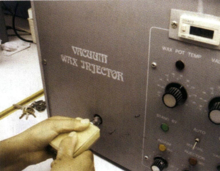
Figure 2-19 wax injection
1.4 Plating Wax Model Tree

Figure 2-20 Planting Wax Model Tree
1.5 Production of Gypsum Molds
(1) Investment – Mixing powder and Grouting
In the mold-making process, some typical machinery and equipment will be used, including simple powder mixers, vacuum extractors, automatic vacuum powder mixers, etc. The typical gypsum casting powder mixing and grouting process is shown in Figure 2-21.
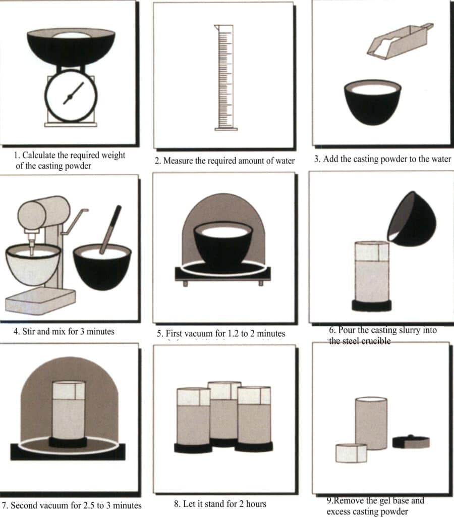
Figure 2-21 Schematic diagram of the gypsum casting powder mixing and grouting process
Due to the static electricity generated on the wax model tree, which easily attracts dust, it can be immersed in a surfactant or diluted detergent before grouting, washed with distilled water, and dried. During the powder mixing and grouting process, attention should be paid to appropriately controlling the setting time of the gypsum slurry. If it sets too quickly, the gas cannot be expelled in time; if it sets too slowly, the powder can easily settle in the slurry, resulting in a local change in the solid-liquid ratio, causing different roughness on the top and bottom of the jewelry.
After the casting mold is completed and the vacuum operation is performed, it should be allowed to stand for 1.5~2 hours to fully solidify and harden the gypsum mold. Then, remove the rubber base, the wrapping material around the steel flask, and the splattered slurry, and make marks on the side and surface of the casting mold.
(2) Wax Removal from the Mold
After the slurry solidifies, there are two different methods to remove the wax: steam dewaxing or drying dewaxing in a burnout furnace.
Steam dewaxing can remove wax more effectively and benefit the environment. Note that the boiling of water should not be too vigorous, and the time for steam dewaxing should be controlled; otherwise, splashed water may enter the mold and damage the surface of the mold. Additionally, in wax-setting casting, using steam dewaxing may dilute the boric acid protectant in the casting powder, leading to issues such as cloudy or discolored gemstones.
Burnout dewaxing is a method that directly uses a burnout urnace to heat the mold, allowing the wax material to melt and flow out of the mold. Due to the low boiling point of the wax material, when using this method, if the wax liquid boils violently, it can damage the surface of the mold, or if the wax liquid is not discharged smoothly, it can seep into the surface layer of the mold, both of which will deteriorate the surface quality of the casting. Therefore, it is important to control the heating temperature and speed during the dewaxing stage and to set up a corresponding insulation platform.
(3) Molding Burnout
The purpose of burnout is to eliminate the moisture from the gypsum mold and the residual wax, achieving the desired high-temperature strength and mold’s air permeability and meet the mold temperature requirements during pouring. The burnout system and equipment largely influence the final performance of the gypsum mold.
The gypsum burnout furnaces used in the jewelry industry generally adopt resistance furnaces, and some use oil-fired furnaces. Regardless of the type of furnace, the temperature distribution inside the furnace must be as uniform as possible. The resistance burnout furnace is commonly used, which generally adopts three-sided heating, and some use four-sided heating. They usually come with temperature control devices and can achieve segmented temperature control. Still, the temperature distribution inside the furnace is not uniform enough, and it is also difficult to adjust the atmosphere inside the furnace during burnout. In recent years, some advanced burnout technologies have continuously emerged, focusing on achieving uniform temperature distribution inside the furnace, eliminating wax residues, and automating control furnace. For example, a type of furnace uses a rotating bed method, with heating on all four sides, providing uniform and stable heat. The gypsum mold can be evenly heated, making it particularly suitable for the requirements of wax-set casting processes.
When roasting the mold, a suitable roasting system must be established, and a heat preservation platform should be set up during several sensitive stages. The mold is burn out at the highest temperature for 3~4 hours. After all residual carbon is burned off, the mold temperature needs to be lowered to a certain temperature to prevent defects such as shrinkage and porosity in the casting due to excessive mold temperature; however, since jewelry pieces are generally quite delicate and difficult to form, cold mold pouring is not used to ensure complete filling. Otherwise, the surface of the casting is prone to roughness and unclear contours. Generally, depending on the structure of the workpiece and the amount of casting, the mold temperature during pouring is between 520~650℃.
1.6 Melting and Pouring
(1) Alloy Pretreatment
In the casting production of jewelry, the effect of jewelry castings is closely related to the condition of the jewelry alloy. When pure metals and intermediate alloys are directly mixed and poured, it is easy to produce problems such as uneven composition, severe loss, and defects like holes. Therefore, it is generally necessary to pre-treat the jewelry alloy by melting and pouring various pure metals and alloy materials into beads or casting them into ingots and then proportioning them according to the required weight. The method of prefabricated beads is usually preferred, where the molten metal flows out from the crucible and instantly cools and splits into droplets when dripped into cooling water, solidifying solid metal particles (Figures 2-22 to 2-24). The round and appropriately sized alloy particles are beneficial for uniform composition during the melting process, temperature control, and reducing defects such as holes, sand holes, and hard spots, which are also closely related to the control of metal loss.
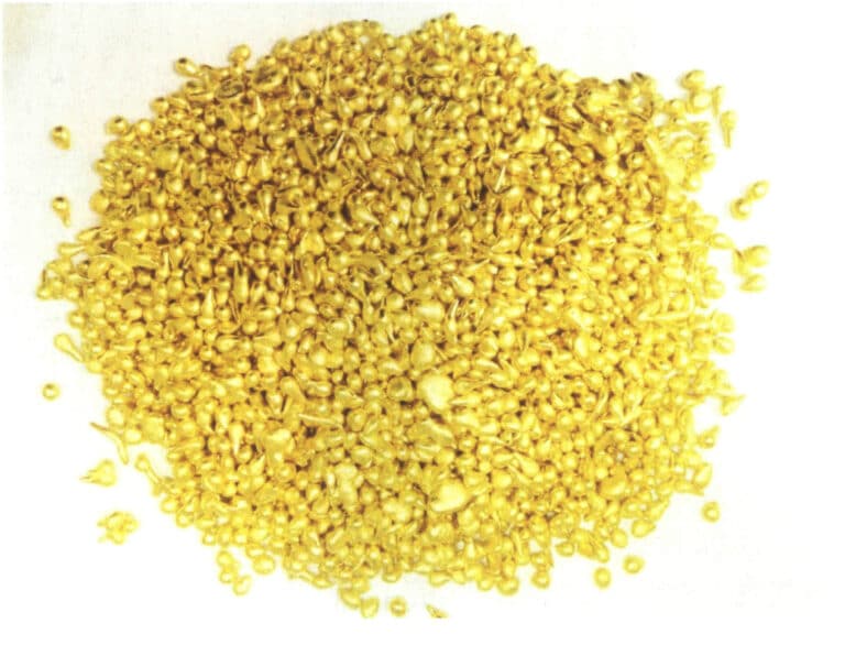
Figure 2-22 Brass particles
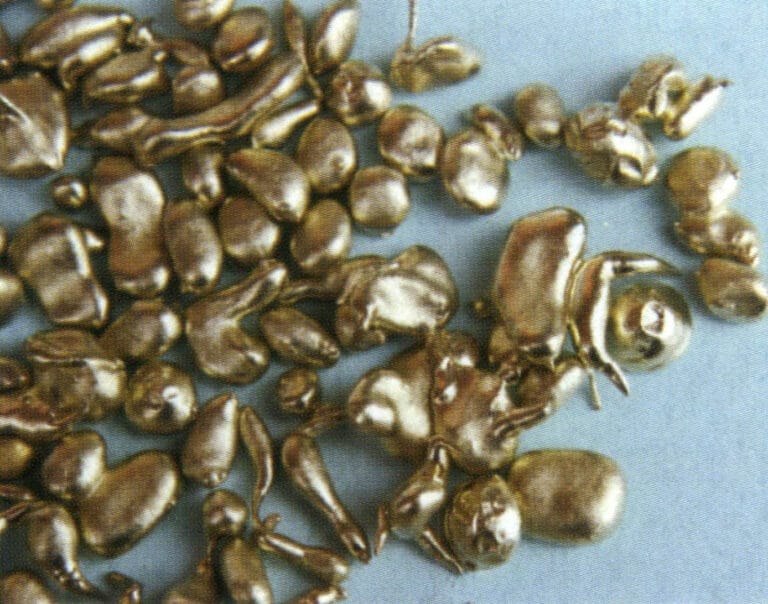
Figure 2-23 Cupronickel Granules
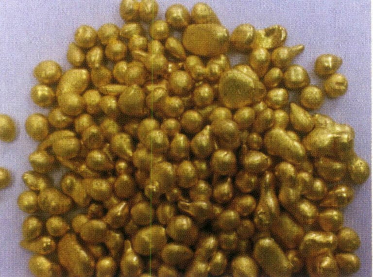
Figure 2-24 Bronze particles
(2) Alloy Smelting
The common melting methods for jewelry alloys are divided into two main categories: torch melting and induction melting.
① Torch smelting. Torch smelting to cast jewelry is a traditional production method using simple tools and equipment. First, the metal is melted using flames and then manually cast using simple pouring equipment. The combustion gases used in torch smelting include gas and oxygen, natural gas and oxygen, etc. Generally, oxygen-acetylene is not used because its temperature is too high, leading to significant metal loss and difficulty in control.
The smelting of torches generally uses clay crucibles. Before smelting, carefully check the quality of the crucible; the inner wall should have a smooth and dense glazed layer with no residual slag. Prepare the flux for slag formation, usually using anhydrous borax. First, preheat the crucible, then add copper particles, adjusting the flame intensity and nature to suitable levels. When the copper material is close to melting, sprinkle a small amount of borax on the liquid surface and gently stir the molten metal evenly with a glass rod (Figure 2-25). When the temperature reaches the required pouring temperature, the mold can be taken out for pouring.
During the smelting process, control the temperature and flame atmosphere; otherwise, serious oxidation will occur, leading to metal loss and slag contamination of the molten metal, especially in brass alloys, which are prone to significant zinc oxidation loss. The smelting temperature is generally controlled between 980~1020℃ to reduce metal loss and avoid prolonged.
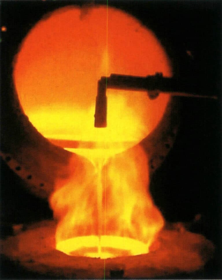
Figure 2-25 Torch smelting of copper alloys
② Induction melting. In the production of copper jewelry, the induction melting method is widely used to melt copper alloys (Figure 2-26). The control of the atmosphere during melting significantly impacts the quality of the molten metal. Generally, several methods exist, such as vacuum melting, inert gas protection melting, and reducing flame protection melting. Vacuum melting is beneficial for metallurgical quality; however, it is not suitable for copper alloys, especially brass alloys with high zinc content, because the vacuum exacerbates the volatilization of zinc, leading to severe metal loss, significant composition fluctuations, and the melting fumes can easily damage the vacuum system. Therefore, inert gases such as argon and nitrogen or reducing flames are generally used to isolate and protect the molten metal surface to achieve excellent metallurgical quality when induction melting copper alloys.
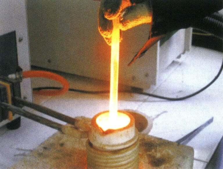
Figure 2-26 Induction Melting of Copper Alloys
(3) Pouring
Because jewelry pieces are relatively delicate, solidification occurs quickly during the casting process, resulting in a loss of fluidity. Therefore, conventional gravity casting struggles to ensure proper shaping, and it is necessary to introduce some external force to promote the rapid filling of the mold cavity with molten metal, achieving castings with complete shapes and clear contours. Based on the method of using external force, it can be divided into two main categories: centrifugal casting and static casting; based on the degree of automation in the casting process, it can be divided into manual casting machines and pressure casting machines.
① Manual pouring. Manual pouring is generally carried out with torch or induction melting. After the metal liquid is smelted and refined, the temperature is adjusted to the pouring temperature range. Then, the mold is removed from the burnout furnace to prepare for pouring. Depending on the type of equipment used, manual pouring mainly includes centrifugal casting and vacuum suction casting.
Figure 2-27 is a simple mechanical transmission centrifugal machine in some small jewelry processing factories. It does not come with an induction heating device, uses gas-oxygen to melt metal, or uses an induction furnace to smelt metal and pour it into a crucible. The gypsum mold is placed flat in the rotating arm’s mold base, and the rotating arm is started. Under the action of centrifugal force, the molten metal enters the mold cavity, completing the pouring process. Many factors affect quality during the operation, making it suitable for pouring small jewelry items, such as links, ear studs, etc.
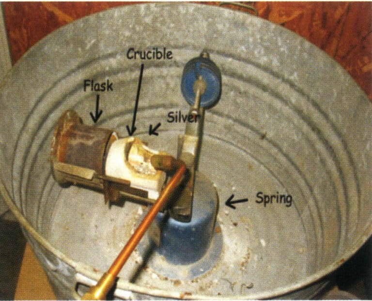
Figure 2-27 Simple Centrifugal Casting Machine Manual Pouring
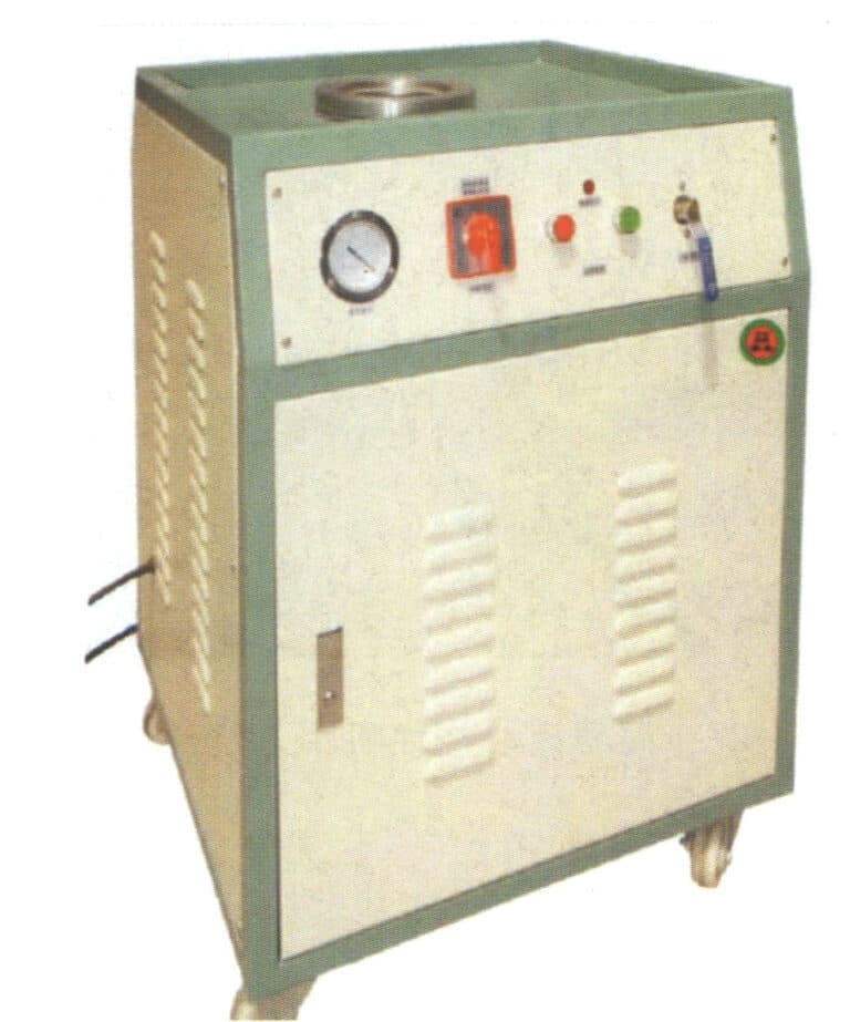
Figure 2-28 Manual pouring with the suction machine
② Automatic pouring of casting machines. With the increasing quality requirements for jewelry products and the technological advancements in the jewelry industry, automatic casting machines have become very important equipment in the lost-wax casting of jewelry, serving as an important foundation for ensuring product quality. Based on the type of external force used, the commonly used jewelry casting machines are divided into two categories: centrifugal and static casting.
In response to the shortcomings of traditional simple centrifugal casting machines, modern centrifugal casting machines integrate induction heating and centrifugal casting, achieving significant advancements in drive technology and programming, improving programming capabilities and process automation control. Figure 2-29 shows a typical melting and casting chamber of a jewelry centrifugal casting machine, which can be used for casting copper alloy jewelry.
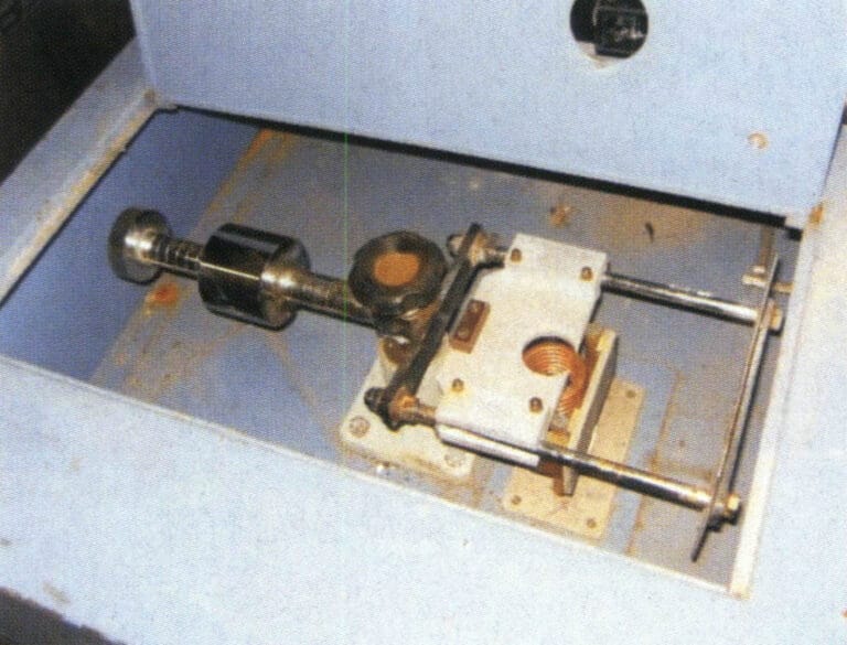
Figure 2-29 Automatic pouring of centrifugal induction casting machine
The most advanced and widely used static casting machine is the automatic vacuum pressure casting machine (Figure 2-30). There are many models of this type of machine, and the casting machines produced by different companies each have their own characteristics. Still, they generally consist of induction heating, vacuum systems, control systems, etc. In terms of structure, they are generally upright, with the upper part being induction chamber, the lower part being a vacuum casting chamber. The bottom of the crucible has a hole, which is sealed with a refractory plunger rod during melting. When pouring, the plunger rod is lifted, and the molten metal is poured into the mold cavity. Generally, a thermocouple is installed inside the plunger rod, which can accurately reflect the temperature of the molten metal. Automatic vacuum casting machines typically melt and cast metals under vacuum or inert gas atmospheres, reducing the possibility of metal oxidation and gas absorption. They are widely controlled by computer programming, have a high degree of automation, and produce stable quality castings with reduced porosity defects, making them highly regarded by many manufacturers. This equipment is used in small quantities for casting copper jewelry with low zinc content, while for copper alloys with high zinc content, it is generally used less frequently to avoid damaging the vacuum system.
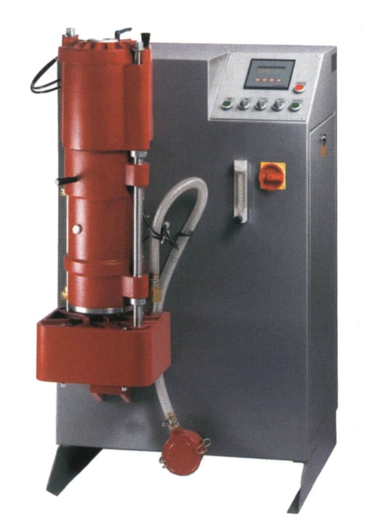
Figure 2-30 Automatic pouring of vacuum pressure casting machine
1.7 Casting Cleaning
After the casting is poured, it is left for about 15 minutes; then, the mold is quenched in water to perform the explosive gypsum operation. The residual heat of the casting powder mold encounters the cooling water, causing the water to vaporize instantly, resulting in an explosive powder phenomenon that separates the cast workpiece from the casting powder mold.
Use a high-pressure water jet to wash away the residual casting powder on the surface of the workpiece. The washed workpiece is generally black. Soak the washed casting in a water solution of hydrofluoric acid, sulfuric acid, or hydrochloric acid. The acid soaking thoroughly removes the residual casting powder from various parts of the casting and the oxidized inclusions on the surface of the casting. When soaking copper jewelry in hydrofluoric acid solution, the concentration is about 5%, and the soaking time is about 20 minutes.
After removing the casting powder, the workpiece is still in a tree-like shape and needs to be cut at its sprue, classified, and sorted by type to prepare for the next process. First, weigh the tree-like blank after removing the casting powder, calculate the loss during the casting process, and then perform the sprue cutting operation.
1.8 Post-processing of Castings
To achieve various surface effects for jewelry and to inlay different types of gemstones, post-processing of the castings is crucial. Typically, it involves several main processes: mechanical polishing, finishing, setting, and surface treatment (such as polishing, electroplating, coloring, etc.). Below is a brief introduction to these main processes.
(1) Finishing
The finishing process is the integration, fitting, welding, and rough surface processing of jewelry blanks, restoring them to their original model. The finishing procedure is an important step in the jewelry-making process. The quality of jewelry will be directly affected if the finishing process is not well executed. According to jewelry products’ categories and structural characteristics, they can be divided into several typical types, such as rings, earrings, chains, and bracelets. Their finishing processes are not the same, but they generally go through the following procedures.
① Shaping. Restore the workpiece to its original model and standard dimensions.
② File the sprue. First, use a coarse file to smooth the sprue and surface, then use a smooth file to repair various parts of the workpiece to make it smooth (Figure 2-31).
③ Assemble welding or weld repair sand holes. Weld the fittings in the appropriate position on the workpiece, serving as decoration or fixing the assembled workpiece (Figure 2-32). When sand holes appear on the workpiece, use solder for repair.
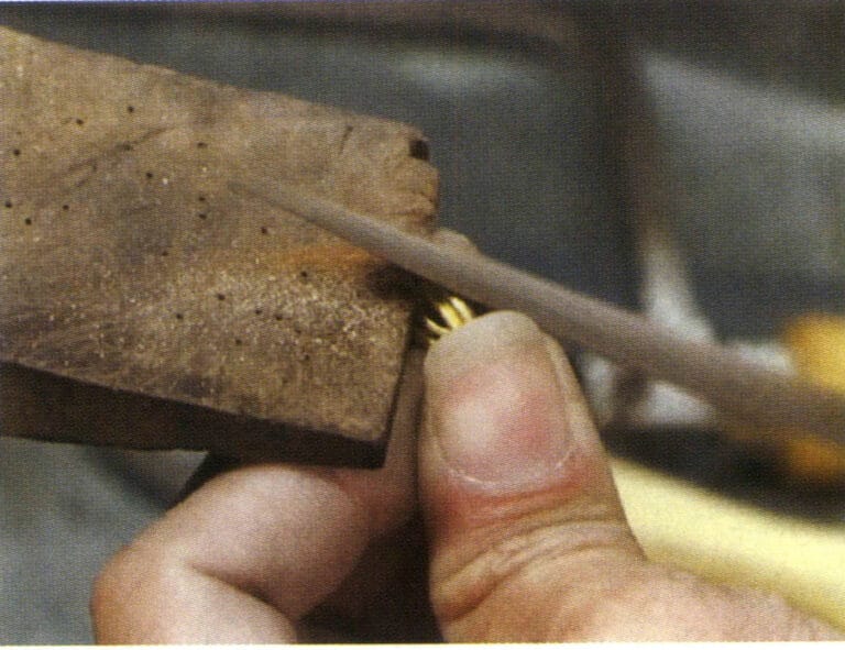
Figure 2-31 Water sprue
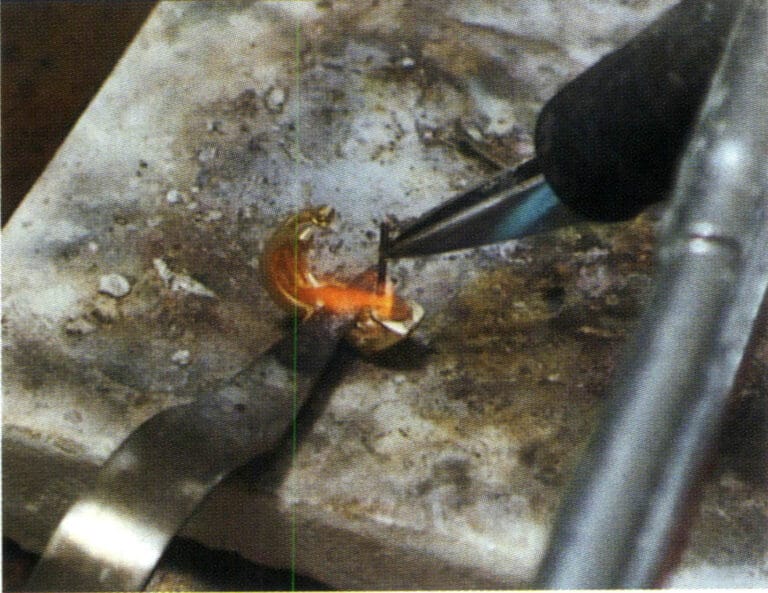
Figure 2-32 Assembly Welding
④ Boiling in alum solution. After welding, the workpiece will form a black-gray substance on the surface, which can be removed after boiling in alum water to clean the impurities on the surface of the workpiece (Figure 2-33).
⑤ Filing the surface. Use a sliding file to grind the inner circle, outer circle, and side of the ring to make the surface smooth and free of burrs, with a smooth shape.
⑥ Sandpaper polishing. Sandpaper removes the workpiece’s file marks, making the workpiece’s surface smooth (Figure 2-34).
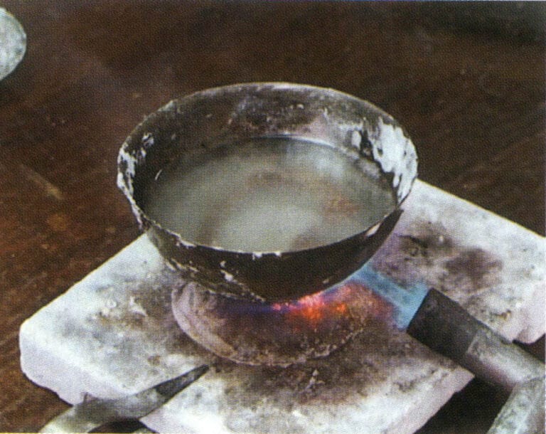
Figure 2-33 Boiling in alum water
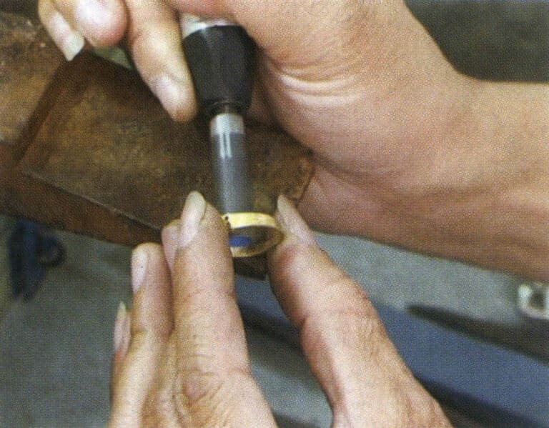
Figure 2-34 Sandpaper polishing
(2) Πέτρες τοποθέτησης
Setting craftsmanship is a technical method that combines gemstones of different colors, shapes, and textures through extensive setting, filing, carving, chiseling, and welding to create various shapes and styles, giving them a high appreciation value as crafts and decorative items.
Common inlay methods mainly include inverted pave setting, prong setting, flush setting, Italy setting, pavé setting, channel setting, and invisible setting. The overall process of stone setting is divided into three main steps: preparation before setting, setting operation, and surface finishing after setting.
① Preparation work before setting stones. Mainly divided into two steps: selecting stones and applying fire lacquer.
Selecting stone: It involves checking the quality, quantity, and weight of various specifications of gemstones according to the order to see if they meet the requirements. Then, they are screened and classified, and the gemstones are allocated according to the customer’s order quantity for the setting department to arrange production.
Applying fire lacquer: It is to fix the workpiece on the fire lacquer handle, making it easier for the operator to hold and manipulate during the stone inlaying process. Mostly used for earrings, pendants, and other inlaid pieces; other inlay methods depend on the specific processing requirements of the goods.
② Setting operation. The setting operation is generally divided into five basic steps: measuring stone position, polishing stone position, placing the stone, fixing the stone, and repair. The main inlay methods include prong setting, pave setting, channel setting, flush setting, bezel setting, invisible setting, etc. Taking prong setting as an example, its operation steps are shown in Figure 2-35.
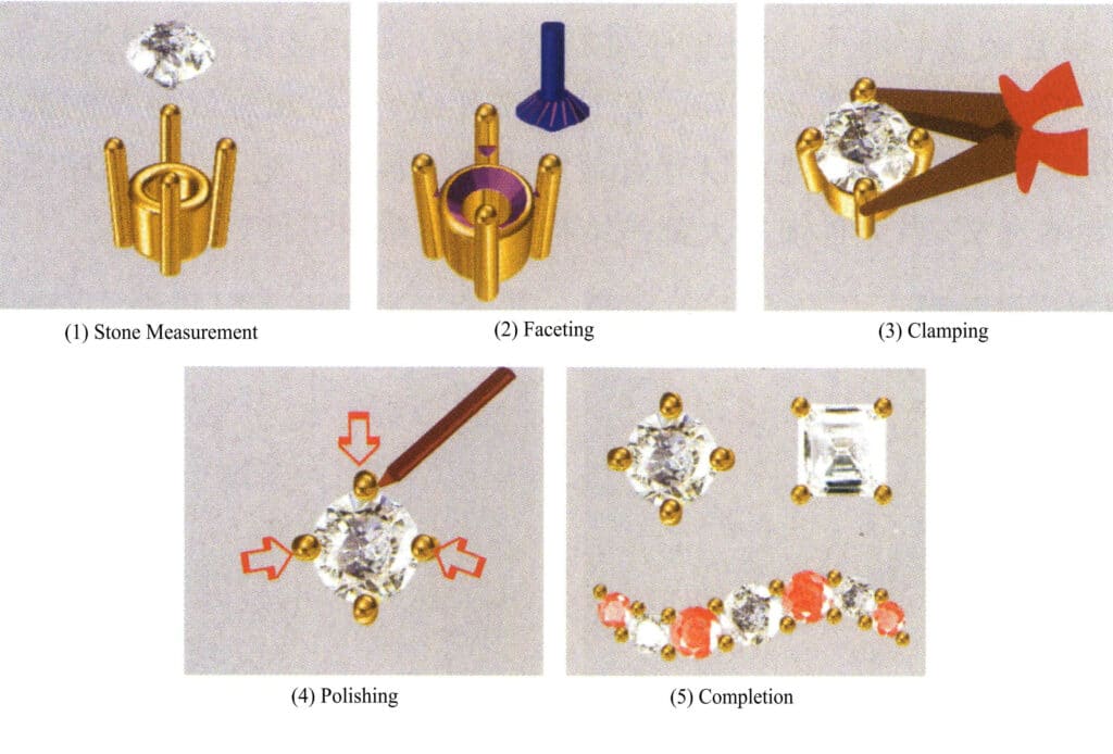
Figure 2-35 Schematic diagram of prong setting operation process
③ Surface finishing. It mainly includes three steps: washing the fire lacquer, edge finishing, and edge scraping.
Washing the fire lacquer involves using a torch to bake the wax on the workpiece after the stone is inlaid, then removing the workpiece and soaking it in turpentine to clean the wax.
Edge finishing: It is the process of using tools such as files, machine burs, and sandpaper to smooth the rough surface of the workpiece, restoring the surface of the workpiece after stone setting to a smooth and soft state.
Edge trimming: It is the process of leveling the burrs on the inner side of the workpiece’s gold edge after bezel setting, channel setting, and flush setting, making the inner edge lines smooth and the surface bright.
(3) Surface Treatment
There are many surface treatment methods for copper alloy jewelry, and electroplating is one of the most commonly used surface treatment methods. It generally includes three main stages: pretreatment, electroplating, and post-treatment.
① Preprocessing. Polishing is a key process to achieve the best appearance effect for jewelry. Commonly used equipment includes ordinary polishing machines and disc polishing machines, with ordinary polishing machines being of two types: simple and recycling. When the polishing wheel rotates at high speed, high temperatures are generated between the jewelry, the polishing wheel, and the molten buffing compound, which enhances the plasticity of the metal, improves the fine unevenness of the surface, and increases the brightness of the jewelry (Figure 2-36). The effect of polishing mainly depends on the characteristics of the surface to be processed, that is, the degree of polishing and leveling of the workpiece surface, as well as the type and characteristics of the polishing materials used during the polishing process. Polished jewelry should achieve a smooth, flawless finish, symmetrical shapes, smooth lines, uniform thickness, rounded edges, and corners, and be free of issues such as broken prongs or loose stones.
The surface of jewelry that has been polished almost inevitably adheres to wax or oil stains, and it needs to undergo a degreasing treatment before electroplating. Common degreasing methods include ultrasonic degreasing and electrochemical degreasing. Ultrasonic degreasing can further enhance the speed and effectiveness of solvent and chemical degreasing, has minimal corrosion on the substrate, and offers high degreasing and purification efficiency, making it particularly effective for complex workpieces with fine holes and blind holes. Ultrasonic cleaning machines have become an indispensable piece of equipment in jewelry making (Figure 2-37). In the past, cleaning dead corners, blind holes, and hard-to-reach areas has been a difficult problem, but ultrasonic cleaning can effectively solve this issue. This is particularly significant for jewelry, as most pieces are complex and finely structured workpieces.
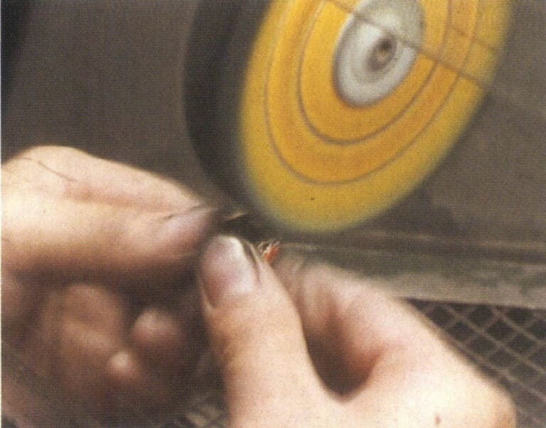
Figure 2-36 Cloth Wheel Polishing
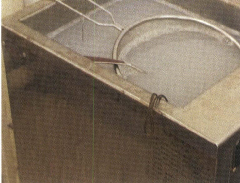
Figure 2-37 Ultrasonic Grease Removal
Electrochemical degreasing involves hanging the jewelry on the cathode or anode of an alkaline electrolyte (Figure 2-38). During electrolysis, the bubbles escaping from the surface of the jewelry have a strong tearing effect on the grease film on the surface, and the agitation caused by the rising bubbles continuously carries away the oil, further enhancing the degreasing effect. The speed of electrochemical degreasing exceeds that of chemical degreasing, resulting in good effectiveness.
Jewelry must be cleaned and weakly etched before entering the electroplating tank. The purpose of cleaning is to remove the adhering liquid on the surface of the jewelry, promote the deposition of metal ions, and avoid contaminating the electroplating solution. Copper jewelry is generally cleaned before plating using a multi-stage countercurrent cleaning production line, as shown in Figure 2-39. The main purpose of etching is to neutralize any alkaline solution that may remain on the surface of the workpiece, dissolve the oxide film on the surface of the workpiece, and activate the surface to ensure a strong bond between the plating layer and the base metal. The concentration of the etching solution is generally quite dilute, 1%~5%, and will not damage the surface finish of the material, with the time usually only a few seconds to 1 minute.
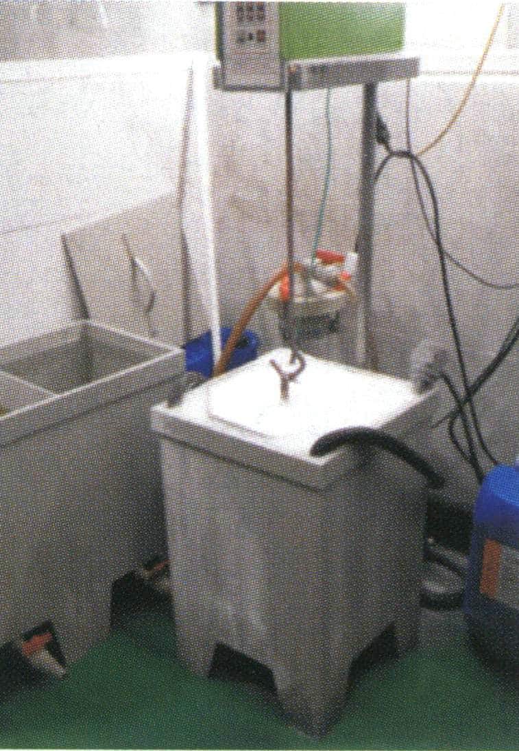
Figure 2-38 Electric De-oiling
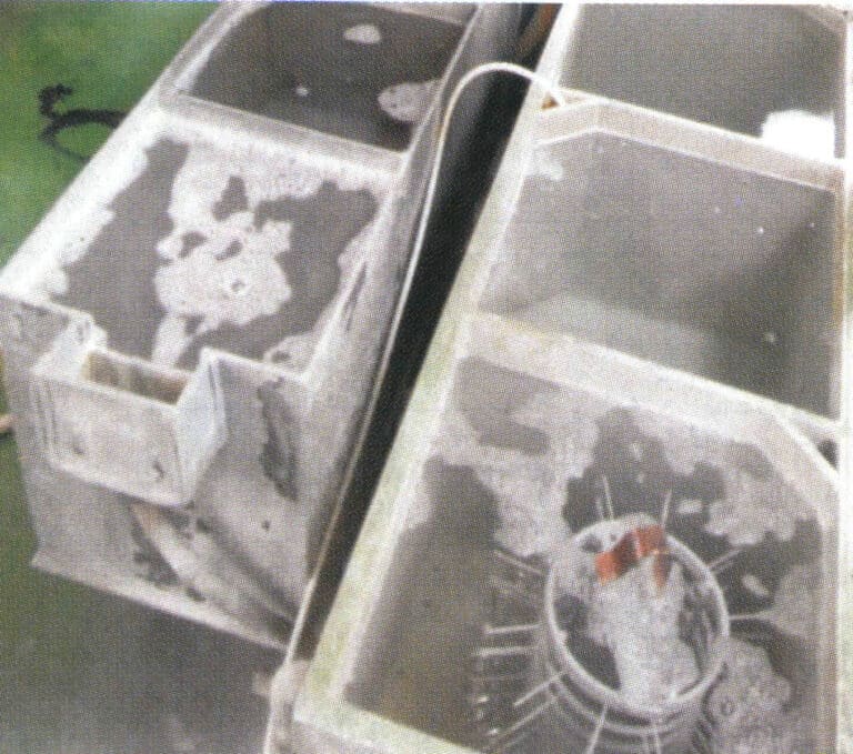
Figure 2-39 Pre-plating cleaning
② Electroplating operation. The surface electroplating of copper jewelry generally includes several methods, such as silver plating, gold plating, and rhodium plating. When gold plating or rhodium plating, a layer of nickel is usually pre-plated on the surface of the jewelry. During production, it is necessary to regularly monitor the electroplating solution in the plating tank and various key material indicators to prevent mismatches in indicators, which could lead to product quality issues.
③ Post-plating treatment. The workpiece, after electroplating, is first dipped in a plating solution recovery cup, rinsed with water, soaked in hot pure water, then rinsed with a steam washing machine, and finally dried with a hot air gun.
2. The Stamping Process of Copper jewelry
The stamping process is widely used in producing copper jewelry, especially white ones, most of which use the stamping process. The process is very similar to that of stainless steel stamped jewelry; for details, see the introduction in other articles.
3. The Electroforming Process of Copper jewelry
3.1 Introduction to Electroforming Technology
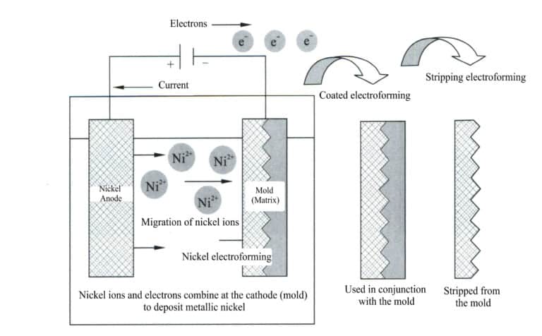
Figure 2-40 Electroforming Schematic
Use the original mold made in the desired shape as the cathode and the electroforming material as the anode, and place them together in a metal salt solution that is the same as the anode material, applying direct current. Under the action of electrolysis, the metal electroforming layer is gradually deposited on the surface of the original mold and reaches the desired thickness, it is removed from the solution, and the electroforming layer is separated from the original mold, thus obtaining a metal replica corresponding to the shape of the original mold.
Compared to the lost-wax casting process, electroforming can produce larger workpieces with very thin walls, making it particularly suitable for crafting decorative items. The main disadvantage of electroforming is its low efficiency, with the thickness of the electroformed metal layer generally being 0.02~0.05 mm per hour. By using a high-concentration electroforming solution appropriately, increasing the solution temperature, and enhancing stirring, the current density can be improved, reducing the electroforming time and thereby increasing the efficiency of electroforming.
3.2 Electroforming Process of Copper jewelry
The typical electroforming process for copper jewelry includes sculpting the mold, replicating the mold, wax mold injecting, wax mold finishing, applying silver plate, electroforming, finishing, wax removing , and polishing.
(1) Wax Mold Making
Making wax molds involves designing wax material, sculpting the mold, replicating the mold, wax molds injecting, and wax molds finishing. When making large workpieces, clay carving templates are also used, which are copied into silicone and wax molds.
① Sculpting the wax mold. Carved into a wax template using high relief, low relief, openwork, and line carving techniques. First, initial rough carving is performed, which is done according to the design intent and process conditions, using carving tools to shape the wax material into a certain form to determine its basic shape; after the initial rough process, fine carving and detailed finishing are carried out to address various shortcomings from the previous steps and to make the surface of the wax mold smooth and polished.
② Replicating molds. Copy the qualified carved wax model into a rubber mold to achieve the purpose of mass production.
For small copper jewelry, first, fix the wax model on a glass surface, surround it with sandpaper, leaving a certain distance between the model and the sandpaper tube, then vacuum the uniformly mixed silicone and inject it into the sandpaper tube (Figure 2-41), then vacuumed, and glue is injected according to the actual situation. After filling it with silicone, please place it in the vacuum machine to vacuum, and put the last vacuumed sandpaper tube in a suitable and stable position to let it dry naturally.
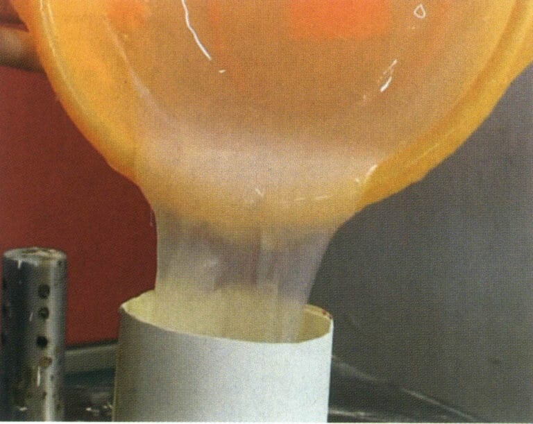
Figure 2-41 Replicating rubber mold
For large copper ornaments, the method of first applying glue on the template and then using plaster for replication is generally adopted. Fix the model on a disc, and use a brush to apply the prepared silicone on the template. After the first layer is qualified, repeat the brushing two more times until the thickness reaches 3~5 mm. Use the oil clay to fill the larger concave hole. Then, use the right amount of water to mix a good plaster paste, with a flat shovel and hand (wearing rubber gloves) scraping and wiping plaster mud on the mold plate, a thickness of about 20 ~ 30mm. Scraping and wiping, depending on the complexity of the shape of the model, is broken down into several parts of the production, divided into two pieces, complex divided into 3 ~ 4 or several pieces, to facilitate the removal of the rubber mold and the model. After the work, the entire mold is placed to dry naturally, with a rubber hammer to knock the decomposed plaster layer.
③ Mold cutting. Use a scalpel to cut the silicone layer at the appropriate position and remove the model. When cutting the mold, choose areas that are easy to repair so that the poured wax mold is easy to finish (scrape) on the plate. Avoid cutting through the facial features of sculptures of people or animals. After cutting the mold, check the quality of the silicone mold to see if there are any bubbles and whether the silicone molds fit together tightly. For large decorative items, close the cut silicone mold, use plaster to decompose the mold to hold the silicone mold together, fix it, and then use glue lines and glue tape to secure it tightly.
④ Wax mold injecting. Use the gas from an air compressor to blow away impurities inside the rubber mold, then place the mold in an electric oven to preheat for about 5 minutes, allowing the mold’s temperature to reach 60~65℃ and remove moisture. Remove the mold from the oven, close it, and ensure the joints are completely sealed, securing them with rubber bands. Use an iron spoon to scoop the wax from the electric heating tank and pour it into the rubber mold (Figure 2-42), then place it in a vacuum-vibrating machine to vacuum for 1~2 minutes, remove the wax supplement, and vacuum again for 1~2 minutes. After completing the injecting, supplementing, and vacuuming, place the rubber mold on the workbench to cool naturally. Once the pouring opening has solidified, stand the mold in a plastic basin filled with cold water to accelerate the wax solidification. The solidification time depends on the volume of wax, generally over 30 minutes and sometimes up to 1 day. Once the wax model inside the rubber mold has completely solidified, loosen the rubber bands and tape and open the rubber mold to remove the wax figure.
⑤ Wax mold finishing. Use a wax scraper or surgical knife to remove the flash, wax marks, sprues, etc., from the wax mold (Figure 2-43), and make the entire surface of the wax mold beautiful and smooth. Use an electric soldering iron to dot wax to fill small holes and other defects on the wax mold or connect several wax parts. Wipe the surface of the wax mold with gasoline to make it clean and smooth.
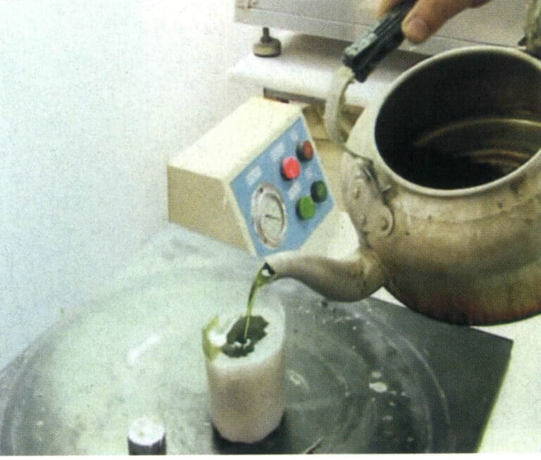
Figure 2-42 Wax mold injecting
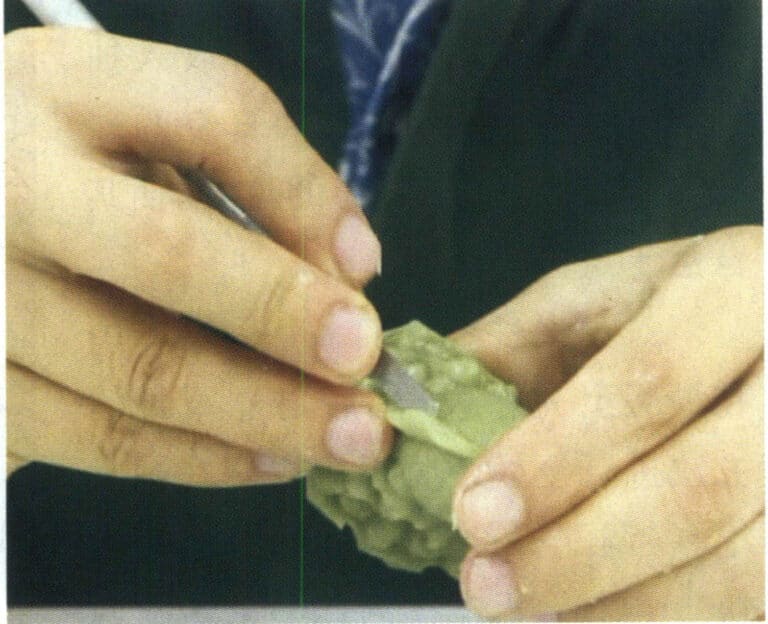
Figure 2-43 Wax mold finishing
(2) Electroforming
Hollow electroforming is the process of hollow electroforming jewelry pieces based on a wax mold, using silver plate coating and electroforming technology. For larger pieces and those with special requirements, electroplating is also needed for the surface processing treatment.
① Insert hanging rods. Hanging rods must be inserted into the wax mold to facilitate the electroforming of the casting tank and achieve fixation and conductivity.
② Apply silver plate (conductive layer). Since the wax mold is not a conductive material, a uniform layer of silver plate must be applied to the surface of the wax mold. During the natural drying process of the silver plate, the acetone in the solvent evaporates, and a very thin conductive layer is formed on the surface of the wax mold, thus preparing for the electroforming process (Figure 2-44).
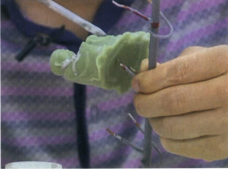
Figure 2-44 Silver Plate Coating
③ Open reserved holes. To remove wax and silver plate and ensure the purity of the metal in the ornament, it is necessary to leave reserved holes for post-processing. This avoids increasing metal loss and the likelihood of product scrap due to opening holes in the finished product. Opening reserved holes should follow two points: first, it should not affect aesthetics and should be placed in a relatively concealed position; second, the quantity and size should be appropriate. Therefore, it must be coordinated with various processes such as wax carving, engraving characters, inserting rods, and post-processing, and cannot be done independently.
④ Weighing. Place the wax mold with the iron hanging rod on the electronic scale to understand and control the weight of the casting.
⑤ Place the mold into tank for electroforming. The wax mold must be cleaned with pure water before placed into tank to remove dust from the surface; otherwise, the casting may develop perforations due to dust. Areas with more recesses in the wax mold should face the metal mesh of the casting cylinder, which ensures a faster-pouring speed in the recesses and a more uniform casting layer. Otherwise, the pouring speed in the recesses will be slow, resulting in a thin casting layer after demolding, which may lead to perforations during grinding and wax removal.
At the expected start time, take out the casting for weighing. If the weight meets the required range, it can be started and cleaned, and then the hanging rod from the casting can be registered and handed over to the next process operation.
(3) Surface Treatment
Copper electroformed parts generally require gold plating on the surface. For plush sand products, a thin layer of gold is usually plated immediately after copper electroforming. The gold plating process occurs after surface treatment of the copper electroformed parts for water and products. Typical surface treatment tasks include finishing, drilling, wax removal, polishing, and gold plating.
① Finishing. Perform preliminary treatment on the cast surface to remove burrs.
② Wax removal. Remove the wax inside the casting to make the casting a complete metal body, a hollow, multi-layered jewelry craft casting.
First, place the jewelry in the 150~300 ℃ electric oven for 20~30 minutes to burn out the wax from the jewelry. Remove it while hot and place it in the ultrasonic wax removal machine to eliminate any remaining wax. After removing the wax, remove the jewelry and pour the water inside, then place the casting in the ultrasonic cleaning machine for cleaning. Rinse the surface of the casting with tap water, use an air gun to blow away the water droplets inside and outside the casting, and let it air dry naturally on the workbench.
③ Baking in the oven. After cleaning the surface of the accessory, please place it in the oven of 750℃ for about 10~20 minutes to bake at degrees to remove moisture and impurities in the sand, preventing the appearance of red spots, eliminating internal stress, and changing the brittleness of the accessory.
④ Polishing. Polishing certain areas of the castings to make the product appear more striking, dazzling, and noble.
⑤ Gold plating. The main purpose is to enhance the surface protection of the workpiece and prevent discoloration of the workpiece surface. The workpiece is placed in a chemical degreaser and cleaned in an electro-degreasing tank to remove surface oil. After cleaning the water, the gold plating operation is performed.