Rhino, 플라밍고, 테크젬으로 주얼리 렌더링을 만드는 방법? 그리고 일부 디지털 페인팅의 미학적 검토
Rhino 3D, 플라밍고, 테크젬과 주얼리 디자인 효과의 이해
소개:
멋진 3D 렌더링으로 주얼리 디자인에 생명을 불어넣을 수 있다면 어떨까요? 이 가이드에서는 Rhino 3D, Flamingo, TechGems를 사용하여 전문적인 주얼리 렌더링을 만드는 방법을 보여드립니다. 주얼리 디자이너에게 이러한 도구가 필수적인 이유와 섬세한 펜던트, 팔찌 등을 제작하는 방법을 익히는 방법을 알아보세요. 모델링에는 Rhino를, 렌더링에는 Flamingo를, 사실적인 보석을 추가하는 데에는 TechGems를 사용하는 단계별 과정을 살펴보세요.
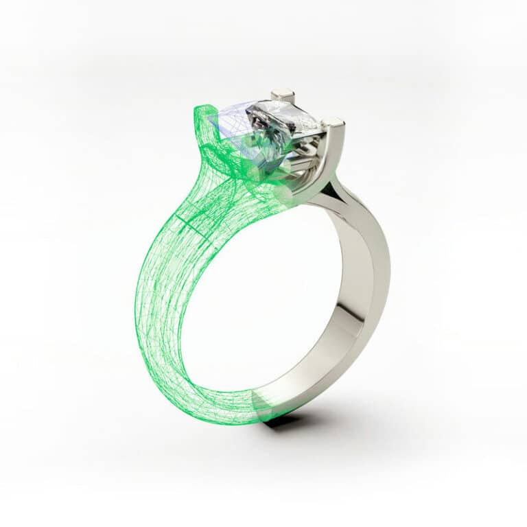
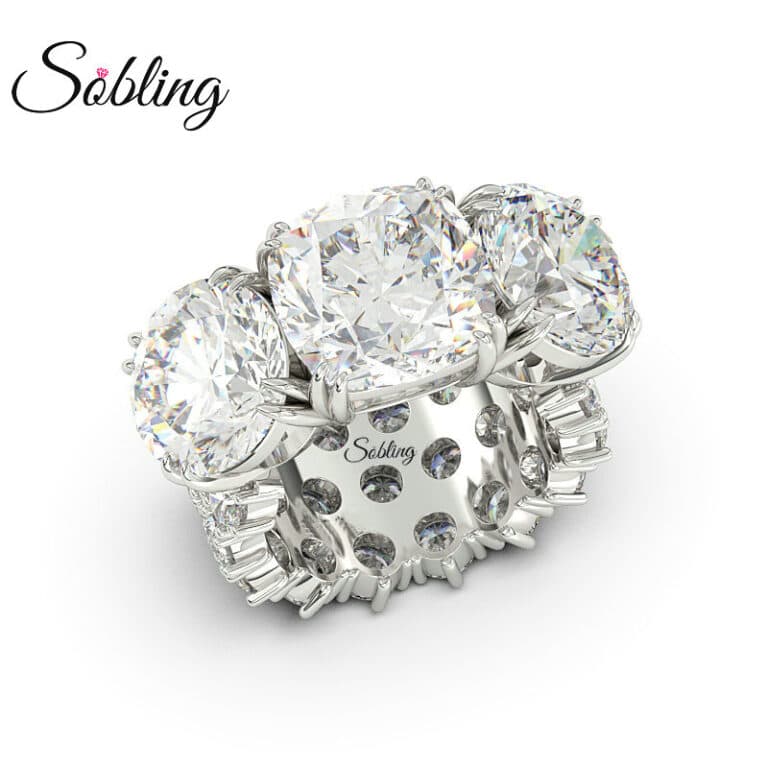
최종 렌더링
목차
섹션 I Rhino로 주얼리 디자인 렌더링 만들기
1. Rhino 3D 배우기
전문 산업 디자인 소프트웨어인 Rhino는 현재 가구, 전자, 자동차, 항공우주, 주얼리 등 다양한 산업 분야에서 널리 사용되고 있습니다. 모든 분야의 디자이너가 반드시 익혀야 하는 소프트웨어 기술이 되었습니다. 배우기 쉽고 조작이 편리하며, 그 원리는 가장 널리 사용되는 정밀한 NURBS 서피스 원리를 기반으로 합니다.
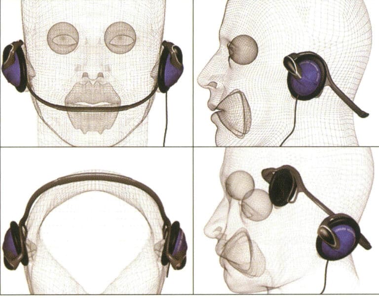
NURBS는 국제적으로 인정받는 산업 등급의 정밀 설계 표준입니다. 폴리곤 메시 모델과의 차이점은 NURBS 서페이스는 모양을 제약하는 과도한 메시 와이어프레임 없이 곡률과 곡선 정밀도에 따라 모델을 구성할 수 있다는 것입니다. 따라서 부동 소수점 연산 횟수를 절약할 수 있으며 최소한의 NURBS 커브 조합으로도 충분히 정확한 서페이스를 얻을 수 있습니다. NURBS 표면은 렌더링 중에 매우 높은 렌더링 해상도로 설정할 수 있으며, 이는 메시와는 다릅니다.
Rhino
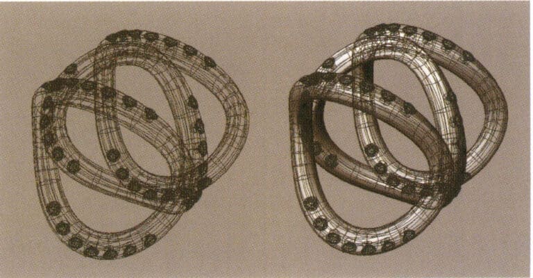
Rhino의 NURBS 서페이스
Rhino의 사용자 인터페이스
Rhino의 인터페이스는 3D Studio MAX, AutoCAD, Maya, Softimage와 같은 다른 3D 소프트웨어와 유사합니다. 아래 표와 같이 크게 다섯 가지 영역으로 나뉘며, 각 영역은 용도에 맞게 사용됩니다:
Rhino의 인터페이스 영역
| 인터페이스 영역 | 지침 |
|---|---|
| 메뉴 | 명령, 옵션 및 도움말 파일로 작업하기 |
| 도구 모음 | 명령 및 옵션 사용 단축키 |
| 조회수 | 도면에서 3D 모델과 2D 곡선을 다양한 보기로 표시하기 |
| 명령줄 | 실행된 명령 및 해당 정보 목록 |
| 상태 표시줄 | 입력 포인트의 좌표, 개체 상태, 토글 선택 항목 표시하기 |
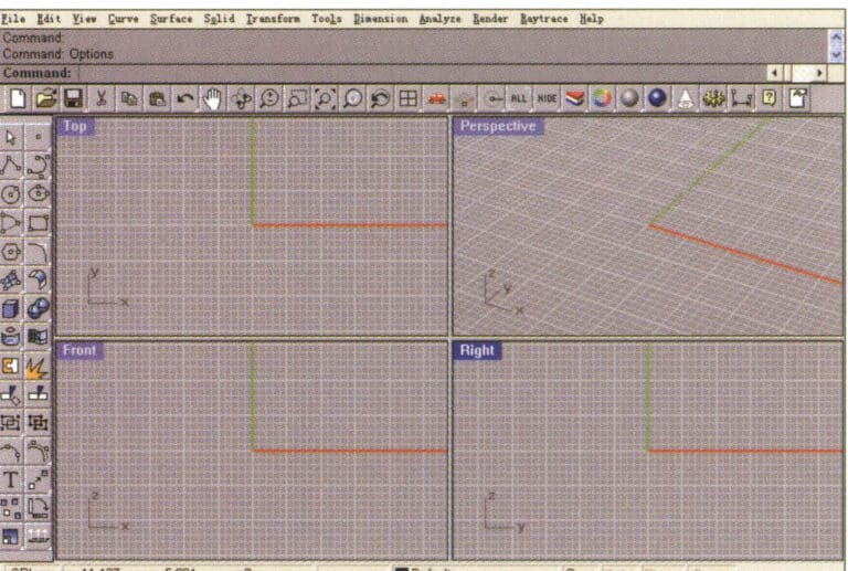
Rhino의 운영 인터페이스
(1) 메뉴
메뉴는 인터페이스의 맨 위 레이어에 있으며, Rhino의 대부분의 명령은 드롭다운 메뉴로 배열되어 있습니다. 명령을 실행하려면 명령 항목을 직접 클릭합니다. 작업은 다음과 같습니다:
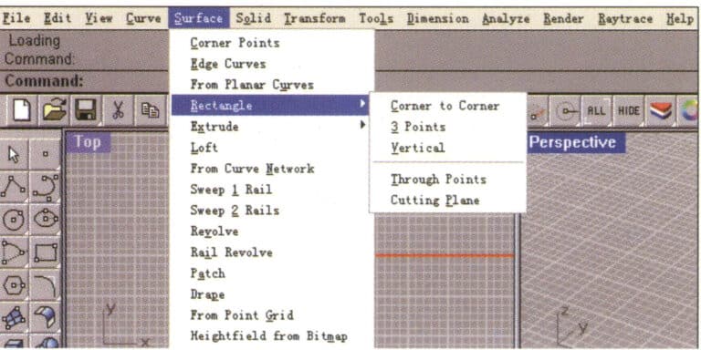
Rhino 메뉴
(2) 도구 모음
Rhino의 도구 팔레트에는 명령을 빠르게 실행할 수 있는 단추가 있습니다. 부동형 도구 팔레트를 뷰의 아무 곳에나 배치하거나 드로잉 영역의 가장자리에 도킹할 수 있습니다.
Rhino가 시작되면 드로잉 영역의 상단에 일반 도구모음(저장과 보기 제어 버튼 등)이 포함되고, 드로잉 영역의 왼쪽에 편집 도구모음(선택과 복사 버튼 등)이 포함될 것입니다.
도구 설명의 역할은 각 도구의 이름과 기능을 표시하는 것입니다. 커서를 움직이지 않고 도구 버튼 위로 이동하면, 명령의 이름이 표시된 노란색 도구 설명이 나타납니다. Rhino에는 두 개의 명령을 실행할 수 있는 도구 단추가 많이 있으며, 도구 설명에는 두 명령의 바로 가기 키와 명령 이름이 표시됩니다.
드롭다운 도구 버튼이 있는 많은 도구가 도구 모음에 팝업으로 표시될 수 있습니다. 팝업 도구 모음의 도구는 일반적으로 같은 유형의 도구에 속하며 마우스를 클릭하면 버튼이 자동으로 접힙니다.
팝업 도구 버튼의 오른쪽 하단에 흰색 삼각형이 있습니다. 도구 모음을 팝업하려면 마우스 왼쪽 버튼으로 버튼을 길게 누릅니다.

프롬프트 상자

팝업 도구 버튼 및 팝업 도구 모음
(3) 보기
보기는 조작 중인 객체의 투영과 원근을 표시하는 영역입니다. 기본 설정은 상단, 전면, 오른쪽 및 원근으로 구분된 4개의 보기입니다. 보기 제목 표시줄 또는 가장자리를 드래그하여 보기 크기를 이동하거나 변경할 수 있습니다. 각 뷰에는 고유한 기본 평면과 투영 방법이 있습니다. 새 보기를 만들고 이름을 변경하거나 보기의 옵션을 재정의할 수 있습니다.
보기 제목 열을 마우스 왼쪽 버튼으로 두 번 클릭하여 작은 보기를 큰 보기로 전환하여 전체 그리기 영역을 채웁니다.
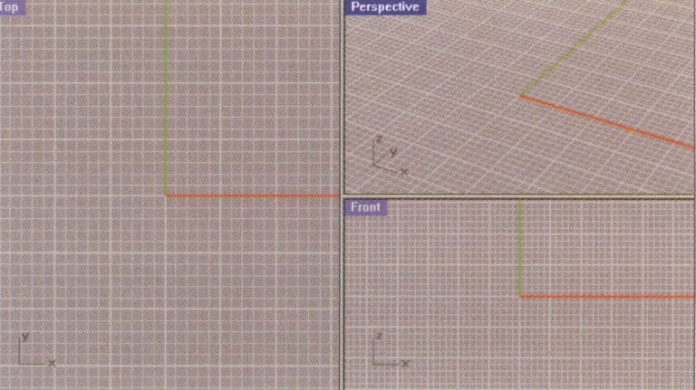
작은 보기를 큰 보기로 전환
(4) 명령줄
명령줄은 명령을 입력하거나 실행된 명령의 이름을 표시하는 영역입니다. 보기 영역의 위 또는 아래에 배치할 수 있습니다. 시스템의 기본 명령줄에는 세 줄의 명령이 표시될 수 있습니다.

명령줄
(5) 상태 표시줄
상태 표시줄은 인터페이스 하단에 표시되며, 입력 포인트 좌표, 개체의 상태, 토글 옵션 등을 표시하는 기능을 합니다. 상태 표시줄에는 현재 작업 범위로 스냅할 수 있는 강력한 기능도 있어 개체를 정확하게 설정하는 데 매우 유용합니다.
2. 플라밍고 배우기
Rhino 3D의 렌더링 시스템은 매우 제한적입니다. 3ds Max나 Maya와 같은 다른 3D 소프트웨어와 비교하면, 렌더링은 Rhino 3D에서 가장 취약한 부분입니다. 하지만, Rhino의 렌더링 문제를 걱정할 필요는 없습니다. 공식 Rhino 2.0이 출시되었을 때, AccuRender에서 출시한 렌더링 플러그인 Flamingo가 Rhino의 렌더링 기능을 보완하여 Rhino의 렌더링 시스템이 크게 향상되었고, 렌더링 품질도 놀라울 정도로 향상되었기 때문입니다.
Flamingo의 렌더링 시스템은 일반적으로 플러그인이라고 부르는 임베디드 모듈입니다. Flamingo는 Rhino 플랫폼에 임베드된 경우에만 사용할 수 있으므로 먼저 설치해야 합니다. 제가 여기서 사용하는 버전은 Flamingo 1.0이며, 왼쪽 이미지는 Flamingo의 주요 명령 아이콘을 보여줍니다.
Flamingo 렌더링 설정 시스템으로 들어갑니다. 렌더링 메뉴에서 속성 명령을 선택하여 문서 속성 패널을 열고, 문서 속성 메인 패널에서 플라밍고 옵션을 선택하여 각 렌더링 매개변수를 소개합니다.
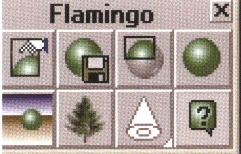
플라밍고 명령 아이콘
렌더러 플라밍고

State bar
(1) Resolution Options
Viewport resolution – provides the rendering size of the actual size of the operating view, related to the actual display size of the monitor and the size of the operating window; here, it is the system’s default mode.
Custom resolution – provides manual rendering size, allowing readers to adjust the rendering size according to their requirements. The system also offers three other commonly used sizes that can be set as needed.
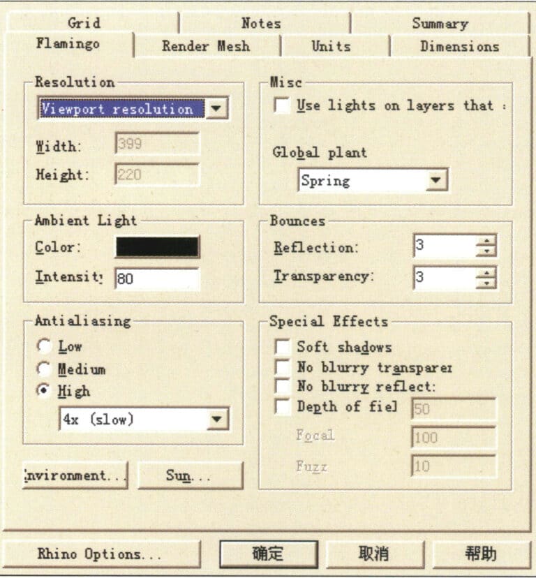
Flamingo rendering settings
(2) Misc Options
Use lights——provides built-in lighting in the system; check to turn it on.
Global Plant——global settings provide lighting for various climates.
(3) Ambient Light options
색상—-the color of light. By default, the system is set to black. Readers can adjust the corresponding color, and when the color changes, the rendering result will change according to the color of the light, as shown in below image.
Intensity—-the density of light. In simple terms, it refers to the strength of light. The system provides numerical changes; the larger the value, the stronger the color of the light. When the color of the light is black, it represents no light, and there is no change in the color and density of the light.
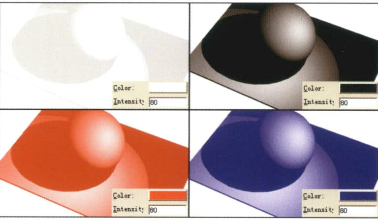
Color - The color of light

Intensity——The density of light
(4) Bounces Options
Reflection—- Reflection options. You can set the number of light reflections; the greater the refraction value of the light, the more times the light bounces within the object, which is most evident on transparent materials.
Transparency—-the number of light bounces. The higher the bounce value, the richer the colors and layers in the image, which is most evident on transparent materials. The bounce value is related to the reflection and refraction values, and the system provides manual adjustment for free control.
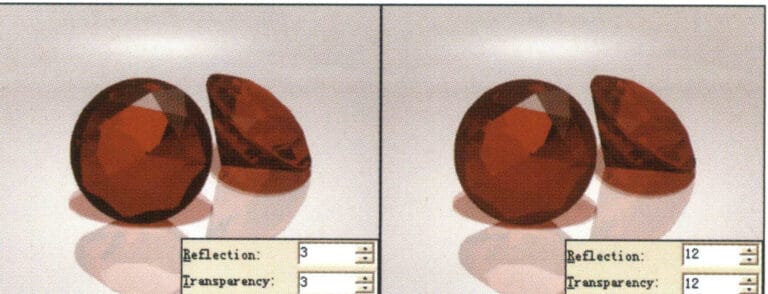
Bounces options
(5) Anti-aliasing Options
Low — Low anti-aliasing: Visible jagged edges in the image.
Medium — Medium anti-aliasing: Jagged edges are less noticeable.
High (4x) — High anti-aliasing (4x): Smoother edges (recommended for test rendering).
High (6x) — High anti-aliasing (6x): Smooth edges.
High (8x) — High anti-aliasing (8x): Very smooth edges (recommended for final rendering).
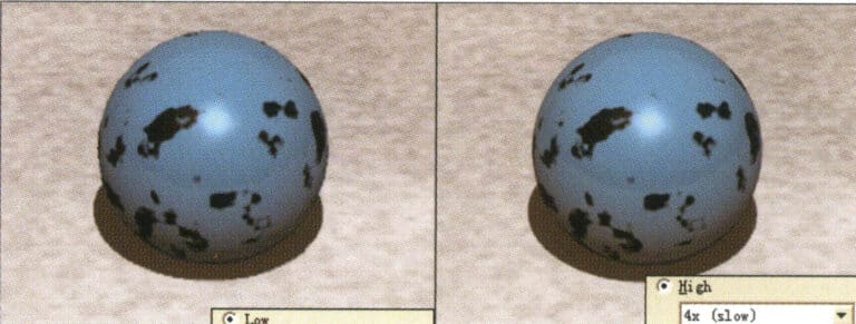
Antialiasing options
(6) Special Effects (Special Tools) Options:
Soft shadows: When unchecked, the shadows are hard, indicating direct lighting; when checked, the shadows are soft, indicating indirect lighting, enhancing the sense of weightlessness in the image, simulating the real shadows of objects in real life; when checked, rendering time is extended, do not enable during test rendering, please select according to requirements during final rendering.
No blurry transparent – When checked, no transparent blur is produced.
No blurry reflection – When checked, no transparent reflection is produced.
Depth of field – Depth of field option. Used to simulate the effect of reality between focus and blur. When checked, the rendering time increases geometrically; do not enable it during test rendering; please select according to requirements during final rendering.
Focal (camera focal length) – The value can be changed according to needs.
Fuzz (quality of blur) – The value can be changed according to needs.

Special Effects (Special Tools) options
(7) Environment Options
Background Color——Background Color Light Source:
Automatic Sky – Automatic Sky Light. The system customizes the skylight source, and the color of this light source cannot be modified here; it can only be changed under Ambient Light.
Solid Color (1 color light) – adjustable light source color, system default option.
2 Color Gradient (2 Colors of Light) – Provides two adjustable light source colors.
3 Color Gradient – Provides two adjustable light source colors.
(Changing the scene color can create variations in brightness and color for the scene objects; adjust as needed.)
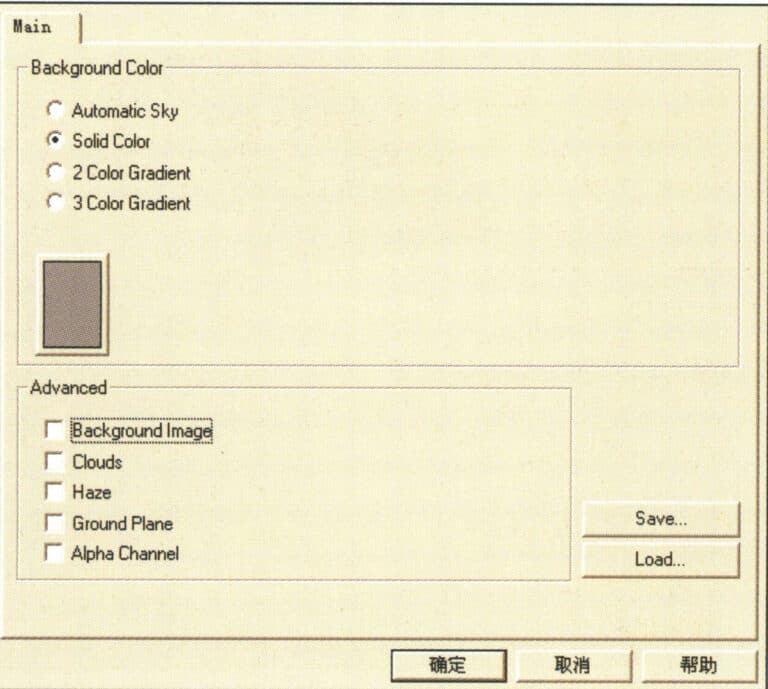
Environment options
(8) Advanced Options
Background Image — Set the image to the scene as the background image.
Clouds: Set the scene with cloud effects.
Haze – Set the scene with a smoke effect.
Ground Plane – Set the scene horizon.
(9) Flamingo’s Material Library
First, select the object, then choose the menu Edit > Object Properties (or click the icon in the floating tool panel) to enter the material library dialog, and select the Material option:
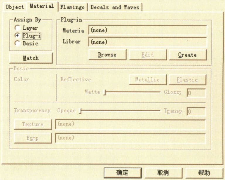
Object Properties dialog box
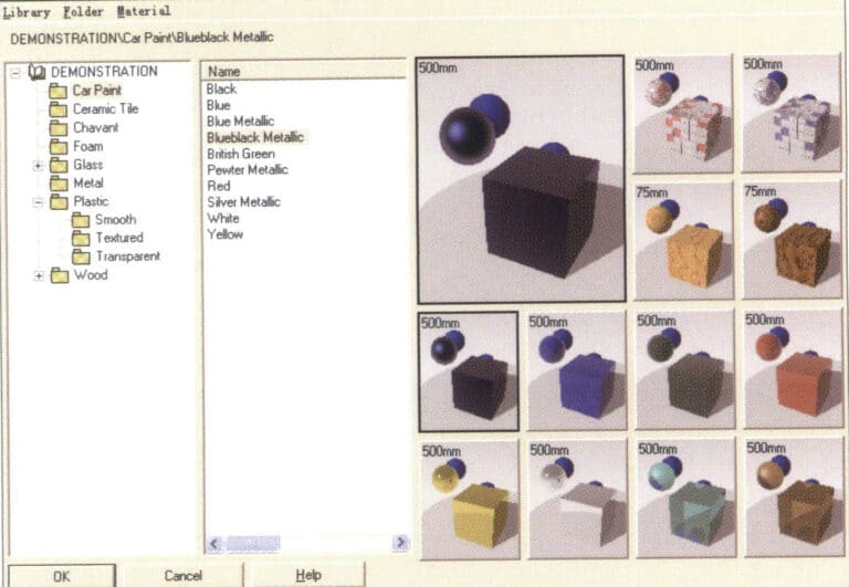
Material Library Dialog Box
The Flamingo renderer provides us with various material options, and the dropdown menu under Demonstration displays various material names. After entering the material name, the material effect appears on the right. Select the corresponding material name and click the OK button to add material properties to the selected object.
After assigning a material to the object, you can click the Edit button to enter the Flamingo Editor material dialog, which provides color settings, reflection and refraction value settings, object texture lighting properties, etc. You can adjust these as needed before confirming.
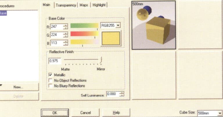
Material Editor Dialog Box
3. Learning TechGems

TechGems main module icon
TechGems
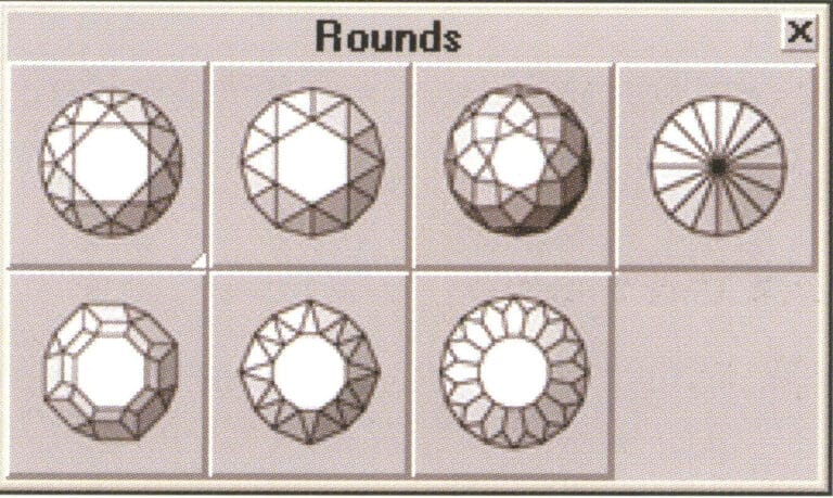
TechGems various round gemstone models
Round diamond model icon
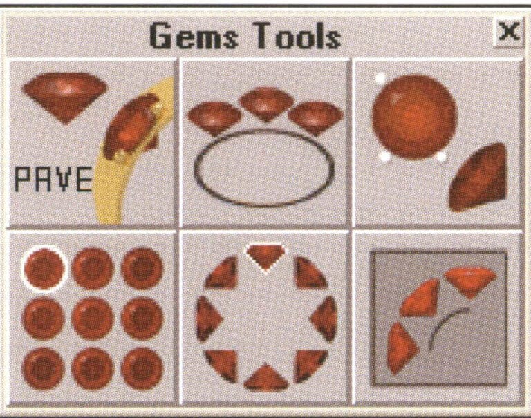
TechGems comes with six tool editing commands.
Gem Tool Icons
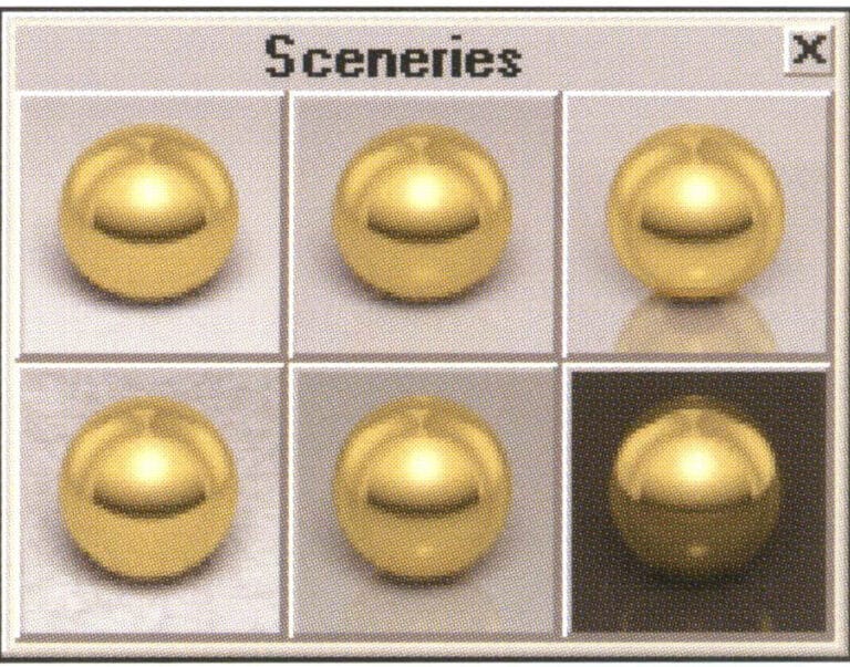
TechGems 1.1 provides six scene options.
Adjustable scene file icon
4. Rendering Jewelry Design Effects Using the Rhino Platform in Conjunction with Flamingo and TechGems
This chapter will provide a detailed step-by-step example to help readers understand how to create jewelry renderings using the Rhino platform with the Flamingo renderer and the TechGems plugin.
Open the Rhino system and open the RIO.3dm file to see the combined model of the ring. The design and modeling process is not described in this chapter, so let’s enter the world of rendering together.
Select the menu Render > Render command (or click the icon) in the floating tool panel) to pop up the rendering window. Without assigning any material to the object, the Rhino system provides a default plaster material, which, although the image quality is generally low, renders very quickly.

Object view
4.1 Endowing Objects with Metallic Texture
First, select one of the ring surfaces in the previous page’s image, then choose the command Edit > Object Properties from the menu (or click the icon in the floating tool panel to bring up the Properties dialog box).
Click the Browse button in the Plug-in section to enter the Material Library dialog box.
Expand the materials in the material library (You must install the TechGems plug-in before this material can appear. Select the Metals material category and continue to select Gold, Red Polished metal material; the material image style will appear on the right; click OK to confirm and close the dialog box.
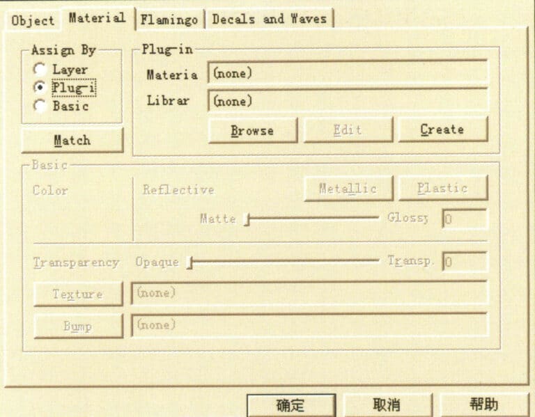
Enter Material Library
Choose other ring surfaces and apply different metal materials similarly, giving the gemstones the corresponding materials.
After material allocation, testing rendering can be performed. Click the render button to render.
The plaster material of the object itself is replaced by a metallic texture, resulting in changes in reflection and gloss on the metal surface. However, we see a large area of gray in the background of the painting because we have not yet added the scene settings.
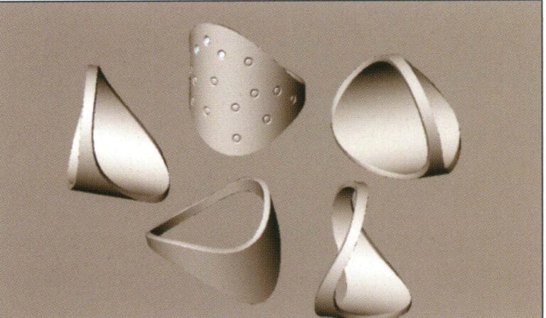
Rhino test rendering
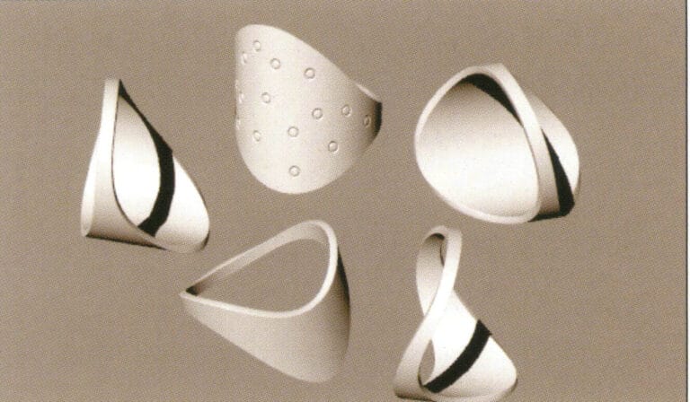
Flamingo test rendering
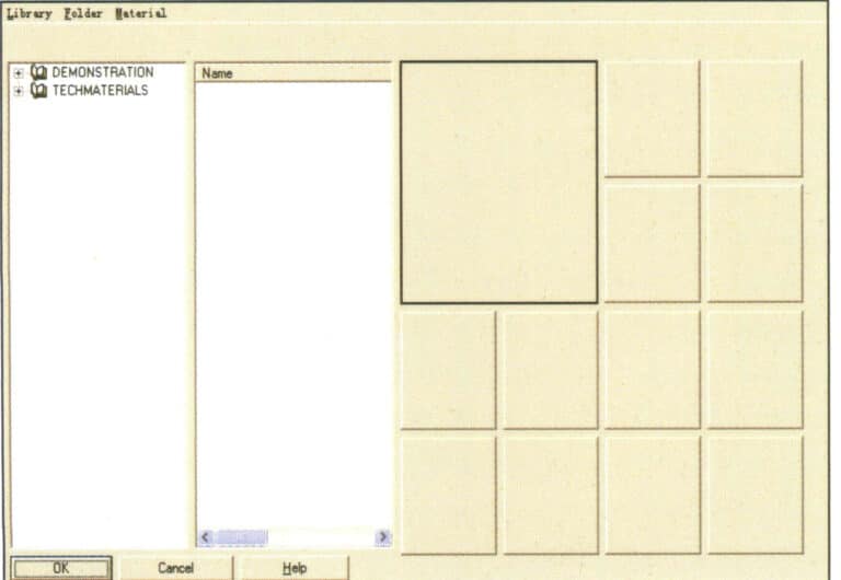
Material Library
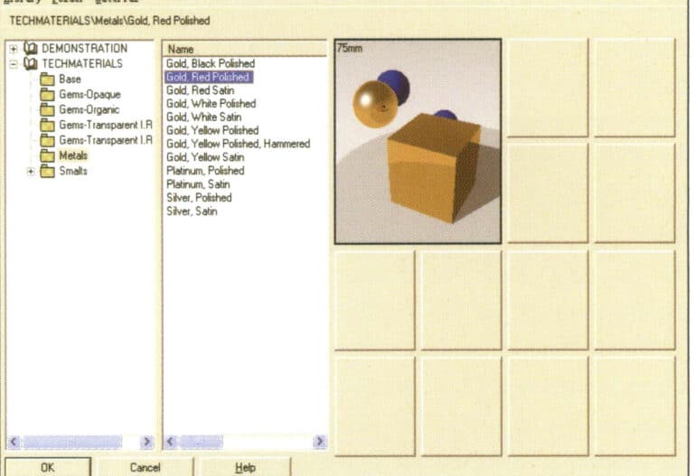
Choose the appropriate material
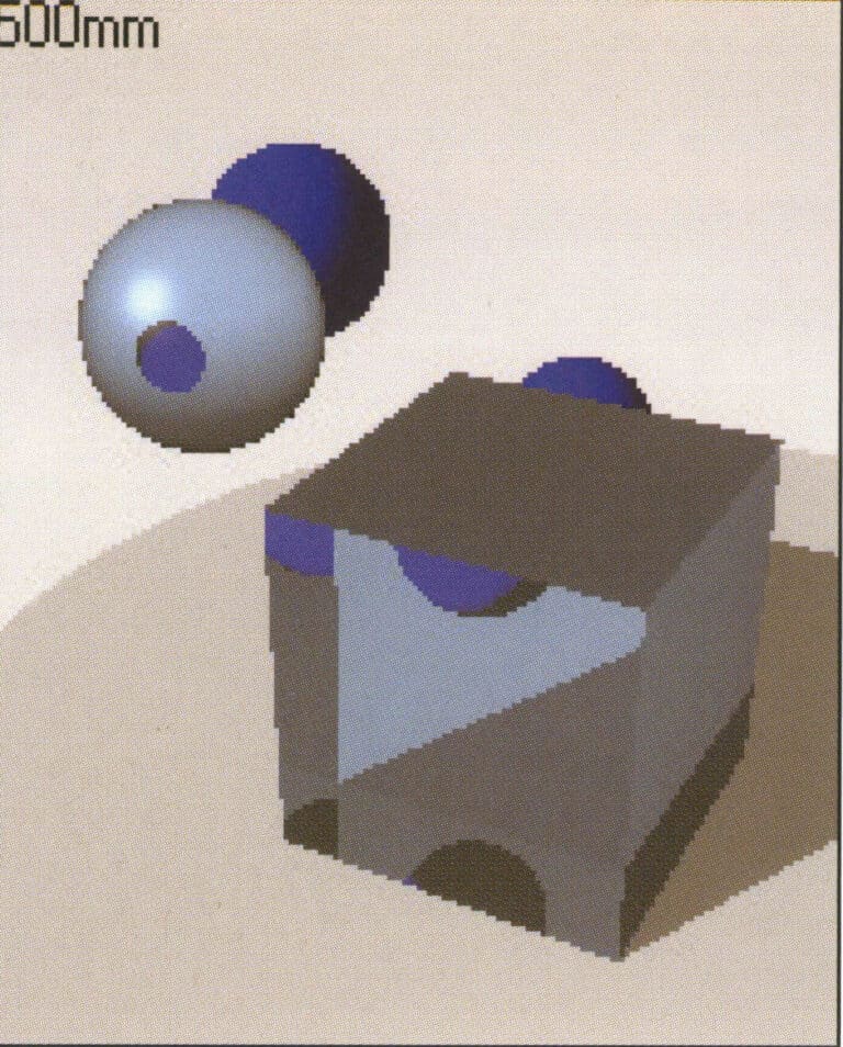
Gemstone material style
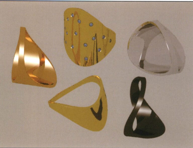
Test rendering
4.2 Setting the Scene
Select the Scenery Black Reflexive icon to import scene in the TechGems module.
The scene files provided by TechGems have already set up the corresponding scene models and lighting, and the material properties have also been configured. We need to adjust the camera angle to modify the rendering image and render again to obtain the effect.
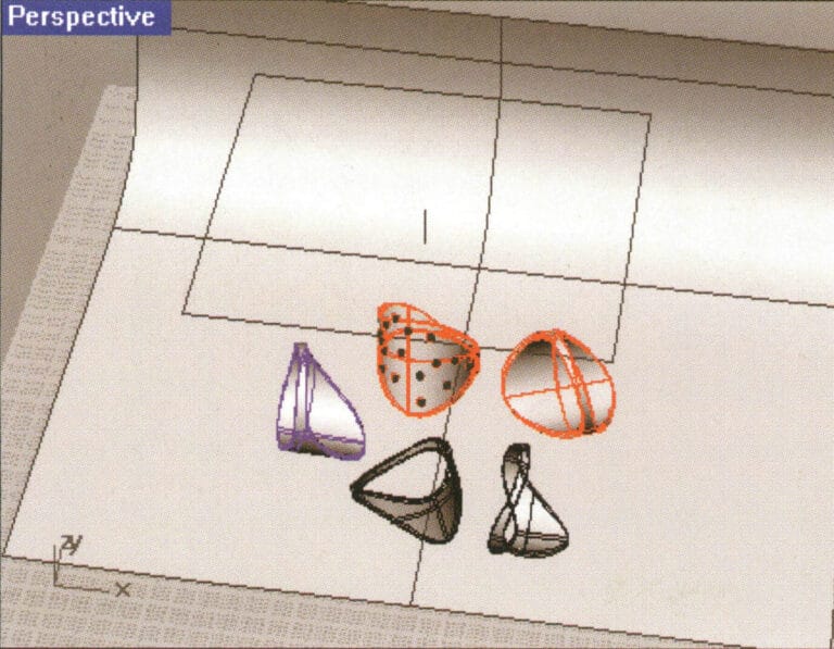
Test rendering

Test rendering
4.3 Environmental Setup
Adding environmental settings can make the surface colors and variations of the objects richer and more layered, presenting a more realistic scene.
Enter the Environment settings of the Flamingo parameter settings in the attribute editor, select 3 Color Gradient, and adjust.
Click rendering to enrich the metallic surface of the object with light and shadow, making the changes in brightness and darkness layered; however, the object’s shadow is too strong, and the transparency of the gem has not yet been displayed, requiring further adjustment of the settings.
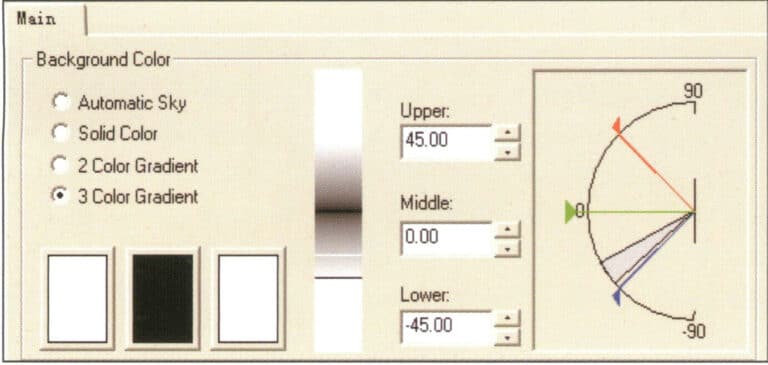
Environmental color change settings
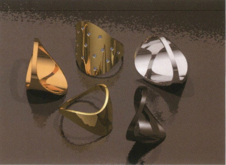
Test rendering
4.4 Adjusting the Bounces Settings
Set reflection to 12; this setting can increase the reflection value of transparent materials, making the object glossy, brighter, and richer in layers when reflecting.
Set the Transparency bounce value to 12. The larger the bounce value, the more times light refracts and reflects inside the object, resulting in richer color variations in transparent objects, thus achieving a more translucent effect.
Clicking render again, the shadows of the objects in the image are noticeably softened, making them more realistic; the color variations of the gemstones are evident, appearing more transparent; finally, after adjusting the antialiasing settings of the image, the work is complete.
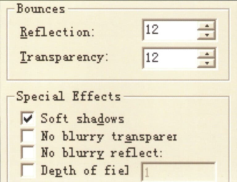
Setting Reflection and Bounce Values
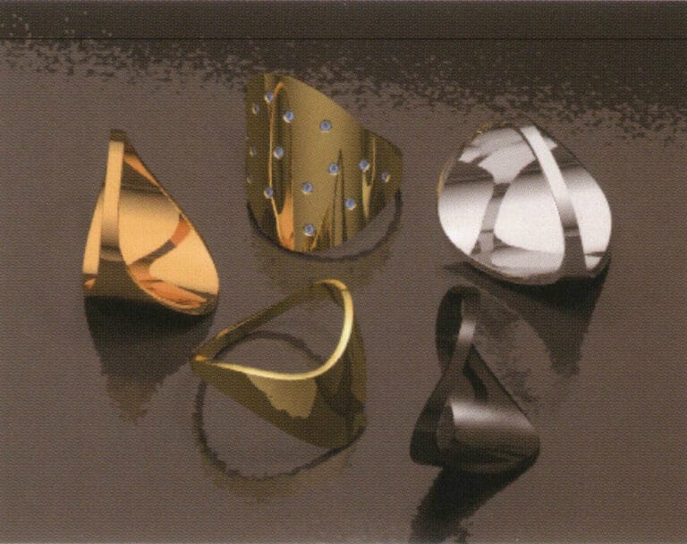
Test rendering
4.5 Setting the Antialiasing Capability and Detail Level of the Image
We also need to adjust the corresponding parameter settings during the final rendering. To improve the rendering quality of the image, select High > 16x (slow) in the Antialiasing options for high antialiasing capability. At this point, the rendered image’s objects, shadows, reflections, and other details will not have jagged edges, but choosing this setting will significantly extend the rendering time.
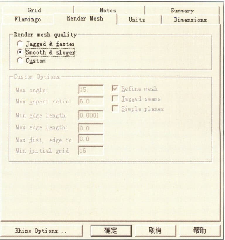
Open the Render Mesh option to set the rendering detail level, and select Smooth & slower in the Render Mesh quality section. This setting produces a more delicate image. The system also provides Custom manual parameter settings, extending the rendering time.
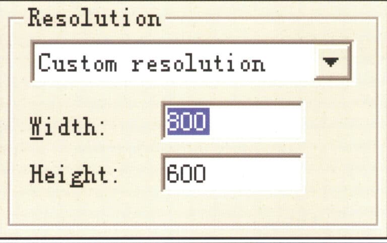
Finally, you can appropriately change the rendering size (adjust the corresponding height and width according to the actual aspect ratio of the image). After setting all the parameter data, you can proceed with the final rendering to obtain the final rendered effect image.
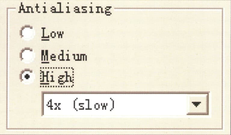
Set the antialiasing capability of the image
Set rendering size
Set the smoothness parameters for the image
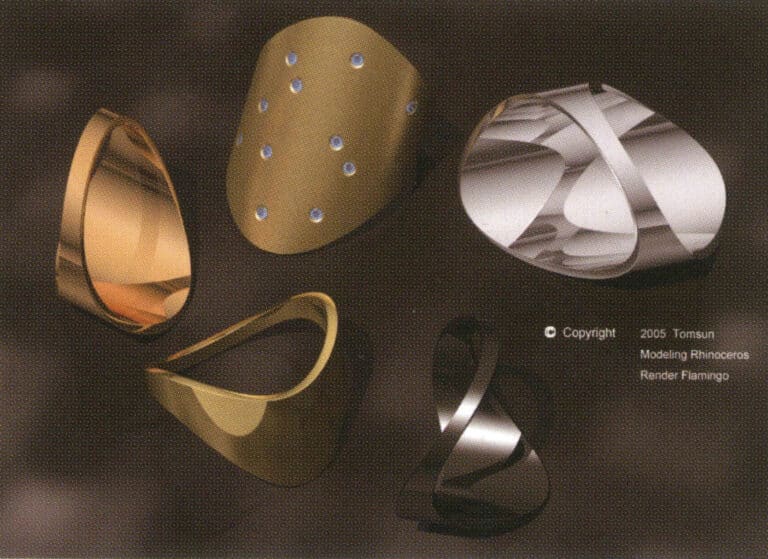
최종 렌더링
카피라이팅 @ 소블링.쥬얼리 - Sobling. 맞춤형 주얼리 제조업체, OEM 및 ODM 주얼리 공장
5. Creating Jewelry Design Renderings with Rhino
5.1 Pendant
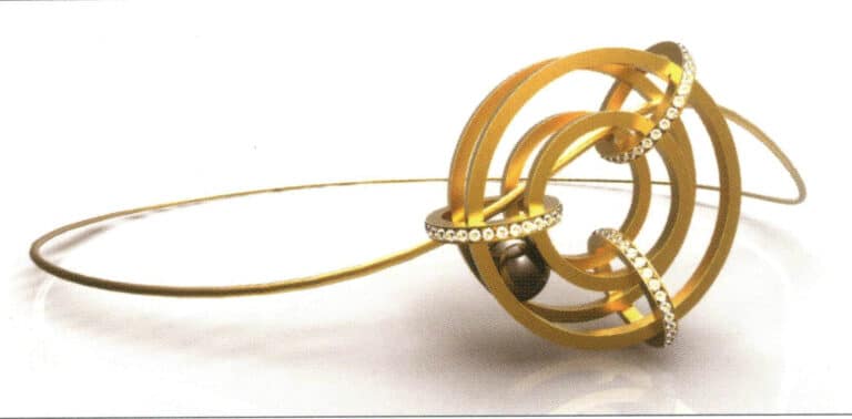
제작 단계는 다음과 같습니다:
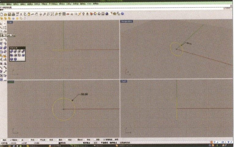
1. Open Rhino, select "Circle Tool," and draw a circular curve with a diameter of 6 mm on the Front plane

2. Select the curve that needs to be offset, long press "Curve Round Corner," then select "Offset Curve," input the required offset distance using the numeric keypad, press the stone key, and confirm.
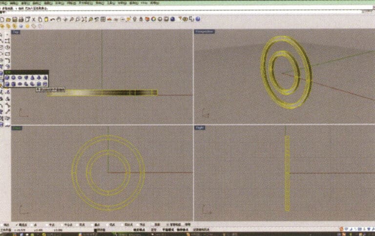
3. Select the four offset curves, long press , and choose "Solid Extrude," input the extrusion height using the numeric keypad and confirm, resulting in two ring-shaped solids
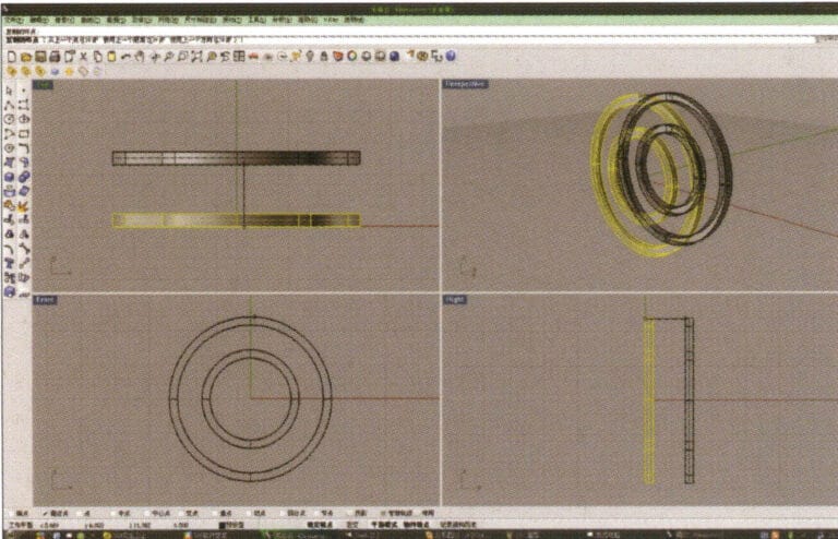
4. Select the two rings extruded in step 3, select “Duplicate”, enter the distance after duplication and confirm.
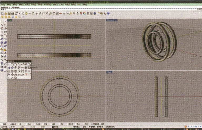
5. Select the circular curve with the largest diameter and use the "Offset Tool" to offset it to the middle of the upper and lower ring solids as a track
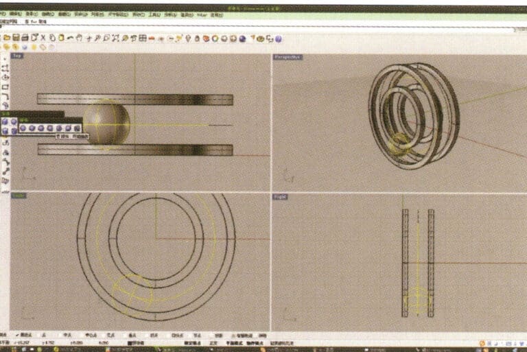
6. Select the curve as the trajectory, long press , and then long press to select "sphere, surrounding curve," check the capture command at the bottom of the window, then move the mouse to the desired drawing location, click the left button to confirm the position of the center, and then enter the radius of the sphere. After confirmation, the sphere is obtained
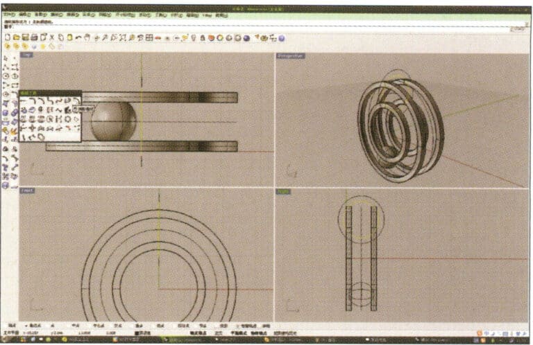
7. Similar to step 6, select the trajectory curve, long press , and choose "ring curve." Move the mouse to the center of the circle and enter the radius as prompted in the prompt bar to obtain the first ring curve, then select "offset" to get the second curve
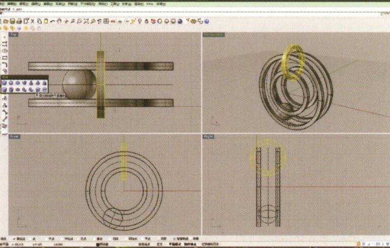
8. Select the two circular curves obtained in step 7, long press , and choose "Extrude," input the extrusion height using the numeric keypad and confirm while moving the circular solid to the center
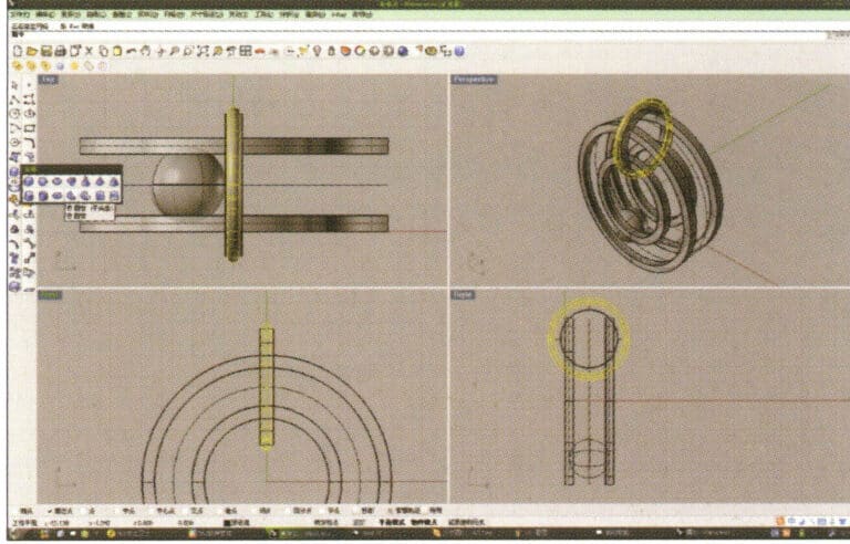
9. Select the previously created outer circular curve as the track, and choose tube to create a circular tube
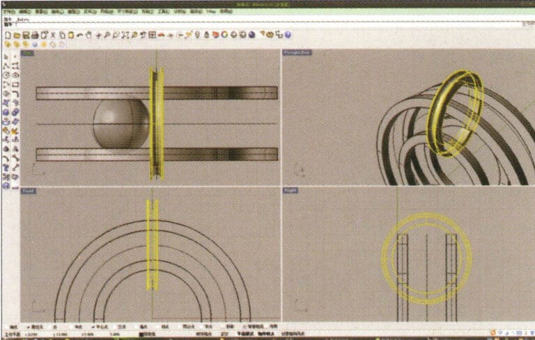
10. First select the ring-shaped solid, then choose "Boolean operation difference," and then select the circular tube and confirm
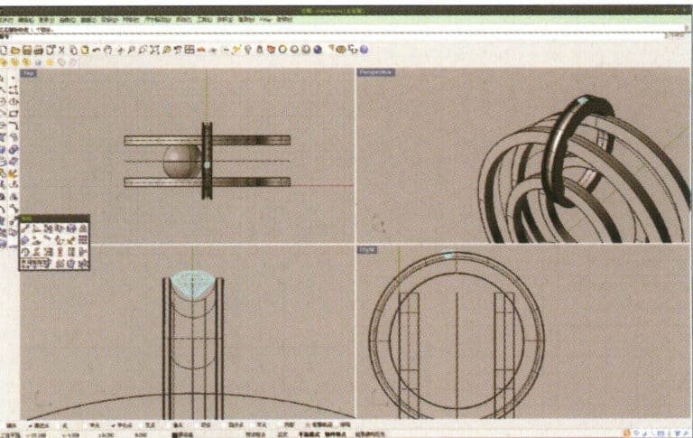
11. Import the diamond model and move it directly above the groove created in step 10
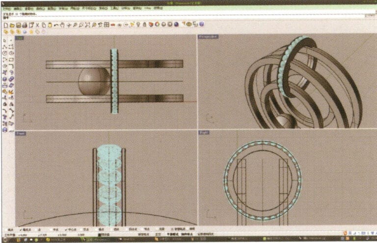
12. Select the diamond, long press , and choose "Circular Array," then follow the instructions in the prompt bar at the top of the window to enter the number of arrays and confirm
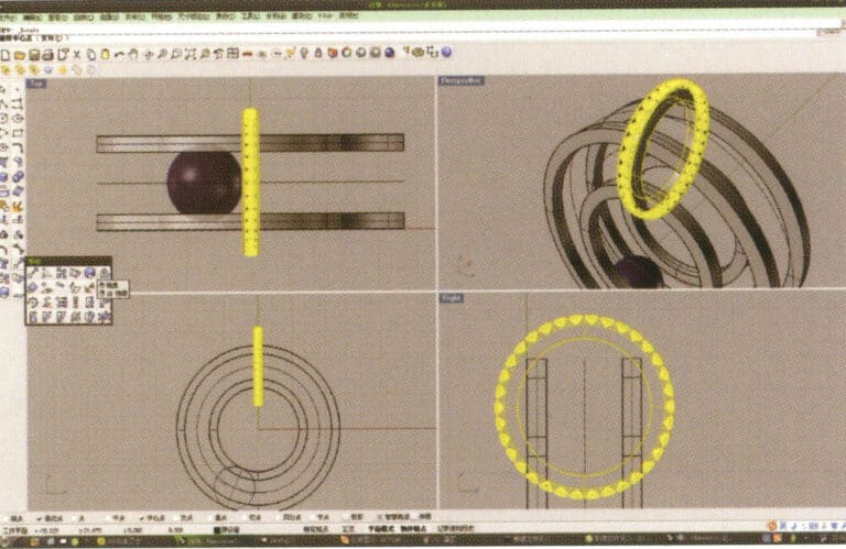
13. Select the annular surface and diamond obtained in step 12, and long press

14. Select "Mirror" for the chives, check the "Capture Command - Center Point" at the bottom of the window, and after determining the center point, perform the mirror operation using that center point
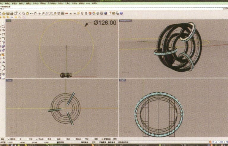
15. Select "Circle Tool" and draw a circular curve with a diameter of 126 mm on the Top plane
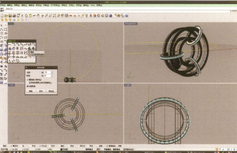
16. Select the curve obtained in step 14, choose "Rebuild," enter 10 in "Point Count," enter 5 in "Degree," and confirm
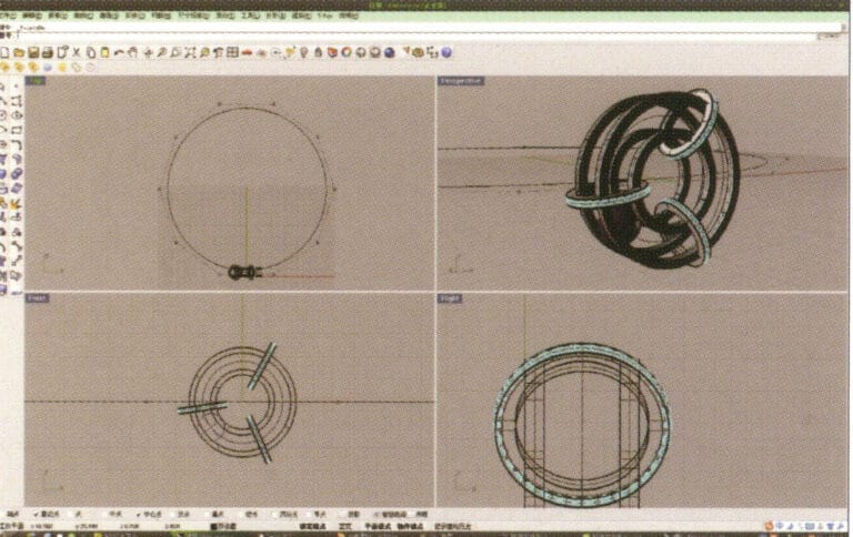
17. After confirmation, select the curve and press "F10" to display the 10 control points created earlier
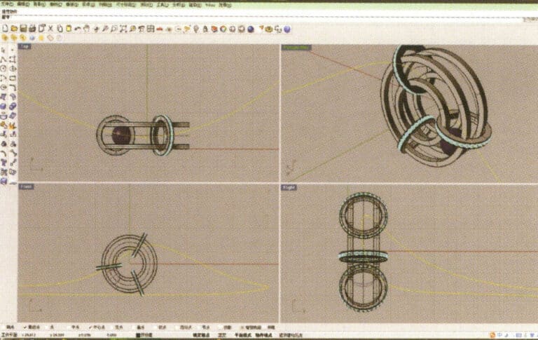
18. By selecting and moving control points, deform the curve and make it pass through the two small rings
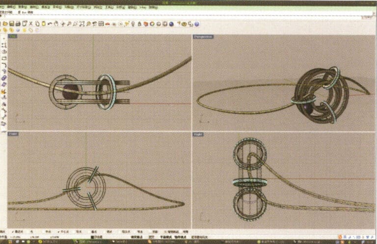
19. Choose the deformed curve as the track, and select "circular tube" to create a radius of 0.5 round tube
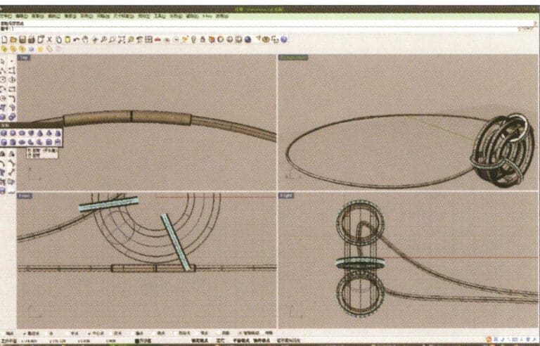
20. Use the same method as in step 18 to add details to the chain
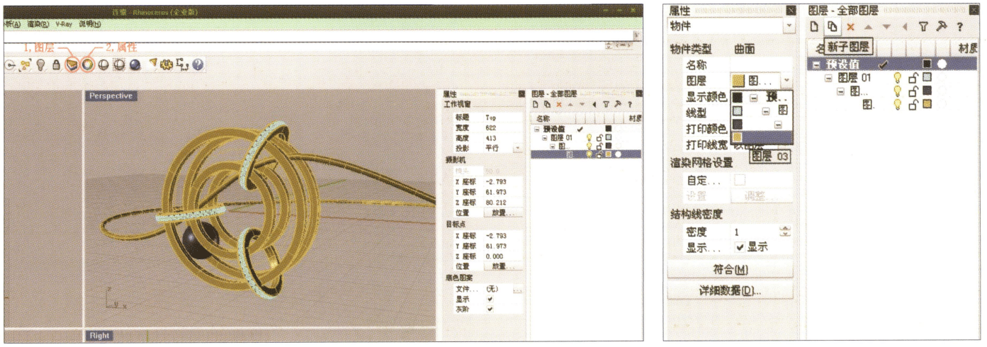
21. Select separately, first create a new layer in the "Layers" window on the right, then select the parts with the same material in the model, choose color layering in the "Layers" section of the "Properties" window, complete and save
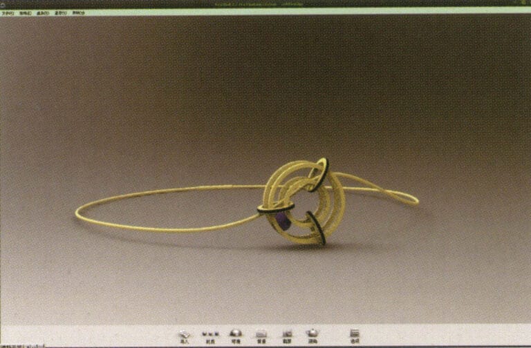
22. Select "rendering software" for rendering, and after opening, directly drag the "Rhino model" into the Keyshot workspace
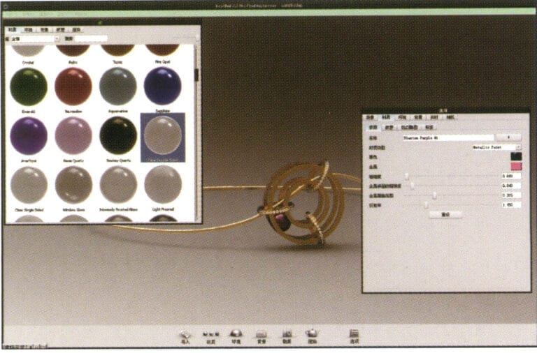
23. Open the "Material" library, select the desired material, and drag it directly onto the corresponding model part to start applying it. After completion, you can double-click the model to adjust the details of that part's material
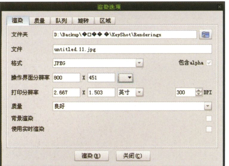
24. After adjusting the material, environment, and view, you can select "Render" to adjust the rendering quality
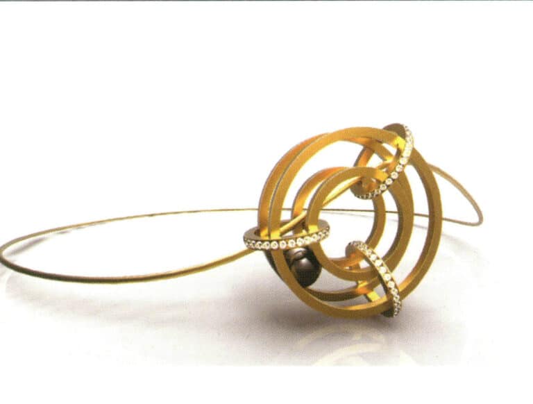
25. Rendering completed
5.2 Bracelet
제작 단계는 다음과 같습니다:
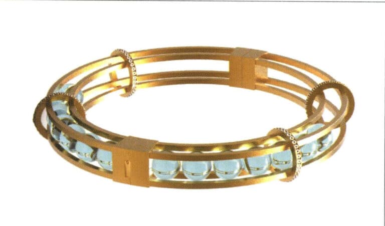
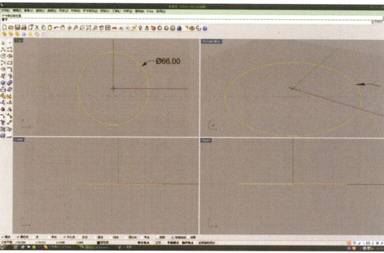
1. Open Rhino, select the "Circle Tool" and draw a circular curve with a diameter of 66 mm on the Top plane
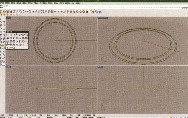
2. Select the curve that needs to be offset, long press "Curve Round Corner," then select "Offset Curve," input the required offset distance using the small keyboard, right-click, and confirm that the yellow curve in the image serves as the trajectory for the subsequent array of spheres
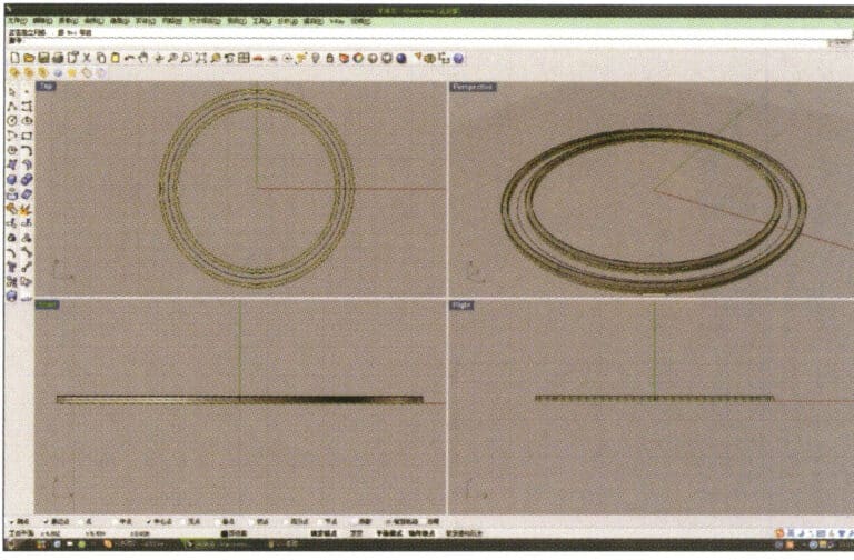
3. Select the two sets of curves to be extruded, long press and choose "Extrude," then enter the extrusion height using the numeric keypad and confirm

4. Select the two extruded surfaces from step 3, choose "Copy," enter the distance for the copy, and confirm; then select the curve used as the trajectory in step 2, and choose "Move" to move it up to the middle position between the two surfaces.
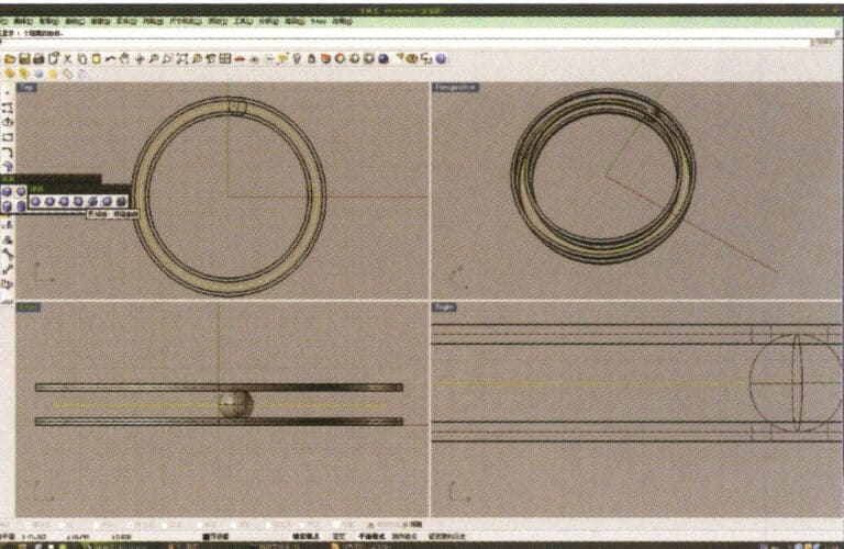
5. Select the curve as the trajectory, long press and then long press to select "sphere, surrounding curve," check the capture command "nearest point" below the window, then move the mouse to the location where you need to draw, click the left mouse button to confirm the position of the center of the sphere, then input the radius of the sphere, and after confirmation, obtain the sphere
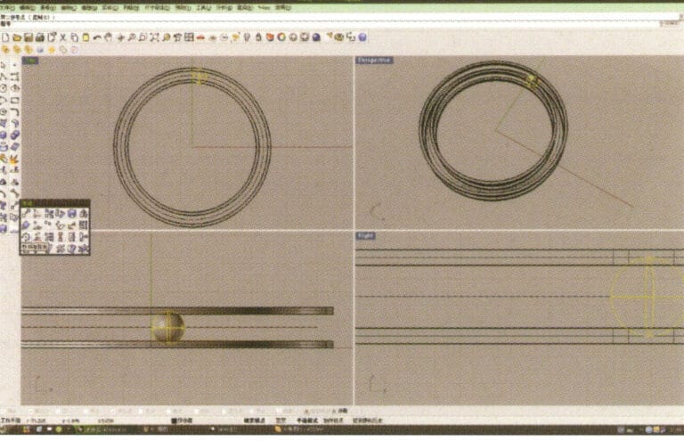
6. Select the sphere, long press and then select “Circular array”, and then follow the instructions in the prompt bar above the window, enter the number of arrays and confirm
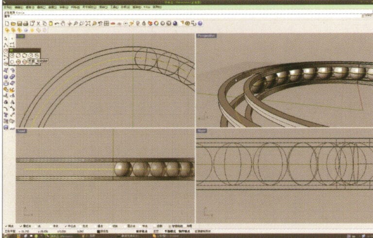
7. Similar to step 5, select the trajectory curve, long press , and then choose "ring curve." Move the mouse to the center of the circle and enter the radius as prompted in the prompt bar to obtain the first circular curve, then use "offset" to get the second curve
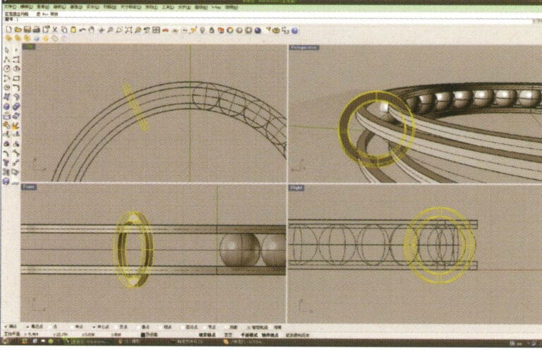
8. Select the two circular curves obtained in step 7, long press , and choose "Solid Extrude," enter the extrusion height using the numeric keypad and confirm
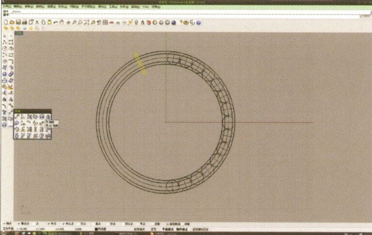
9. Select the annular surface obtained in step 8, long press then select "mirror."
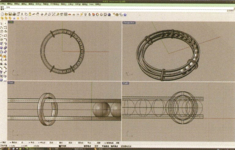
10. Check the capture command for the center point below the selection window, and after determining the center point, use it for the mirroring operation
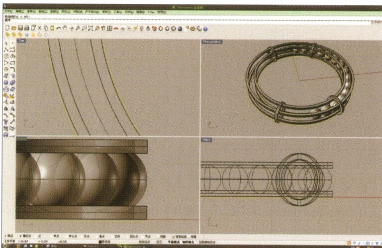
11. Select the outermost and innermost curves established initially and offset them one by one to obtain two new annular curves
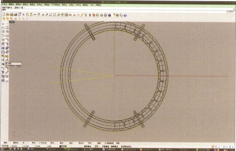
12. Create two straight lines, use "Split" to cut the two rings, and after completing that, use the resulting arcs to cut the two straight lines to obtain curves, then select and run to convert them into closed curves
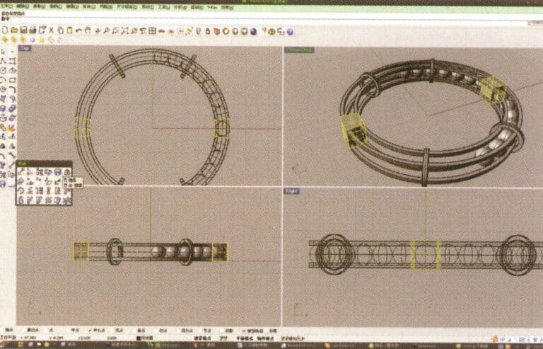
13. Select the closed curve obtained in step 12 and extrude it, then mirror it
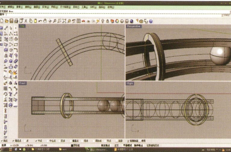
14. Select the edge curve of the circular solid, and choose "Offset Curve" to offset it to the center as the trajectory curve
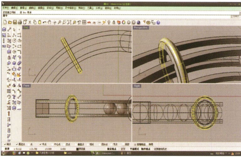
15. Long press to select "cylindrical tube," input the radius to obtain the cylindrical tube
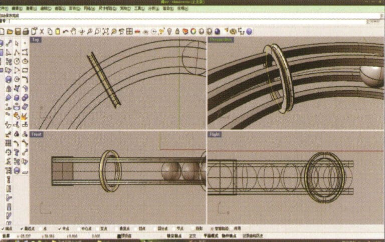
16. Select the small ring solid, long press to select "Boolean operation difference," then select the circular tube obtained in step 15, right-click and confirm (ring solid minus circular tube)
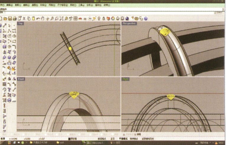
17. Import the diamond model and move it directly above the groove created in step 16
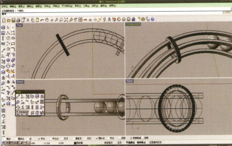
18. Select the diamond, then choose the "Circular Array Tool," and follow the prompts in the hint bar at the top of the window to input the number of arrays and confirm
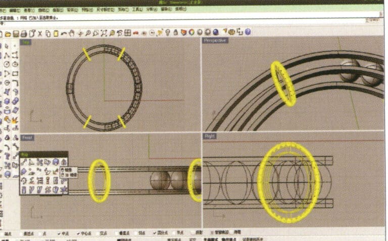
19. Hold down "Shift," select all the diamonds after the array, and use the "Mirror Tool" with the center point as the center to mirror the diamonds into the other three ring-shaped entities
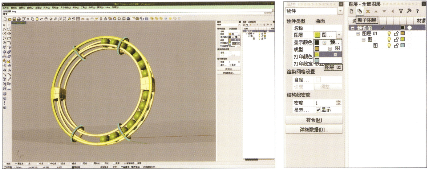
20. Select separately, first create a new layer in the "Layers" window on the right, then select the parts with the same material in the model, choose color layering in the "Layers" section of the "Properties" window, complete and save
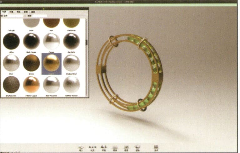
21. Select "rendering software" for rendering, and after opening, directly drag the "rhinoceros model" into the Keyshot workspace
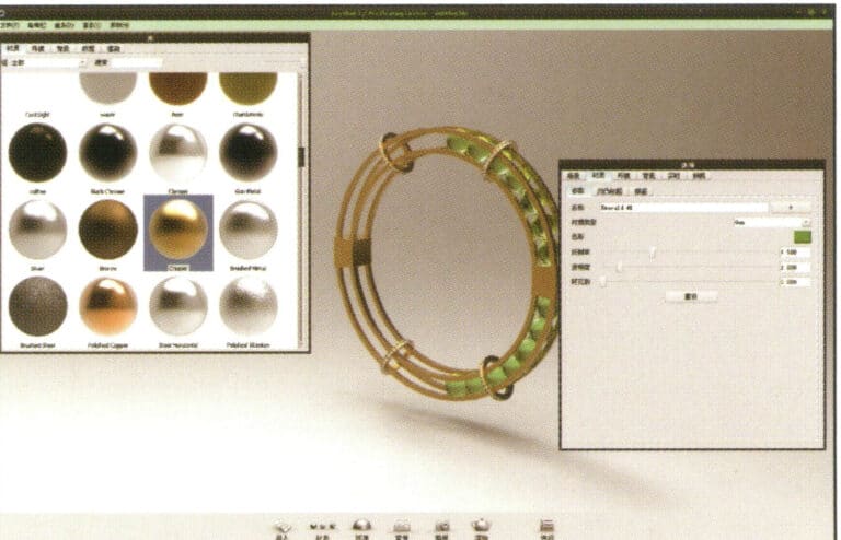
22. Open the "Material" library, select the desired material, and drag it directly onto the corresponding model part to start applying it. After completion, you can double-click the model to make detailed adjustments to that part's material
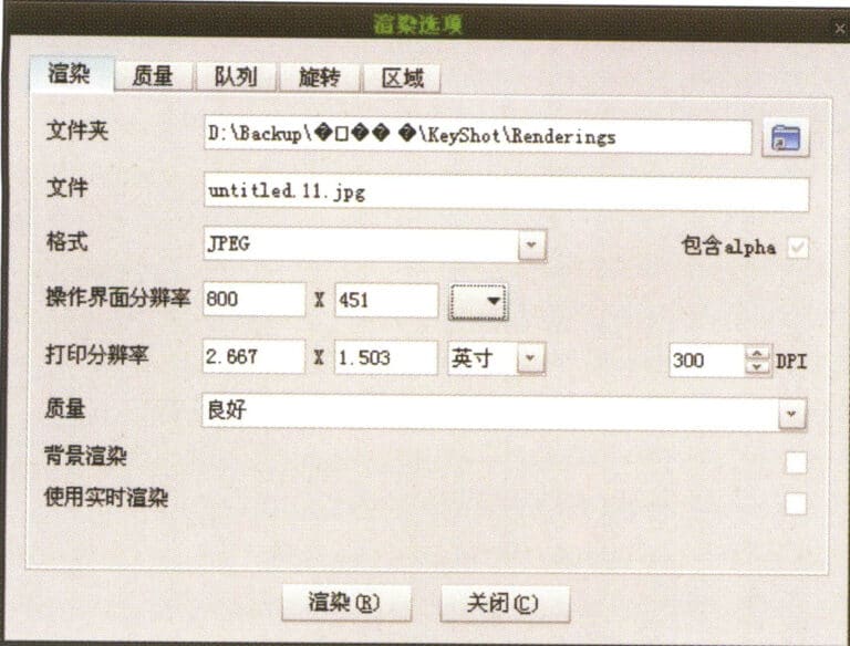
23. After adjusting the village quality, environment, and view, you can choose "render" to adjust the rendering quality

24. Rendering completed
Section II Aesthetic Review of Digital Paintings
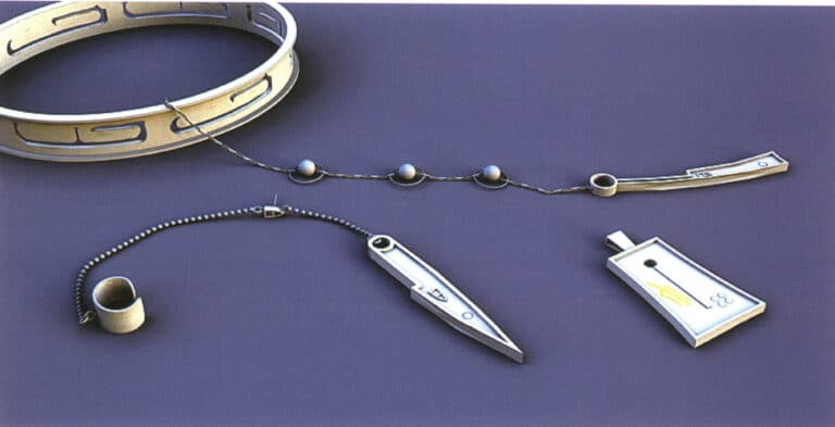
Modeling: Rhino; Rendering: 3ds max; The scene applied HDR textures to simulate real natural lighting and set up realistic sunlight; The image shows the object reflecting the red effect of real sunlight
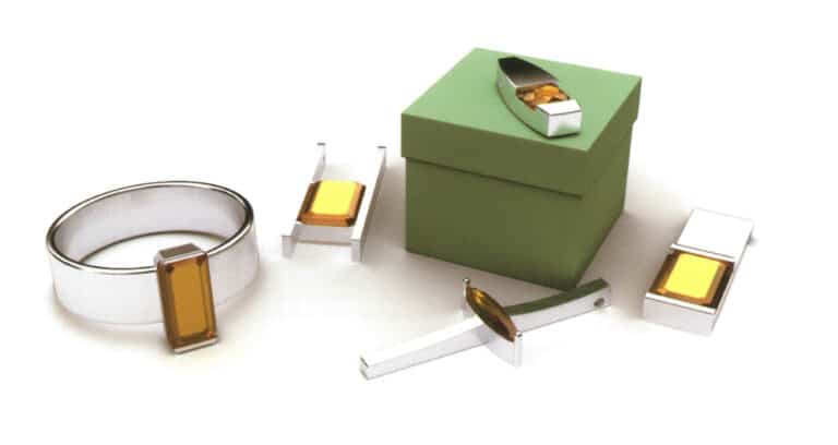
Modeling: Rhino; Rendering: 3ds max; The image simulates the effect of natural lighting, setting up the skylight, as if on open ground, influenced only by the environment of the ground and the effect of the skylight
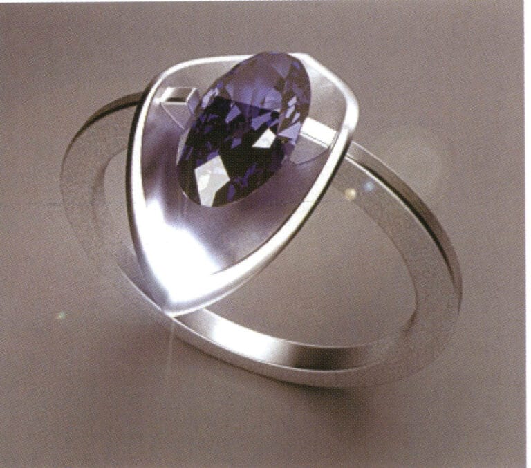
Modeling: Rhino; Rendering: 3ds max; The scene uses only one high-intensity surface light source, and the texture of the gemstones is presented quite ideally; due to the high-intensity reflection of the metal surface, the coarse particles on the ground are also reflected on the metal surface
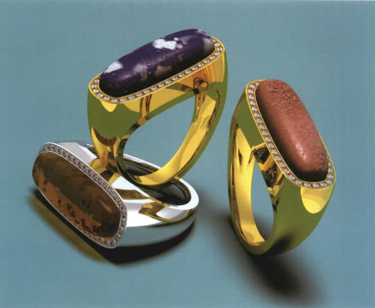
Modeling: Rhino; Rendering: Flamingo; Rich organic village textures (amber, coral, lapis lazuli)
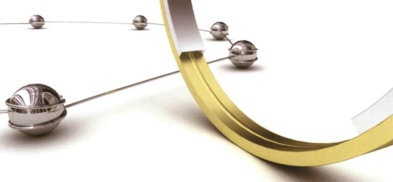
Modeling: Rhino; Rendering: 3ds max; Simulating natural daylight and adding depth of field effects to mimic the perspective visual effects in real life; The implementation of depth of field relatively extended the rendering time
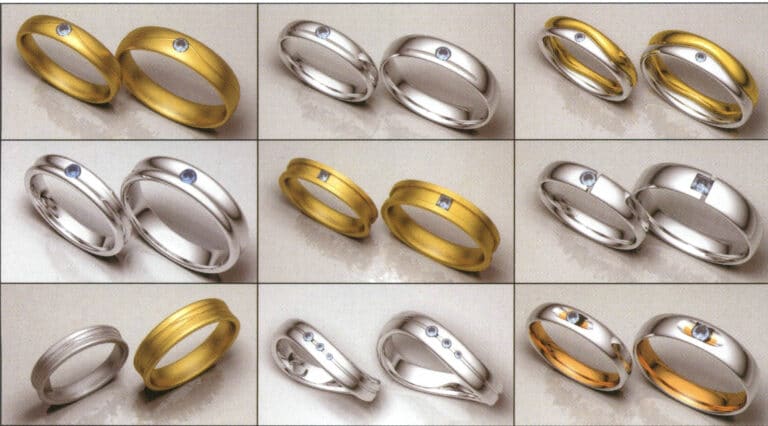
Modeling: Rhino; Rendering: Flamingo; Rendering of the wedding ring, different colored metal materials, special matte effect, observing the changes in light absorption and environmental reflection on the metal surface
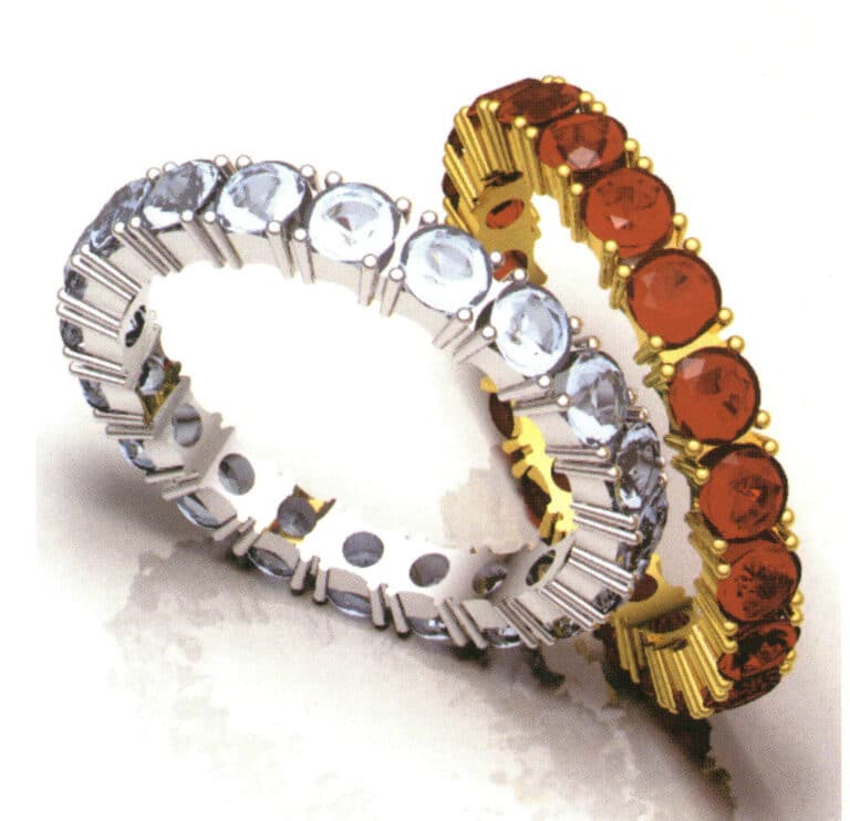
Modeling: Rhino; Rendering: Flamingo; Reasonably matches materials and renders the corresponding effects; Has the transparency effect of gemstone material

Modeling: Rhino; Rendering: Flamingo; The higher the quality of the NURBS surface of the object, the finer the image. Every detail must be strictly controlled during the modeling process.
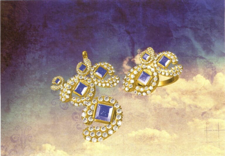
Modeling: JewelCAD; Post-processing: Photoshop; During the modeling process, pay attention to the angles and gaps between the repeated arrangement of components and enhance the texture of the metal and gemstones in post-processing
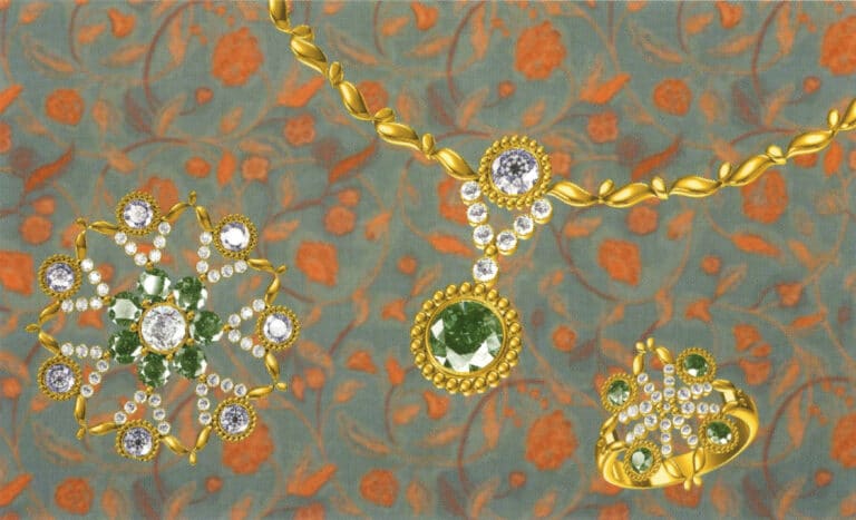
Modeling: JewelCAD; Post-processing: Photoshop; During the modeling process, attention should be paid to the variation in the curvature of cluster-set diamonds to ensure it is consistent with the curvature of the gemstones, as well as the connection between the metal parts of different setting methods
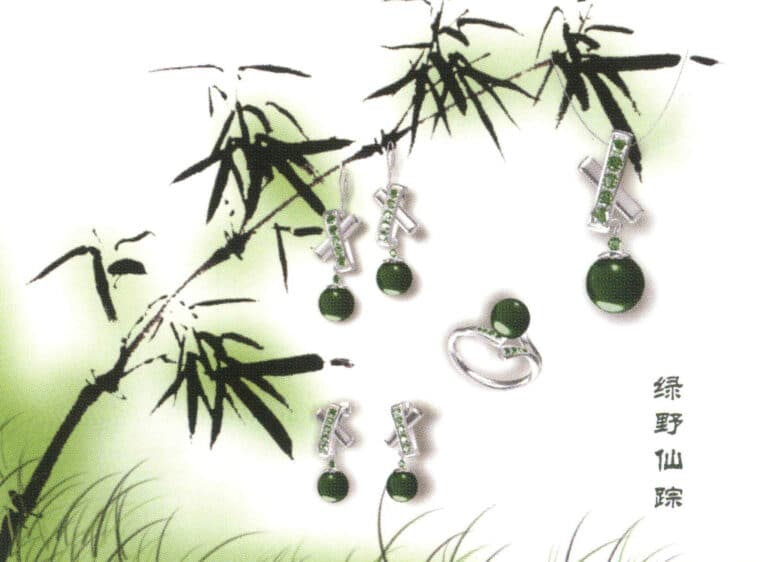
Modeling: JewelCAD; Post-processing: Photoshop. In the modeling process, we have to take into account the matching between the metal material and the gemstone material so that the whole design work has a better visual effect.
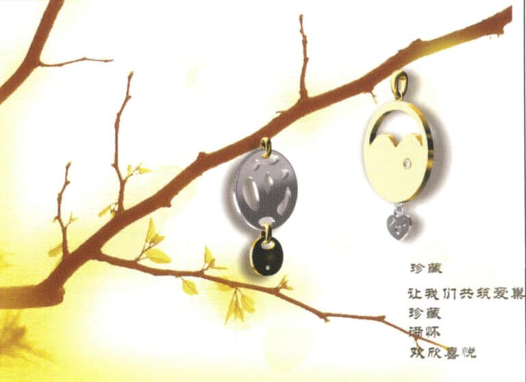
Modeling: JewelCAD; Post-processing: Photoshop; Pay attention to the change of light and shadow of the metal material, which can help to better express the sense of volume of the jewelry.
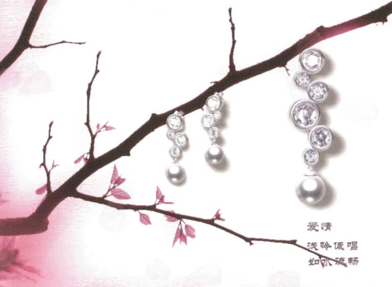
Modeling: JewelCAD; Post-processing: Photoshop; For more layers of jewelry, pay attention to the connection between the parts in the modeling process, which must be strictly in accordance with the structure of the jewelry to complete the metal part of the processing should pay attention to the changes in light and shadow
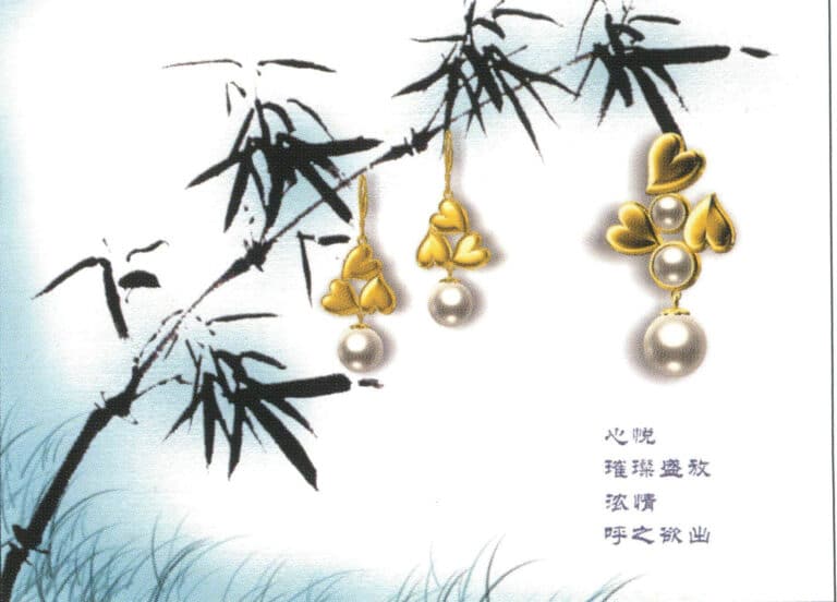
Modeling: JewelCAD; Post-processing: Photoshop; Selection of gemstone materials need to take into account the final modeling effect, pay attention to the contrast between light and dark metal and gemstone relations

Modeling: JewelCAD; Post-processing: Photoshop; For the representation of different metals, to fully reflect the color and texture differences of the metal
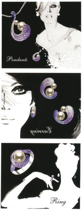
Modeling: JewelCAD; Post-processing: Photoshop. During the modeling process, attention should be paid to the fullness of the shape, and the combination of different colored gemstones should be applied to present a rich color effect.
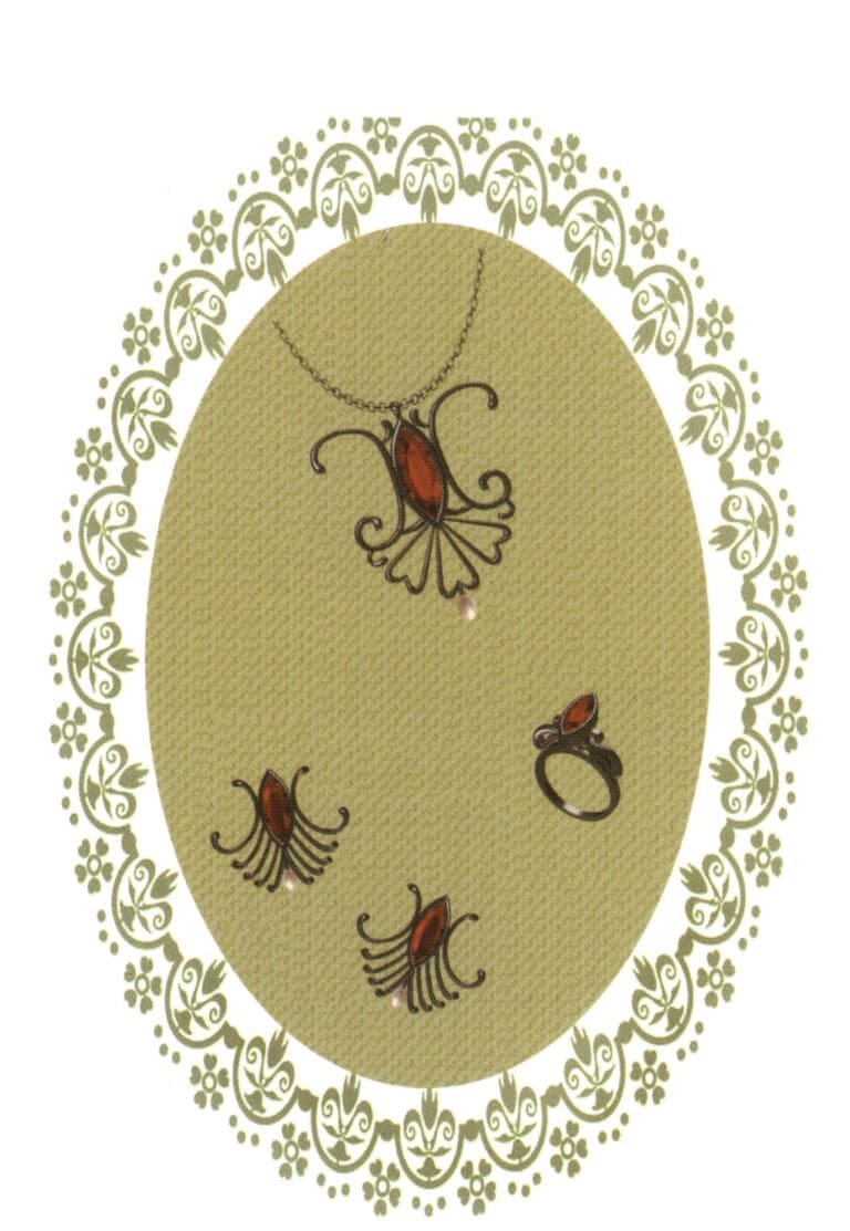
Modeling: JewelCAD; Post-processing: Photoshop; During the modeling process, pay attention to the smoothness of the guide rails and the connection of different section profiles, making the design work natural and comfortable


