


Bagaimana Cara Membuat Model Lilin Perhiasan dan Model Utama untuk Pengecoran Perhiasan?
Prinsip-prinsip dasar dan keterampilan operasional untuk 5 tugas umum
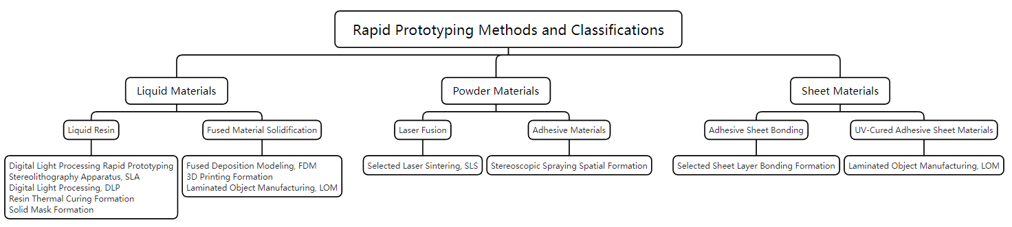
Dalam produksi perhiasan, pengecoran lilin yang hilang adalah proses pembentukan utama. Produksi model orisinal adalah langkah pertama dalam proses pengecoran, yang memiliki dampak signifikan terhadap kualitas pengecoran, efisiensi produksi, dan aspek lainnya. Metode tradisional produksi model asli terutama melibatkan model lilin ukiran tangan. Model lilin ukiran tangan adalah teknik pemodelan yang mengintegrasikan metode aditif dan subtraktif. Dengan mengacu pada gambar desain perhiasan, lilin digunakan sebagai bahan, dan alat pahat adalah media untuk memahat lilin ke dalam templat lilin yang sesuai dengan gambar desain. Teknik ini memungkinkan untuk membentuk model aslinya secara bebas. Namun demikian, karena ketergantungannya pada tenaga kerja manual, efisiensi produksinya rendah, dan stabilitas kualitas produk sulit dijamin. Dengan perkembangan teknologi, produksi model asli terutama mengandalkan teknologi pembentukan pencetakan 3D. Pencetakan 3D, yang secara akademis dikenal sebagai manufaktur aditif, mengacu pada pembuatan model tiga dimensi dengan mengiris model dan menumpuknya lapis demi lapis dengan peralatan, yang pada akhirnya menghasilkan model entitas tiga dimensi yang sepenuhnya konsisten dengan model data yang sesuai. Penerapan teknologi pencetakan 3D telah secara signifikan meningkatkan efisiensi produksi dan memastikan keakuratan dimensi produk. Tergantung pada bentuk bahan baku, metode penumpukan lapis demi lapis dalam pencetakan 3D juga bervariasi, termasuk pemodelan yang diawetkan dengan sinar UV, pemodelan deposisi leburan, dan sintering laser selektif. Pemodelan UV-Cured dan pemodelan deposisi leburan adalah metode yang paling umum digunakan untuk produksi model asli perhiasan.
Setelah model asli selesai, sariawan harus dipasang. Sprue adalah saluran yang dicadangkan untuk aliran logam cair selama proses pengecoran, dan juga merupakan saluran untuk mengkompensasi penyusutan logam selama penyempurnaan pengecoran. Pengaturan sariawan yang benar adalah kondisi dasar untuk memastikan kualitas pengecoran, dan banyak cacat pada pengaturan sariawan yang tidak masuk akal secara langsung atau tidak langsung menyebabkan pengecoran. Saat mengatur sariawan, perlu untuk mengikuti beberapa prinsip dasar sambil juga mempertimbangkan struktur, bahan, ukuran, dan karakteristik lain dari produk perhiasan.

Mengisi cincin kosong
Daftar Isi
Bagian I Produksi Model Lilin Ukiran Tangan
1. Latar Belakang Pengetahuan
1.1 Sifat-sifat Bahan Lilin
Lilin adalah bahan dasar untuk membuat model asli perhiasan. Berbagai jenis lilin digunakan dalam industri perhiasan, tetapi hanya sedikit yang memiliki keseimbangan kekuatan dan ketangguhan yang sesuai untuk mengukir model lilin. Sebagian besar lilin terlalu rapuh atau terlalu lunak, sehingga sulit untuk diukir dengan metode konvensional. Kesesuaian lilin untuk model ukiran terutama dievaluasi dari lima aspek: kekerasan, kekuatan, ketangguhan, keseragaman, dan titik leleh.
Lilin yang digunakan untuk mengukir model harus memiliki kekerasan yang memadai supaya permukaannya tidak mudah rusak apabila terkena tekanan, sehingga memungkinkan pengukiran pola yang halus.
Karena ketebalan dinding perhiasan pada umumnya kecil, dan sebagian perhiasan memiliki ketebalan dinding kurang dari 0,3 mm, maka diperlukan lilin ukiran yang memiliki kekuatan dan ketangguhan yang memadai agar bahan lilin yang tipis tidak berubah bentuk atau pecah.
Bahan lilin juga harus memiliki kerapatan yang seragam. Untuk memastikan bahwa pola pada model lilin memiliki kejernihan yang sama, ketebalan dinding lilin harus konsisten. Apabila kerapatan bahan lilin seragam, metode untuk menilai ketebalan dinding biasanya cukup sederhana: lihatlah warna model lilin di berbagai tempat terhadap cahaya; jika ketebalan dinding tidak konsisten, warnanya akan berbeda. Namun demikian, apabila kerapatan bahan lilin tidak merata, meskipun ketebalan dindingnya sama, namun dapat menampilkan warna yang berbeda, yang dapat menyebabkan kesalahan penilaian selama pengoperasian.
Untuk model lilin yang secara langsung digunakan untuk pengecoran lilin yang hilang, bahan lilin juga diharuskan mudah meleleh selama proses pemanggangan, memiliki koefisien muai panas yang kecil, dan meninggalkan residu yang minimal setelah pemanggangan.
Merek lilin ukiran yang terkenal di industri ini termasuk Ferris, Matt, dan Kerr dan sebagainya.
1.2 Klasifikasi Bahan Lilin
Menurut performa dan karakteristik pemrosesan yang berbeda-beda, lilin ukiran dapat diklasifikasikan dalam berbagai cara.
(1) Klasifikasi berdasarkan Kekerasan
Menurut kekerasannya, lilin ukiran dapat dibagi ke dalam tiga kategori: lilin dengan kekerasan tinggi, lilin dengan kekerasan sedang, dan lilin lembut. Untuk memudahkan pembedaan, industri ini menggunakan warna yang sesuai. Hijau, ungu, dan biru digunakan untuk mewakilinya. Mengambil lilin ukiran merek Ferris sebagai contoh, karakteristik lilin hijau, lilin ungu, dan lilin biru adalah sebagai berikut.
Lilin hijau: Lilin ini memiliki kekerasan tertinggi dan elastisitas serta kelembutan terendah. Green wax adalah lilin ukiran yang paling banyak digunakan, cocok untuk mengukir sudut yang tajam dan detail yang rumit pada model lilin. Dapat diproses hingga ketebalan kurang dari 0,2 mm, mempertahankan bentuknya dengan baik tanpa mudah berubah bentuk, dan dipoles hingga mulus seperti kaca. Ketangguhan lilin hijau yang rendah membuatnya rentan terhadap keretakan apabila mengukir permukaan lengkung yang besar dan tipis. Suhu leleh lilin hijau adalah 110℃, dan ketika meleleh, lilin ini bisa langsung berubah menjadi cairan tanpa melalui tahap padat. Berbagai gergaji lilin, pisau ukir, kikir lilin, dan bur mesin dapat dengan mudah memotong, mengikir, dan memproses tekstur permukaan dengan lilin hijau.
Lilin ungu: Lilin ungu memiliki kekerasan sedang, elastisitas yang baik, dan kelembutan, sehingga cocok untuk membuat model lilin yang lebih rumit. Suhu leleh lilin ungu adalah 107℃, dan menjadi lebih lembut apabila dipanaskan, dan semakin lembut saat suhu meningkat hingga berubah menjadi cairan, sehingga tidak cocok untuk membuat pola yang halus.
Lilin biru: Lilin biru memiliki kekerasan paling rendah dan sangat lembut, sehingga cocok untuk membuat model lilin sederhana, khususnya untuk karya yang memiliki permukaan berbentuk bola atau lengkung. Sepotong lilin biru setebal 3 mm bisa dibengkokkan menjadi bentuk setengah bola setelah direndam dalam air mendidih. Lilin biru paling baik diukir dengan pisau, karena tidak menghasilkan serbuk lilin seperti lilin hijau atau luntur seperti lilin ungu. Lilin biru meleleh pada suhu 104℃ tetapi tidak berubah menjadi cairan yang mengalir; lilin ini mempertahankan kekentalan tertentu. Sangat nyaman menggunakan lilin biru untuk meniru pola permukaan model master, tetapi tidak cocok untuk membuat pola yang sangat halus atau memproses dengan penggiling gantung.
(2) Klasifikasi Berdasarkan Bentuk dan Penggunaan
Dari segi bentuk, bahan lilin bisa berupa balok, lembaran, tabung, strip, benang, dll. Berbagai bahan lilin yang sudah dibentuk sebelumnya atau aksesori lilin tersedia untuk dipilih, seperti lilin cincin, lilin gelang, lilin bezel, lilin cabang, dan lilin pembentuk tambahan lainnya untuk memudahkan penggunaan produksi, menghemat waktu pemrosesan, dan mengurangi kehilangan bahan lilin. Bentuk, karakteristik, dan kisaran aplikasi bahan lilin yang umum digunakan untuk ukiran tangan ditunjukkan pada Tabel 1-1.
Tabel 1-1 Bahan Lilin yang Umum Digunakan untuk Ukiran Tangan
| Kategori Bahan Lilin | Bentuk | Karakteristik | Rentang Aplikasi |
|---|---|---|---|
| Lilin Keras (Batu Bata Lilin, Lembaran Lilin, dll.) |

|
Kekerasan tinggi, kinerja pemrosesan yang sangat baik, sangat cocok untuk ukiran | Model lilin untuk mengukir perhiasan, ornamen, dan kerajinan tangan |
| Lilin lembut |

|
Kekerasan rendah, mudah ditekuk dan berubah bentuk, dapat dibentuk dengan bebas | Aksesori biomimetik dengan desain garis, seperti daun tanaman, tanaman merambat, dan tekstur sayap serangga |
| Lilin cincin |

|
Desain untuk cincin mencakup platform berbentuk bulat murni dan "U", dengan tipe solid dan berongga, sehingga menghemat waktu pemrosesan. | Membuat cincin pria dan cincin wanita |
| Lilin gelang |

|
Dapat digunakan untuk membuat gelang bulat, oval, dan persegi, menghemat waktu pemrosesan | Membuat gelang |
| Mengatur lilin |

|
Bentuk standar, ukuran dan kekuatan tinggi, tidak mudah patah | Model lilin untuk membuat bezel batu permata standar |
| Lilin cabang |

|
Ukuran lengkap, elastisitas bagus, bisa ditekuk lilin, tidak mudah patah | Membuat cabang dan bagian lilin pemodelan linier |
1.3 Terminologi Ukuran Struktur Model Lilin
Apabila personel pembuat model menerima pesanan, mereka harus terlebih dulu memahami persyaratan pelanggan berdasarkan pesanan, misalnya, ukuran perhiasan, ukuran batu permata, dll. Mengambil cincin sebagai contoh, perlu untuk memahami arti spesifik dari istilah-istilah berikut ini.
Ukuran cincin: Diameter bagian dalam cincin, yang dapat diukur dalam berbagai standar, seperti ukuran Amerika, Hong Kong, Jepang, dan Italia.
Lebar bawah cincin: Umumnya disebut dalam industri ini sebagai “lebar ring shank,” mengacu ke lebar di bagian paling bawah ring.
Ketebalan dasar cincin: Umumnya disebut sebagai “ketebalan ring shank” dalam industri, yang mengacu pada ketebalan di bagian paling bawah ring.
Tinggi cincin: Umumnya disebut sebagai “tinggi bahu” dalam industri ini, yang mengacu ke ketinggian vertikal tepi kepala ring.
Tinggi cabang: Umumnya disebut sebagai “tinggi sisi” dalam industri, ini mengacu pada tinggi total kepala, yang perlu diukur dengan kaliper.
Betis polos: Mengacu pada area antara tangkai cincin dan kepala, yang merupakan bagian yang tersisa setelah melepas batu pengatur paving atau pola lainnya.
Ketebalan betis polos: Mengacu pada ketebalan area di kedua sisi kepala tanpa posisi pengaturan pave, diukur dengan kaliper internal. Jika pelanggan tidak memiliki persyaratan khusus, biasanya diambil 0,6 ~ 0,7 mm.
Ketebalan pengaturan posisi pengaspalan: Mengacu pada ketebalan posisi pengaturan pengaspalan, yang perlu diukur dengan kaliper internal. Jika pelanggan tidak memiliki persyaratan khusus, maka dapat dianggap sebagai 1 ~ 1,2 mm.
Pengaturan ketebalan tepi dudukan batu: Mengacu ke ketebalan di sekeliling dudukan pengaturan kepala, yang bisa dianggap sebagai 1,1~1,3 mm.
Lokasi spesifik dari istilah-istilah di atas ditunjukkan pada Gambar 1 - 1.

Ukuran batu permata: Mengacu pada dimensi batu permata. Jika pesanan termasuk batu permata, posisi pengaturan dapat dibuka sesuai dengan ukuran sebenarnya; jika pesanan tidak termasuk batu, kisaran ukuran batu permata harus ditentukan berdasarkan kode informasi batu permata dalam pesanan. Gaya pemotongan batu permata umumnya meliputi potongan bulat brilian, potongan baguette, dan potongan putri, dll.
1.4 Koefisien Ekspansi Termal
2. Pelaksanaan Tugas
Tugas ini mengambil model lilin cincin emas murni sebagai contoh, terutama menggunakan pengerjaan relief dangkal untuk menyelesaikan produksi model lilin ukiran tangan.
(1) Memotong Bahan sesuai dengan Pesanan
Menurut spesifikasi dan dimensi pola, gunakan kaliper untuk mengukur dimensi dan menarik garis, dan gunakan gergaji besi untuk memotong blok lilin yang diperlukan, seperti ditunjukkan pada Gambar 1-2.
(2) Pembentukan Kasar
Letakkan blok lilin yang sudah dipotong pada kikir persegi untuk menghaluskannya, menciptakan tiga permukaan bersudut siku-siku, yaitu tampak depan dan tampak atas pada sudut siku-siku, tampak depan dan tampak samping (kiri atau kanan) pada sudut siku-siku, serta tampak atas dan tampak samping pada sudut siku-siku, seperti diperlihatkan pada Gambar 1-3. Setelah memoles tiga sudut siku-siku, gunakan kaliper untuk menggambar garis dasar yang berpotongan di tengah dan tegak lurus di sepanjang tepi sudut siku-siku (termasuk bagian atas dan belakang, yang disebut sebagai garis vertikal tengah) dan garis kontur pemasangan seperti yang ditunjukkan pada Gambar 1-4. Gunakan kompas dengan perpotongan garis kontur dudukan dan garis vertikal tengah sebagai titik awal, dengan setengah ukuran cincin sebagai jari-jarinya, untuk mengambil titik-titik pada garis vertikal tengah dan menggunakannya sebagai pusat untuk menggambar kurva melingkar bagian dalam cincin (termasuk bagian belakang), seperti yang ditunjukkan pada Gambar 1-5.

Gambar 1-2 Lilin Gergaji

Gambar 1-3 Mengarsipkan Blok Lilin

Gambar 1-4 Menggambar Garis Dasar

Gambar 1-5 Menggambar Garis Busur
Kemudian bor lubang kecil di sisi dalam busur, masukkan mata gergaji, dan gunakan bingkai gergaji untuk memotong lubang seukuran cincin di sepanjang garis busur, seperti yang ditunjukkan pada gambar 1-6.
Gunakan bur mesin lilin untuk memangkas tepi lingkaran bagian dalam, lalu gunakan pisau ukir cincin lilin untuk mengikis diameter lingkaran bagian dalam ke posisi pembacaan skala ukuran cincin, pastikan permukaan bawah dan atas lubang ukuran cincin memiliki ukuran yang sama seperti yang ditunjukkan pada Gambar 1-7.

Gambar 1-6 Menggergaji lubang seukuran cincin

Gambar 1-7 Mengikis ukuran cincin
(3) Perincian Halus
Setelah menyelesaikan bentuk keseluruhan, lanjutkan ke langkah berikutnya yaitu perbaikan detail. Gunakan bur mesin lilin untuk membentuk bentuk luar cincin, gunakan kikir persegi untuk membuat tepi kiri dan kanan simetris, dan ratakan tepi bawah, seperti yang ditunjukkan pada Gambar 1-8. Gunakan kaliper untuk menggambar garis tengah di sisi samping, atur lebar pemasangan dan tepi bawah, dan gunakan bur mesin lilin untuk membentuk kedua tepi. Jika cincin pria memiliki tepi lurus miring ganda, letakkan di atas kikir persegi untuk menggilingnya menjadi bentuk simetris diagonal. Berhati-hatilah untuk mempertahankan bentuk keseluruhan cincin, dan gunakan kikir lilin kecil untuk memperhalus bentuknya, pastikan keempat sisinya rapi dan simetris. Gunakan bur runcing untuk menggambar pola (huruf, bentuk, atau desain) pada pemasangan (permukaan cincin), dan gunakan pisau diagonal atau pisau bulan sabit berukuran sedang untuk mengukir garis tepi dalam, garis tepi luar, atau mengukir huruf secara berurutan, seperti yang ditunjukkan pada Gambar 1-9. Gunakan pisau samping untuk melubangi celah antara bingkai dan huruf (atau bentuk), dan kemudian gunakan pisau datar untuk menyelesaikannya.

Gambar 1-8 Membentuk Penampilan

Gambar 1-9 Pola Ukiran
Amati permukaan cincin dari kejauhan, gunakan pisau untuk mengoreksi karakter dan bentuknya, dan sempurnakan secara hati-hati untuk memastikan casting memiliki lapisan yang jelas dan gambar yang hidup dengan lekukan dan garis yang mengalir.
(4) Lepaskan pemberat bawah
Setelah memastikan bahwa keseluruhan cincin sudah akurat, gunakan penggores gelombang kasar untuk melubangi lilin di dalam cincin, seperti yang ditunjukkan pada Gambar 1-10. Sisakan ketebalan dinding 1 mm dengan sisa ketebalan permukaan 0,5~0,8 mm. Perhatikan bahwa ketebalan dinding harus seragam, hindari terlalu tipis dan menyebabkan perforasi atau terlalu tebal dan menambah berat.
(5) Pemangkasan
Gunakan pisau ukir untuk mengikis goresan permukaan, gunakan amplas kasar 400#~600# untuk pemolesan kasar, lalu gunakan amplas halus 800#~1200# untuk pengamplasan halus, seperti yang ditunjukkan pada Gambar 1-11. Seka coran dengan tiner pernis atau minyak putih.

Gambar 1-10 Pengerukan Bawah

Gambar 1-11 Memoles dengan Amplas
Bagian II Produksi Model Asli yang Diawetkan dengan Cahaya
1. Latar Belakang Pengetahuan
1.1 Prinsip-prinsip Teknologi Prototipe Cepat
Teknologi pembuatan prototipe cepat, atau teknologi pembuatan prototipe cepat, adalah bagian penting dari teknologi manufaktur modern yang canggih. Peralatan pembuatan prototipe cepat dapat secara langsung, cepat, dan akurat mengubah konsep desain atau rencana desain menjadi prototipe bagian yang sebenarnya atau secara langsung memproduksi bagian melalui proses seperti pembentukan model, pemrosesan perkiraan, dan pemrosesan pengirisan, menyediakan cara yang efisien dan murah untuk produksi prototipe dan verifikasi konsep desain, sehingga mengkompensasi kekurangan metode manufaktur tradisional.
Rapid prototyping adalah teknologi manufaktur baru yang dikembangkan berdasarkan desain berbantuan komputer, manufaktur berbantuan komputer, kontrol numerik komputer, teknologi laser, dan material baru. Teknologi ini didasarkan pada prinsip-prinsip diskritisasi dan penumpukan, yang memungkinkan model CAD dari suatu bagian didiskritisasi dengan cara tertentu menjadi permukaan diskrit yang dapat diproses, garis diskrit, dan titik diskrit. Kemudian, melalui cara fisik atau kimiawi, permukaan, garis, dan titik diskrit ini ditumpuk untuk membentuk bentuk keseluruhan bagian. Metode khusus melibatkan pengubahan model CAD tiga dimensi dari komponen ke dalam format yang berbeda dan mengirisnya menjadi beberapa lapisan untuk mendapatkan bentuk kontur dua dimensi dari penampang setiap lapisan. Berdasarkan bentuk kontur ini, sinar laser secara selektif menyolder lapisan resin fotosensitif cair, memotong lapisan kertas atau lembaran logam atau lapisan sinter bahan bubuk, dan secara selektif menyemprotkan lapisan perekat atau bahan termoplastik menggunakan sumber jet, membentuk bentuk kontur planar dari setiap penampang, yang kemudian secara bertahap ditumpuk untuk membuat bagian tiga dimensi. Teknologi rapid prototyping tidak menggunakan metode pemrosesan “subtraktif” tradisional (membuang material berlebih dari benda kerja dengan alat untuk mendapatkan bentuk bagian yang diinginkan). Sebaliknya, teknologi ini menggunakan metode pemrosesan “aditif” yang baru, yang pertama-tama menciptakan lapisan tipis material kasar menggunakan titik, garis, atau permukaan. Kemudian secara bertahap menumpuk beberapa lapisan bahan kasar untuk membentuk bagian yang berbentuk kompleks. Prinsip dasar teknologi rapid prototyping adalah menguraikan pemrosesan tiga dimensi yang rumit ke dalam penumpukan pemrosesan dua dimensi yang sederhana. Oleh karena itu, teknologi ini juga disebut sebagai “manufaktur berlapis”, “manufaktur aditif”, atau “manufaktur tambahan”.”
1.2 Mengiris Model
1.3 Keuntungan dari Teknologi Prototipe Cepat
Dalam proses pengembangan sampel produk tradisional, para perancang pertama-tama perlu membentuk gambar tiga dimensi dari persyaratan pengguna dalam pikiran mereka, kemudian mengubahnya menjadi gambar teknik dua dimensi, yang kemudian perlu diubah menjadi sampel atau model tiga dimensi oleh produsen. Jika modifikasi pada produk diperlukan, konversi antara tiga dimensi dan dua dimensi harus diulang beberapa kali. Oleh karena itu, proses desain dan pengembangan sampel produk tradisional mengadopsi pendekatan langkah demi langkah, yang sering kali memakan waktu lama dan memperpanjang siklus pengembangan produk.
Teknologi prototipe cepat mengintegrasikan konsep rekayasa bersamaan, memecahkan masalah dalam menganalisis dan mendemonstrasikan produk secara cepat dan intuitif dalam desain teknik. Hal ini memungkinkan produk yang dirancang untuk secara langsung dihasilkan sebagai model padat tiga dimensi tanpa gambar atau langkah rekayasa perantara. Hal ini memiliki keuntungan nyata sebagai berikut: (1) sangat memperpendek siklus pengembangan produk baru, sehingga produk dapat dibawa ke pasar dengan lebih cepat; (2) secara signifikan mengurangi biaya R&D produk baru; (3) meningkatkan tingkat keberhasilan peluncuran produk baru untuk pertama kalinya; (4) mendukung penerapan rekayasa bersamaan; (5) mendukung inovasi teknologi dan meningkatkan desain tampilan produk.
1.4 Metode Proses Pembuatan Prototipe Cepat
(1) Alat Litografi Stereo (SLA)
Metode pencetakan ini menggunakan resin fotosensitif sebagai bahan bakunya. Di bawah kendali komputer, laser UV memindai permukaan resin fotosensitif cair sesuai dengan data penampang bagian yang berlapis, menyebabkan resin di area yang dipindai mengalami reaksi fotopolimerisasi dan mengeras, membentuk lapisan tipis pada bagian tersebut; setelah satu lapisan diawetkan, meja kerja turun, dan lapisan baru resin cair diaplikasikan pada permukaan resin yang telah diawetkan sebelumnya untuk pemindaian dan pengawetan lapisan berikutnya. Lapisan yang baru diawetkan dengan kuat mengikat ke lapisan sebelumnya dan proses ini diulangi sampai seluruh prototipe bagian selesai, seperti yang ditunjukkan pada Gambar 1-13.

Metode SLA mengurai data penampang berlapis menjadi titik piksel yang tak terhitung jumlahnya. Komputer mengontrol semua titik piksel, menghubungkannya ke dalam garis kontinu dan menggambarnya menjadi permukaan melalui pengaturan paralel garis kontinu. Laser menyelesaikan pengawetan titik demi titik penampang berlapis di sepanjang jalur optik linier. Parameter proses utama dari metode SLA meliputi diameter titik laser, ketebalan lapisan irisan, panjang langkah titik, waktu tunggu titik, dan arah perjalanan cahaya. Kualitas permukaan model yang dicetak tidak hanya dibatasi oleh resolusi perangkat keras, tetapi juga oleh desain jalur optik komputer. Karakteristik metode pencetakan ini termasuk biaya peralatan yang relatif tinggi, waktu pencetakan yang lebih lama, dan masa pakai tabung laser yang terbatas. Metode ini dapat membuat komponen dengan bentuk yang rumit (bagian berongga) dan detail yang lebih halus (perhiasan dan kerajinan tangan).
(2) Pemrosesan Cahaya Digital (DLP)
Prinsip teknologi prototipe cepat pemrosesan cahaya digital adalah menggunakan proyektor DLP untuk memproyeksikan grafik berlapis model ke permukaan platform pencetakan di bawah tangki resin secara planar. Seluruh permukaan diawetkan secara bersamaan. Setelah satu lapisan resin diawetkan, platform pencetakan naik setinggi satu lapisan, kemudian lapisan resin lainnya diawetkan, dan melanjutkan proses ini selapis demi selapis sampai seluruh model dicetak.
Karakteristik metode DLP yaitu, metode ini mencapai pengawetan secara simultan pada seluruh permukaan berlapis melalui proyeksi, yang secara efektif meningkatkan kecepatan pencetakan 3D. Selama proses pencetakan, model berada dalam keadaan tersuspensi terbalik, dengan lapisan yang ditambahkan satu per satu, sehingga memungkinkan untuk mencetak dengan jumlah bahan yang sedikit. Gambar 1-14 menunjukkan printer 3D DLP yang khas. Parameter proses utama dari metode DLP mencakup waktu pencahayaan lapisan tunggal, arah pembentukan, dan ketebalan lapisan irisan. Semakin kecil ketebalan lapisan irisan, semakin tinggi presisi pencetakan, tetapi waktu pencetakan yang sesuai juga akan diperpanjang. Waktu pencahayaan untuk setiap lapisan memengaruhi ketebalan lapisan aktual yang dicetak, dan jenis resin yang berbeda memerlukan waktu pencahayaan yang berbeda; oleh karena itu, waktu pencahayaan lapisan tunggal merupakan parameter penting dari proses DLP. Proses pencetakan metode DLP mirip dengan metode pencetakan 3D lainnya, yaitu proses penumpukan lapis demi lapis. Selama proses pelapisan dan penumpukan, grafik diproses dengan cara yang mendekati bentuk aslinya. Dengan demikian, metode pembentukan model selama proses pencetakan, juga memengaruhi presisi pencetakan.

Fitur yang menonjol dari metode DLP yaitu, sumber cahaya telah berubah dari pemindaian titik ke pemindaian area, memungkinkan permukaan pencetakan dibentuk sekaligus, sangat menghemat waktu pemindaian titik demi titik dan membuat proses pencetakan lebih cepat serta lebih efisien. Secara spesifik, metode DLP memiliki sejumlah keuntungan sebagai berikut.
(1) Area pencetakan yang lebar. Teknologi DLP menggunakan desain sumber cahaya permukaan, memungkinkan perluasan area model pencetakan yang efektif, sehingga memungkinkan rentang ukuran yang lebih luas dari ukuran yang dapat dicetak.
Akurasi pencetakan yang tinggi dan tingkat distorsi yang rendah. Metode DLP tidak memiliki sinar yang bergerak, sehingga menghasilkan deviasi getaran pencetakan yang minimal. Selain itu, sistem optik DLP dapat dipasangkan dengan teknologi kalibrasi otomatis, memungkinkan koreksi ukuran yang efisien dan presisi tinggi, mencapai resolusi permukaan yang lebih tinggi dan memudahkan pemrosesan selanjutnya.
③ Fast printing speed. Compared to the transition from point to line to surface in SLA 3D printing technology, the DLP 3D printing technology allows for a one-time forming process, making the printing process faster and more efficient, better meeting the market demand for quantitative and refined production. DLP equipment has no moving nozzles, eliminating material blockage issues, and does not require heating components, enhancing electrical safety.
1.5 Common Tools and Supplies for Stereo Lithography Apparatus
(1) Cleaning cloth: Used to clean the inner surface of the flexible film layer.
(2) Cotton swab: Used to clean the resin box ID chip.
(3) General cleaner (glass cleaner) or detergent: Cleaning the printer’s cover, casing, and display screen.
(4) Isopropyl alcohol with a concentration of 90% or higher: Used to clean the printer’s optical components, build platform, and resin box ID chip, and can also be used to clean the work surface and tools.
(5) Lithium grease for ball bearings: Used to lubricate the X shaft and Z shaft screw.
(6) Low-fiber paper towels: Used for cleaning work surfaces and tools, protecting sensitive components, and can also be used to wipe off residual grease, resin, or solvents.
(7) Wear-resistant microfiber cloth: Used for cleaning the printer’s cover, casing, and display screen.
(8) Chlorinated polyethylene cleaning cloth: Used for cleaning the printer’s optical components and resin cartridge ID chip.
(9) Rubber ball blower: Used to remove dust from optical glass windows.
(10) Resin tank cleaning tool: Used for inspecting and cleaning the inner surface of the flexible film layer.
1.6 Printer Inspection and Maintenance
(1) Checking Before Each Print
The operating environment must be checked, the build platform cleaned, and the fastening valves inspected before each print.
(2) Monthly Inspection
The resin box ID chip should be maintained monthly, the exterior of the resin tank should be checked for cleanliness, and the resin tank frame should be inspected for damage.
(3) Regular Maintenance
Set a fixed period to regularly check the integrity of the machine cover, verify if the display screen and collection device are functioning properly, check for any damage to the outer shell, and ensure the lifting and retracting operations of the axis X and axis Z are stable.
2. Pelaksanaan Tugas
This task is to create a jewelry prototype using the SLA 3D printer.
(1) Obtaining the Model File
Complete the design of the model and export the model’s STL file.
(2) Model Slicing
After importing the model’s STL file, complete the slicing operation using the slicing software. The specific steps are as follows.
① Opening the Model in PreForm
When opening PreForm, the interface is shown in Figures 1-15. Click “File” – “Open” in the menu bar to display the “Open File” window. Select the file to be printed.

② Preparing the Model in PreForm
Change the view using the function buttons on the left side to view the model structure, as shown in Figure 1-16. Then, select the print layer thickness.

1) Click the “<” button at the top right. The “Task Information” dialog box will open.
2) Click the printer name. The “Task Settings” window will open.
3) Scroll down to the “Select Material” section. Hover the cursor over the desired material to view the available versions of that material type. Click to select the material and version, as shown in Figure 1-17.

4) Scroll to the “Select Print Layer Thickness” section. Click to select the print layer thickness.
5) Click “Apply” for the selected material and print layer thickness settings. The “Task Settings” window will close immediately.
6) Select orientation and support models. Complete the support data. In PreForm, select the model. Click “Support” to open the dialog. Click “Auto-generate All” to add support to all models on the build platform.
(3) Printing Preparation
After setting up the model in PreForm, select a printer to run the print job: choose or manually add a printer in PreForm. Match the consumables (resin tank, resin cartridge) in PreForm to those in the printer. Once completed, send the print job from PreForm to the printer.
① When sending the print job to the printer, click the orange “Print” button. The “Print” window will open, as shown in Figure 1-1

② Click the “Select Device” arrow. The “Device List” window will open, as shown in Figure 1-19.

③ Click the “Select Device” checkbox next to the printer serial name.
④ Click “Select”. The “Print” window opens again. Enter or update the task name.
⑤ Click “Upload Task
(4) Model Printing
After completing the printing preparation, you can proceed to the printing stage.
After uploading the print job to the printer, you can either start the print job directly or access the print job later from the “Queue” (select the model used).
① Click on the print job in the main screen or “queue.”
② Click “Print” to confirm. A new interface will appear.
③ Follow the prompts on the touchscreen to check if the consumables are correctly inserted, then press “Confirm.” Printing will start when the room temperature reaches around 35℃ (95℉).
(5) Post-processing
After printing is complete, the model blank must be removed and post-processed.
① Removing the Model Blank
1) open the printer cover and lift the platform lock after printing.
2) Hold the handle with both hands and remove the build platform from the printer.
3) Close the printer cover. Obtain the model blank from the completed print, as Figure 1-20 shows.

② Cleaning, Air Drying, and Curing the Blank
1) Soak the blank in the specified cleaning agent for half a minute, then gently wipe with a cotton swab to remove the surface resin, as shown in Figure 1-21.

Note: The cleaning agent is a flammable chemical. Keep away from fire sources during operation, including open flames, sparks, and concentrated heat sources.
2) Remove the solvent from the blank.
If the solvent evaporates easily (such as isopropanol), leave it for at least 30 minutes after cleaning to allow the solvent to completely evaporate.
If the solvent does not evaporate easily (such as propylene glycol monomethyl ether), you can wash the blanks with water to remove excess solvent.
3) Allow the blanks to air dry. Before post-curing treatment, ensure all blanks are thoroughly dry, with no excess solvent, resin, or other liquids.
4) Use curing equipment to perform post-curing treatment on the blanks to fully achieve their mechanical properties, as shown in Figure 1-22.

5) A complete model is obtained by removing supports, polishing the surface, and adding coatings for post-processing the blank, as shown in Figure 1-23.

③ Turning off the Printer
After the printing is completed, the device will automatically enter sleep mode. If you need to shut it down, press the power switch next to the power cord at the back of the printer, and the printer will turn on.
Copywrite @ Sobling.Jewelry - Produsen perhiasan khusus, pabrik perhiasan OEM dan ODM
Section III Original Model Production of Fused Deposition Modeling
1. Latar Belakang Pengetahuan
1.1 Fused Deposition Modeling (FDM)

1.2 Types of FDM 3D Printers
The FDM printing process involves aligning the positioning and path of the printing points with those of the extrusion points, transforming digital space into physical objects to obtain physical samples. Based on the mathematical principles of the three-axis point coordinates of the printer X, Y, Z, the architecture of FDM 3D printers can be divided into Cartesian coordinate system architecture, polar coordinate system architecture, spherical coordinate system architecture, etc. Due to the complexity of mathematical operations in applying polar and spherical coordinate system principles in the motherboard firmware and slicing software, 3D printers based on such mathematical principles have a smaller circulation range in the market. Currently, the mainstream FDM 3D printers still adopt Cartesian coordinate system architecture.
Corresponding to the above three architectures, there are three typical 3D printers.
(1) Cartesian Coordinate System Type 3D Printer
The Cartesian coordinate system type typically represents the Cartesian coordinate system architecture. It features a square design, where the base moves along the axis Z while the extruder moves along the axes X and Y, with the three-axis drive operating independently. A typical Cartesian coordinate system type 3D printer is shown in Figure 1-25. The open-source RepRap series, Ultimaker, Printrbot, and the previously open-source Makebot series machines all adopt this Cartesian coordinate system structure. Major manufacturers produce representative models with this structure, which offers moderate printing quality and high stability. An outer frame can also ensure the working area’s temperature, humidity, and other forming conditions. Advantages: simple design, easy maintenance, and precise printing details. Limitations: slower printing speed, the biggest limitation of 3D printers using Cartesian coordinate system architecture.

(2) Core XY Structure 3D Printer
The Core XY structure is a typical representative of polar coordinate architecture, using X and Y dual-axis interactive compound motion. Except for the Z-axis, which uses a single motor drive, the X and Y axis uses two motor systems that alternate through a synchronous belt to achieve displacement. In a Core XY structured 3D printer, the two conveyor belts appear to intersect, but they are actually on two planes, one above the other, as shown in Figure 1-26. This type of printer has a faster printing speed and higher stability during operation. Still, due to its overly complex assembly method and high transmission requirements, it poses higher demands on users, resulting in poor equipment promotion.
(3) Delta 3D Printer
The delta type, or triangular or Deltal type, is typical of spherical coordinate architecture, featuring a circular base with the extruder suspended at the top. The nozzle is supported by three metal arms forming a triangle, as Figure 1-27 shows. The uniqueness of the Delta 3D printer lies in the fact that its base never moves, giving it certain advantages when creating certain types of objects. Advantages: It has a faster printing speed than most other 3D printers, a novel design, and a fixed base. Limitations: Due to the control of the nozzle system through six linkage rods, the three axial transmission components are too concentrated, leading to insufficient stability during operation and relatively low positioning accuracy in the X, Y, and Z axial directions.


1.3 Jewelry FDM 3D printer

The jewelry FDM 3D printer has the following features.
(1) Single nozzle, multi-nozzle design, the main material 100% uses wax, which can be directly used for casting.
(2) Wax coating can achieve sharp model edges, clear features, and smooth surfaces, allowing for a more realistic restoration of the design model. However, because the model is formed by the solidification of molten material, which has fluidity, a dimensional deviation exists between the solidified model and the actual object, which affects printing accuracy.
(3) In the process of fused deposition modeling, in addition to the main product needing to use purple wax, the support material is a low-cost, water-soluble wax, and the entire printing process generates almost no waste, resulting in a very high utilization rate of raw materials.
1.4 Comparison of FDM Technology and DLP Technology
Table 1-6 Comparison of Main Technical Parameters of FDM and DLP
| Technical Indicators | FDM | DLP |
|---|---|---|
| Forming Principle | Layer-by-layer melting forming | Light curing layer-by-layer forming |
| Typical equipment | ProJet MJP 2500W Plus | Envision One |
| The main material of the product | Purple Wax | Photosensitive Resin |
| Supported Material | Water-Soluble Wax | Photosensitive Resin |
| Modeling Size (Typical Model)/mm | 295 X 211 X 144 | 90 X 96 X 104 |
| Operating Temperature Range/℃ | 18 〜 28 | 18 〜 28 |
| Supported File Types | STL、CTL、OBJ、PLY、 XRP、ABD、3DS, etc. | STL or OBJ |
2. Pelaksanaan Tugas
This task uses the FDM method to print the original model of the ring.
(1) Obtaining the Model File
Complete the model design, as shown in Figure 1-29, and export the model’s STL file.
(2) Printing Preparation
Execute the jet inspection program to confirm that all nozzles are functioning properly. When sending the print job, ensure a clean print bed is installed, and the waste bag is leveled.
① Checking the Platform
Select “Access Platform” from the printer control interface and raise the platform as shown in Figure 1-30. Check the platform to ensure it is clean and defects-free, reinstall the platform back into the printer, and close the top cover.


② Checking the Waste Bag
Select materials, check the percentage of materials in the waste bag and ensure there is enough space in the waste bag to collect the waste generated during printing.
③ Checking/Adding Materials in the Print Cartridge
Check materials through the materials tab to ensure the printing requirements are met.
(3) Printing the Model
Once the preparation is complete, you can proceed to the printing stage with the following specific steps.
① Importing Model File
Double-click the 3D Sprint software to open it, as shown in Figure 1-31. Import the model file.

② Selecting Printer
Click the “Printer” button at the top left to display the list of available printers, select the printer to use for printing, as shown in Figure 1-32, and select ProJet MJP 2500W.

③ Selecting Printing Materials
Select the materials needed for printing the parts, and double-click the materials. The available printing modes will be auto-filled; select “HD Mode.”
④ Sending Print File
In the print selection card, import the STL model file shown in Figure 1-33, open it, select “Auto Arrange,” and click settings to automatically arrange the file on the platform. Then select add to the print job queue, as shown in Figure 1-34, and the file will subsequently appear in the printer queue.


⑤ Starting Printing Task
In the printer control interface, select the task waiting to be printed and click “Start Printing,” as shown in Figure 1-35; the device will automatically start the printing task until it is completed.

⑥ Printing Completed
After printing, remove the ring blank with supports (Figure 1-36) and turn off the printer on the control interface.
(4) Post-Processing
① Removing the Blank
After completing the printing, heat the sample platform, keeping the temperature below 38℃. As the temperature rises, the support for the sample begins to melt slowly, and the completed blank can be easily removed.
② Cleaning the Support Material
Place the removed blank into the heated cleaning solution (Figure 1-37) and stir with a magnetic rotor. The support material dissolves in the cleaning solution, leaving the model itself (Figure 1-38).


③ Drying the Model
After removing the support material, the model must be cleaned with clean water. After cleaning, use cold air to dry the model to obtain the finished model (Figure 1-39).

Section IV Setting a Single Sprue for Regular Women's Rings
1. Latar Belakang Pengetahuan
1.1 Sprue
The pouring channel is commonly called the sprue in the jewelry industry. The sprue should allow the molten metal to easily flow into the mold cavity, and the amount of molten metal contained in the sprue should be sufficient to compensate for the volume shrinkage that occurs during the solidification of the casting. The main parameters of the sprue include its position, quantity, cross-sectional shape, size, and how it connects to the workpiece.
(1) Position of the Sprue
The time required for the molten metal to flow from the injection into the gypsum mold to cooling and solidification is very short; it must fill the casting quickly. While meeting the requirements for filling and shrinkage compensation, the sprue should be placed in a position with minimal impact on the surface finish.
(2) Quantity of the Sprue
There are various sprues, including single, double, and multiple. The number of sprues depends on the size of the workpiece and is directly related to the structure of the workpiece. For small workpieces with a certain order of wall thickness variation, a single sprue is generally used; for medium or larger workpieces (such as medium-sized rings and large bracelets), and when there are dispersed wall thickness points in the structure, double or even multiple sprues are often used to ensure complete filling and good shrinkage compensation. If there are branch sprues, it is important to ensure that the cross-sectional area of the main sprues is sufficient to supply enough molten metal to the branch sprues and that the flow speed of the molten metal is fast enough to quickly fill the cavity.
(3) Shape of the Sprue Cross-Section
The molten metal enters the cavity through the sprue during the pouring process. Since the volume of the molten metal is the same and the length of the sprue is the same, a sprue designed with a circular cross-section has a smaller surface area than one designed with a square cross-section, resulting in less heat dissipation, which can reduce the cooling rate and extend the solidification time of the sprue; additionally, a circular cross-section sprue facilitates smooth flow of the molten metal and reduces turbulence. Therefore, it is recommended to use sprues with a circular cross-section.
(4) Size of the Sprue
When setting the sprue dimensions, it is necessary to ensure the cavity can be completely filled with molten metal. Therefore, the diameter of the sprue should not be less than the thickness of the workpiece, and the length of the sprue should be moderate to ensure that the sprue solidifies later than the casting, avoiding the formation of shrinkage cavities.
(5) Connection Method of the Sprue and the Workpiece
The sprue should connect to the workpiece with a rounded corner to allow the molten metal to fill the mold smoothly, reducing erosion on the mold wall. It is important to avoid necking at the connection point of the sprue to prevent blockage, which would severely affect the filing process of the molten metal.
1.2 The Function of the Sprue
The sprue has the following functions: to secure the casting to the wax (or gold) tree, preventing the wax mold from shifting during the gypsum pouring; to provide a channel for the molten metal to fill the casting; to provide an outlet for the melted wax during high-temperature roasting or steam dewaxing; and to supply the last supplementary molten metal for solidification during the casting process.
The design of the sprue plays a decisive role in the quality of jewelry castings. Suppose the molten metal flows unevenly within the sprue. In that case, it can cause turbulence, lower the temperature of the molten metal, and trap impurities and air in the gypsum mold, leading to defects such as insufficient pouring, cold shuts, shrinkage cavities, and inclusions, which severely affect the quality of the castings. Casting defects caused by improper sprue design are quite common.
1.3 Design of the Sprue
Due to the differences in types and styles of jewelry, the design of their sprues varies.
(1) Design of the Sprue for Rings
When designing the main sprue for a ring, it is generally advisable to add a sprue as thick as possible, with the diameter of the sprue’s cross-section matching the width of the ring’s shank, as shown in Figure 1-40. Depending on the style of the ring, auxiliary water lines may also be added to ensure that the molten metal can quickly fill the cavity. The shrinkage compensation effect of the sprue depends on its dimensions and the size of the ring’s shank. For example, setting a circular sprue with a diameter of 3 mm on a flat ring shank with a cross-section of 1mm × 2mm does not reduce the shrinkage cavity at the thick part of the ring’s top. When any side of the sprue solidifies, the thin part of the ring’s plain shank will become the sprue.

(2) Design of Sprues for Pendants and Earrings
When designing the main sprue for pendants and earrings, it is generally added at the thicker position in the middle. The threading position of pendants and earrings is often relatively thin; if the sprue is set here, the thinner area will solidify before the thicker middle part when the molten metal enters the casting. When the middle part solidifies, it will not receive timely compensation, which can easily lead to shrinkage defects. After designing the main sprue, we should design auxiliary sprues based on the specific characteristics of each pendant or earring. Experienced casting masters will design sprues in areas with complex layers and relatively more connections. They will try to design multiple sprues to ensure that the molten metal can quickly fill the cavity, as shown in Figure 1-41, to reduce the occurrence of defects.
(3) Design of Sprues for Necklaces and Accessories
Generally, the treatment of sprues for the main structure of necklaces and accessories is similar. Since the size of accessories is often smaller, different types of connection methods need to be used when connecting the sprue to match the size of the accessory. The molten metal will have a certain pressure when injected into the gypsum mold, and the sprayed molten metal can easily damage the cavity, causing casting deformation. Vertical and trumpet-shaped sprues allow the molten metal to flow smoothly into the cavity, reducing the impact on the cavity and improving the casting quality. Sharp-angled sprues can cause the molten metal to flow into the cavity in a spraying state, resulting in turbulence. However, in some relatively complex structures of necklaces or accessories, sharp-angled sprues may be chosen to achieve a faster filling speed of the molten metal. Figure 1-42 shows the design of sharp-angled sprues for accessories.

Figure 1-41 Schematic design of the original model multi-branch sprue for earrings (A is the original main sprue, B, C, and D are three auxiliary sprues)

Figure 1-42 Design of pointed sprue
(4) Design of the Sprue for Bracelets
Generally speaking, bracelets with larger and more shanks, occasionally retaining stone setting positions, adopt a “trident” style sprue. The principle is the same as the “Y” shaped sprue design for rings, but the “trident” style is more reasonable since bracelets are much larger than rings. Another method is to design the sprue on both sides of the bracelet, adding three sprues on one side and two on the other, distributing five sprues evenly across the entire bracelet, allowing the metal liquid to quickly and uniformly fill the bracelet. This sprue design method is mainly suitable for wax-set bracelets with many stone setting positions, fewer gold surfaces, and more lines.
2. Pelaksanaan Tugas
This case uses a conventional women’s ring, sets the sprue, and completes the production.
(1) Pekerjaan Persiapan
Preparing in advance can ensure the smooth completion of the sprue setting for the women’s ring. Check the surface quality of the original model ring to ensure it is smooth and defect-free. Observe the ring’s structure and obtain structural feature information to determine the position for setting the sprue. The ring is symmetrically structured, and the sprue is generally set at the shank position. Use a caliper to measure the thickness and width of the shank, select a sprue of appropriate thickness, and cut 20~30 mm with pliers for backup.
(2) Filing the Sprue Ends
To achieve a good connection effect, it is necessary to trim the ends of the sprue. Use a file to shape the sprue ends to match the curvature of the shank surface, allowing them to fit closely together, as shown in Figure 1-43.

(3) Welding the Sprue
After finishing the end trimming, the connection between the sprue and the ring body should be completed. Hold the welding clamp in the right hand, clamp the sprue, use a combination welding tool to heat the sprue, and then use welding powder as a flux to melt the solder onto the end face of the sprue for later use. Heat the female ring prototype, and when its temperature approaches the melting point of the solder, bring the end face of the sprue attached with solder close to the predetermined joint position, continue heating, and weld the sprue to the ring, as shown in Figure 1-44. During the welding process, control the size of the flame; after the solder melts, remove the flame, and during the solidification of the solder, the sprue and the ring should avoid relative displacement.

(4) Boiling Alum Water
After welding the sprue onto the female ring original model, black copper oxide and other impurities will form on the surface of the ring. Boiling alum water can remove these impurities and the original model’s surface impurities. Specific method: Place the original model into a pot containing alum water and place the pot on the welding tile; use a combination welding tool to heat the alum water until it boils, then occasionally turn the original piece to allow the alum water to fully contact the black substance on the surface to achieve a cleaner surface, as shown in Figure 1-45; then remove the original model from the alum water pot and immediately rinse with clean water. If not rinsed, a white crystalline layer will form on the original piece’s surface as the alum water’s moisture evaporates.

(5) Pemangkasan
The original model female ring had a smooth surface before setting the sprue . However, after the welding operation, the surface may be scratched, and welding marks may be left at the welding points, requiring adjustment. For areas with solder accumulation and rough surfaces, a flat file should be used to smooth them. Then, sandpaper is used to make tools such as sandpaper sticks, sandpaper tips, sandpaper discs, and sandpaper pushers. Depending on the difference positions in the original model, choose the appropriate tools to smooth each part of the original model, as shown in Figure 1-46. The original model’s patterns, lines, overall angles, and quality must not be damaged during the repair. A part with a sand hole should be filled before repair.

Section V Setting up Dual Sprues for Conventional Men's Rings
1. Latar Belakang Pengetahuan
Significant differences exist between men’s and women’s rings in the following aspects.
(1) Shank width. Women’s ring shanks are often designed to be finer and narrower to highlight the elegance and delicacy of women’s fingers, achieving a better decorative effect. On the other hand, men’s ring shanks are usually set wider to match the rugged temperament of men.
(2) Ring size. The measurement methods for ring sizes include Hong Kong, American, Japanese, European, and Italian sizes, categorized into different sizes based on their dimensions. Due to physiological differences, women’s fingers are generally thinner than men’s, so men’s rings are usually larger than women’s. According to market consumption data, women’s ring sizes are generally Hong Kong size 11~14, while men’s ring sizes are generally Hong Kong size 17~20. Based on the actual condition of fingers, there may be overlaps where women’s larger sizes coincide with men’s smaller sizes.
(3) Style characteristics. Simple men’s rings can be plain bands or single-stone settings. Plain bands are made of pure metal without any gemstones, featuring a smooth or multi-faceted surface, reflecting a simple and elegant style. The surface may be adorned with various patterns such as intricate lines, full band textures, or partial band textures. On the other hand, women’s rings often have more elaborate designs, appearing more graceful and charming.
Men’s rings have a simpler structure than women’s, but their size is larger, requiring more metal during production. A dual sprue design is often used to ensure that the molten metal fills the cavity and compensates fully during the setting of the water lines.
2. Pelaksanaan Tugas
This case uses a conventional men’s ring to set up a double sprues and complete the production. The production process is the same as the single sprue setup steps for a conventional women’s ring, but detailed differences exist.
(1) Pekerjaan Persiapan
Preparing in advance can ensure the smooth completion of the men’s ring sprue setup. Check the surface quality of the men’s ring’s original model to ensure it is smooth and defect-free. Observe the ring’s structure to obtain structural feature information and determine the position for setting the sprue. The ring has a symmetrical structure, and the sprue is generally set on both sides of the ring shank, using a “Y” shape connection method. Use a caliper to measure the thickness and width of the ring shank, select a sprue of appropriate thickness, and cut one segment of 20~30mm and one segment of 60~70mm for backup using cutting pliers.
(2) Making the “Y” Shape Sprue
To facilitate subsequent operations, first make the “Y” shape sprue. Based on the shape of the men’s ring, use pliers to shape one long and one short segment of the sprue into the appropriate form, estimate the corresponding dimensions and positions, and weld the two segments of the sprue together using high melting point solder to form a fixed “Y” shape. Adjust the opening size of the “Y” shape sprue to match the shape of the men’s ring, as shown in Figure 1-47.

(3) Filing the End of the Sprue
To achieve a good connection effect, the end of the sprue needs to be repaired. Use a file to shape the end of the sprue to match the curvature of the ring shank, allowing both to fit closely together.
(4) Welding the Sprue
After filing the end, the connection between the sprue and the ring should be completed. Use low to medium melting point solder, first weld a spot, hold the sprue with a welding clamp in the right hand, heat the sprue with a combination welding tool, then use welding powder to assist melting, and prepare the solder to melt on the end face of the sprue. Heat the original male ring, and when its temperature approaches the melting point of the solder, bring the end face of the sprue with the attached solder close to the predetermined joint position, continue heating, and weld the sprue to the ring. During the welding process, control the flame size; after the solder melts, remove the flame, and during the solidification of the solder, the sprue and the ring should avoid relative displacement. After completing the first weld point, check the position of the sprue and the fit of the other weld point, and if necessary, make appropriate adjustments to ensure the other weld point also fits with the ring, then weld securely.
(5) Boiling Alum Water
The process of boiling alum water for the men’s original model ring is the same as that of boiling alum water for the women’s ring. Please refer to section 1.4.3 for related content on “Boiling Alum Water.”
(6) Trimming
Trimming the men’s ring mainly focuses on treating the original surface, and the operation is the same as that for the women’s ring. Please refer to section 1.4.3 for related content on “Trimming.”


2 Tanggapan
Nice post. I learn something more challenging on completely different blogs everyday. It’ll all the time be stimulating to learn content from different writers and follow a bit one thing from their store. I’d prefer to make use of some with the content on my blog whether or not you don’t mind. Natually I’ll give you a link on your net blog. Thanks for sharing.
woh I like your blog posts, saved to bookmarks! .