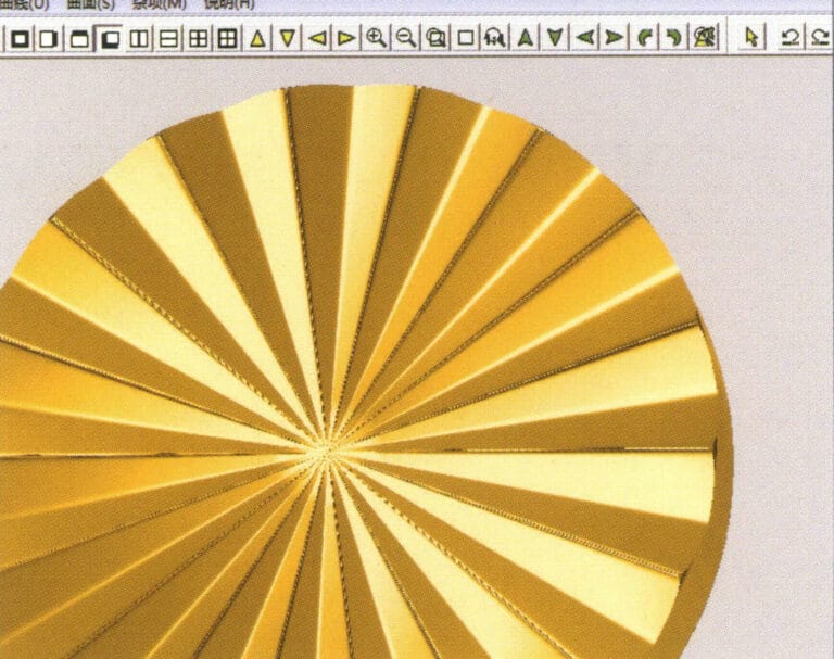
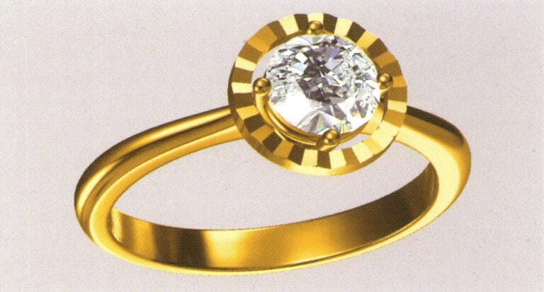
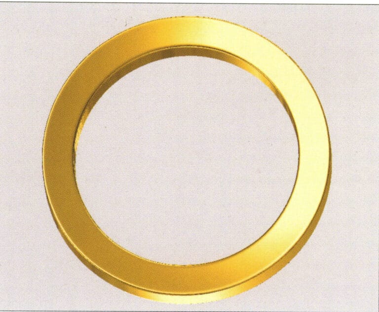
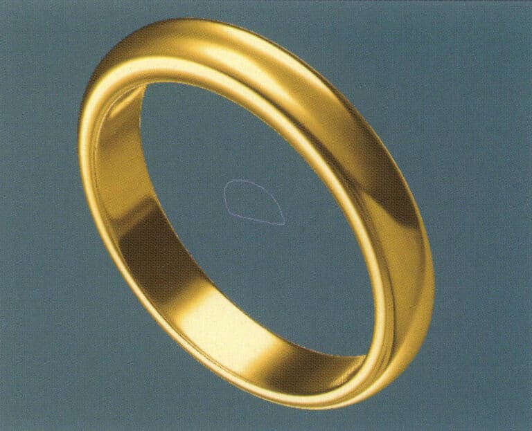
Ring mit gedrehter Diamantfassung
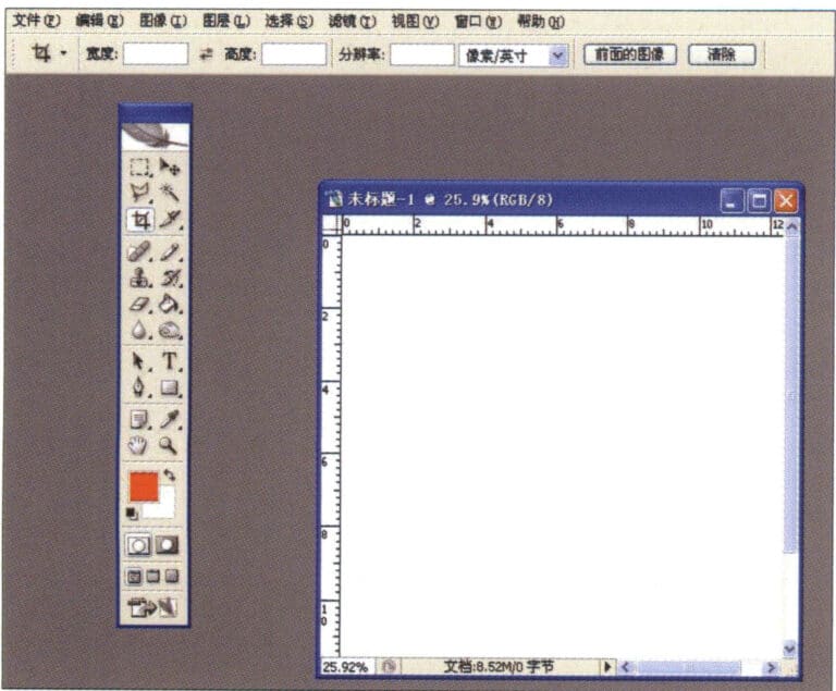
1. Erstellen Sie eine neue Datei in Photoshop mit einer Auflösung von 300 Pixel/Zoll
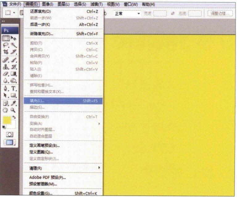
2. Wählen Sie in der Menüleiste "Bearbeiten" > "Füllen" und setzen Sie die Vordergrundfarbe auf Gelb

3. Wählen Sie in der Menüleiste "Filter" > "Sprenkelt" > "Sprenkelt hinzufügen".
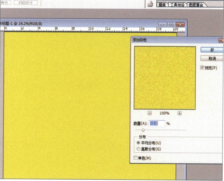
4. Öffnen Sie das Dialogfeld "Mottled hinzufügen", geben Sie die entsprechenden Werte ein und bestätigen Sie
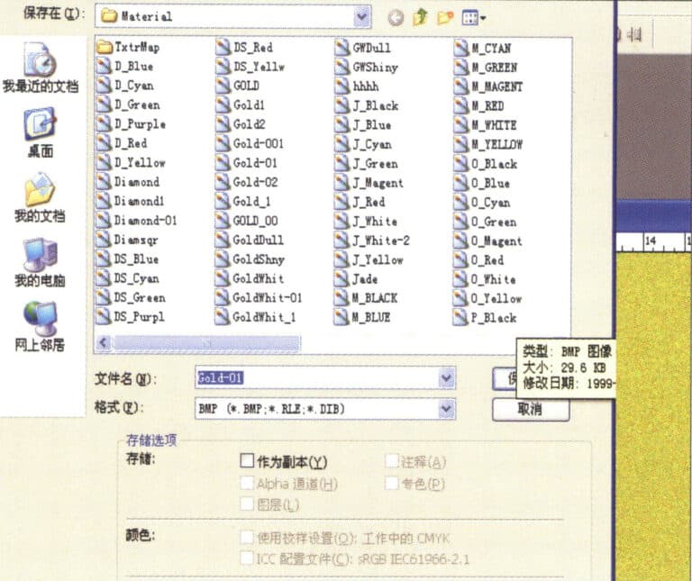
5. Speichern Sie das Dokument im Ordner "JewelCAD" > "Material", gespeichert im Format "BMP".

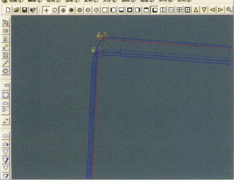
6. Erstellen Sie eine neue Datei in JewelCAD, wählen Sie in der Menüleiste "Fläche" > "Kugeloberfläche".
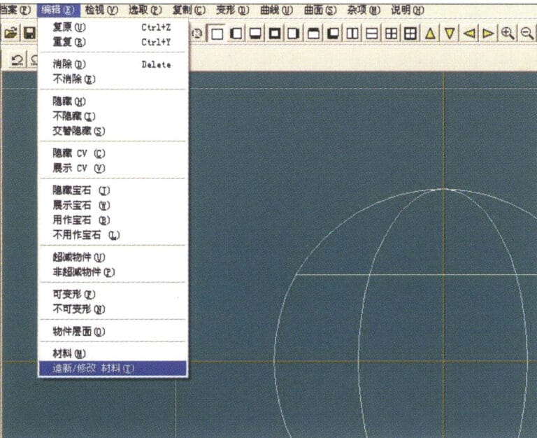
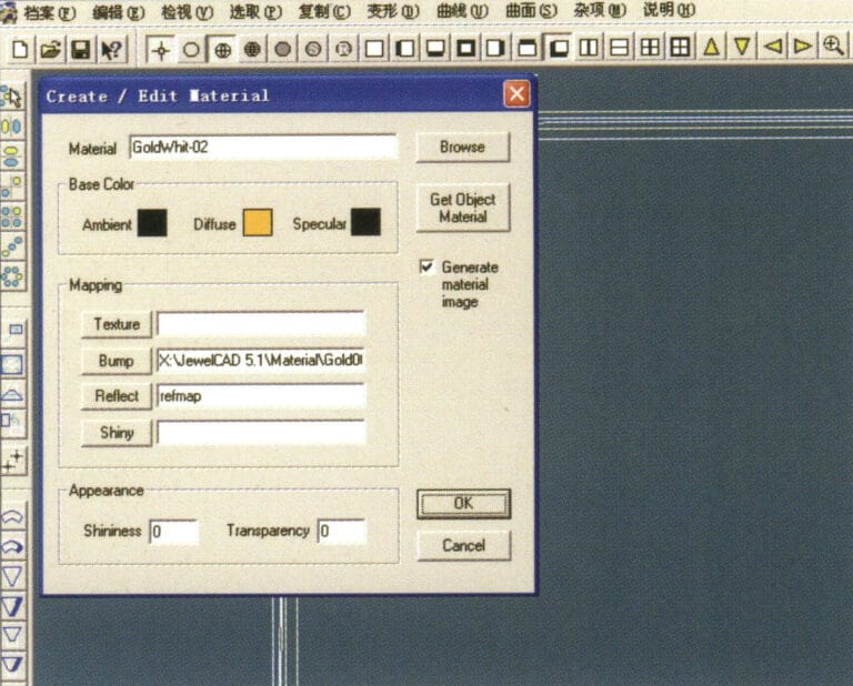
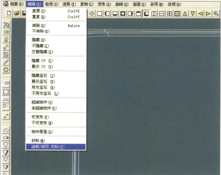
7. Wählen Sie in der Menüleiste "Bearbeiten" > "Material erstellen/bearbeiten".
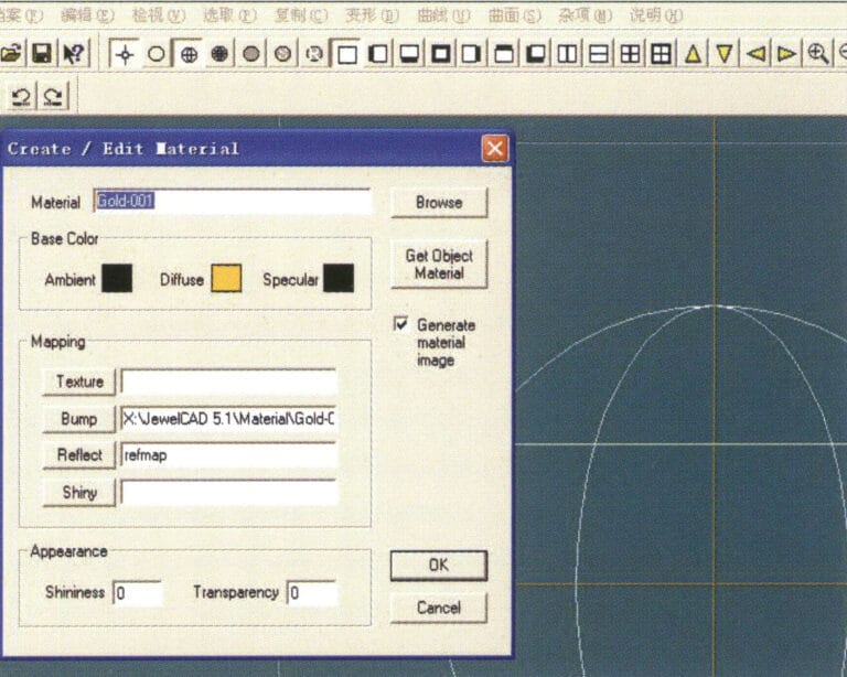
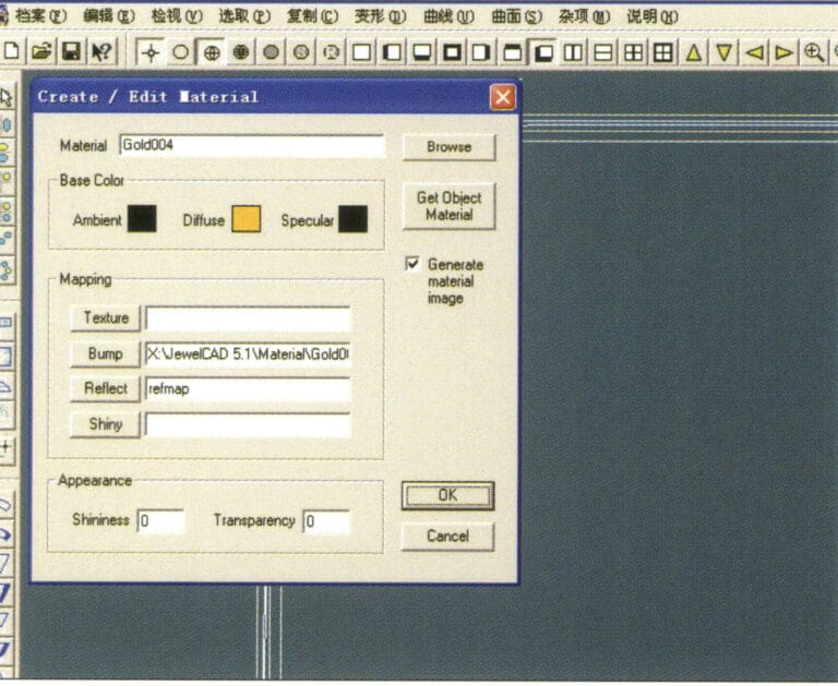
8. Rufen Sie das Dialogfeld "Material erstellen/ändern" auf, geben Sie die entsprechenden Werte ein und bestätigen Sie
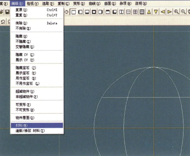
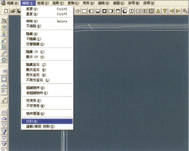
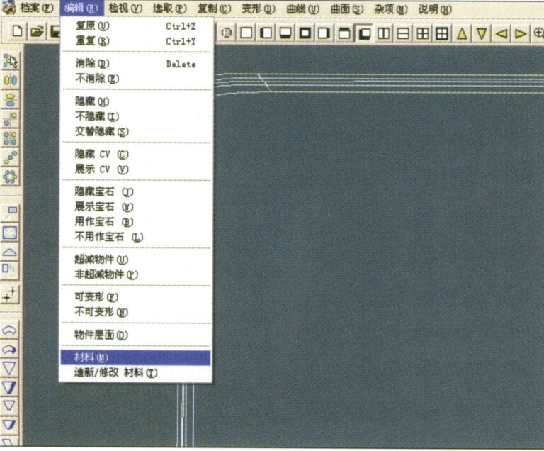
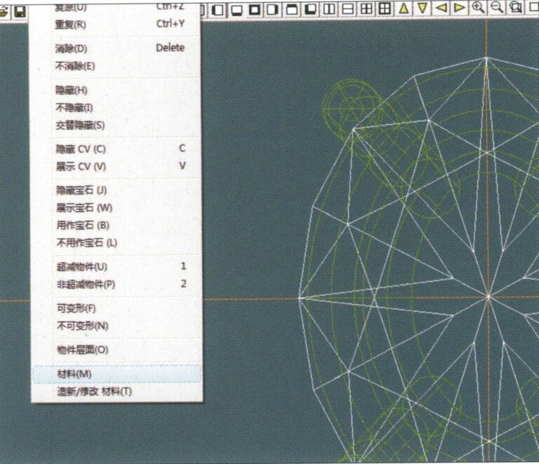
9. Wählen Sie "Bearbeiten" > "Materialien" in der Menüleiste
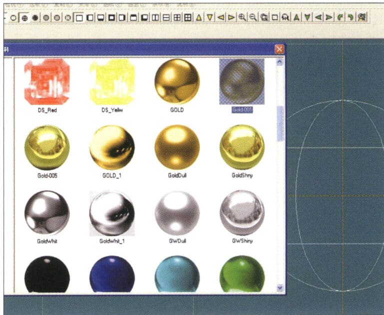
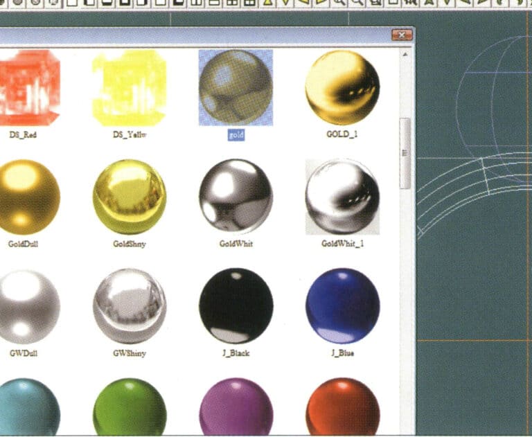
10. Öffnen Sie das Dialogfeld "Materialien", wählen Sie das Material aus und bestätigen Sie
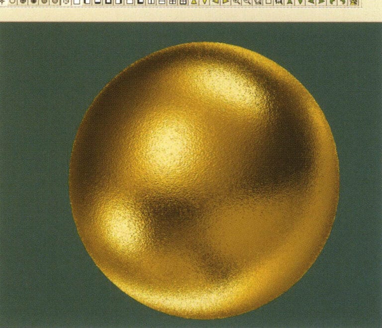
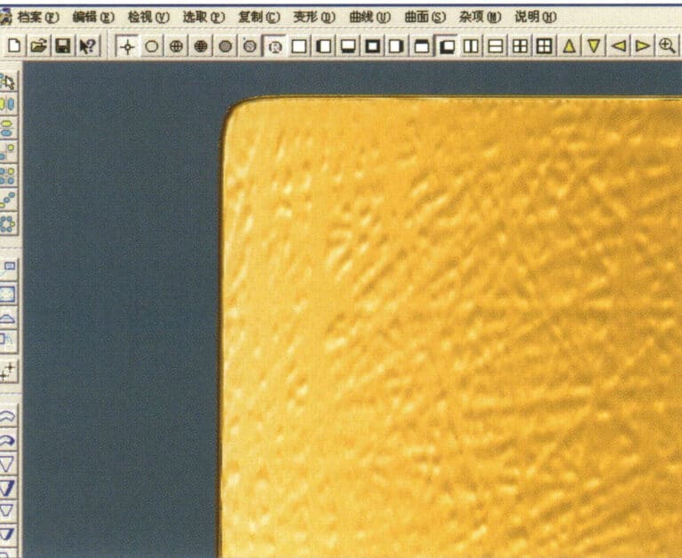
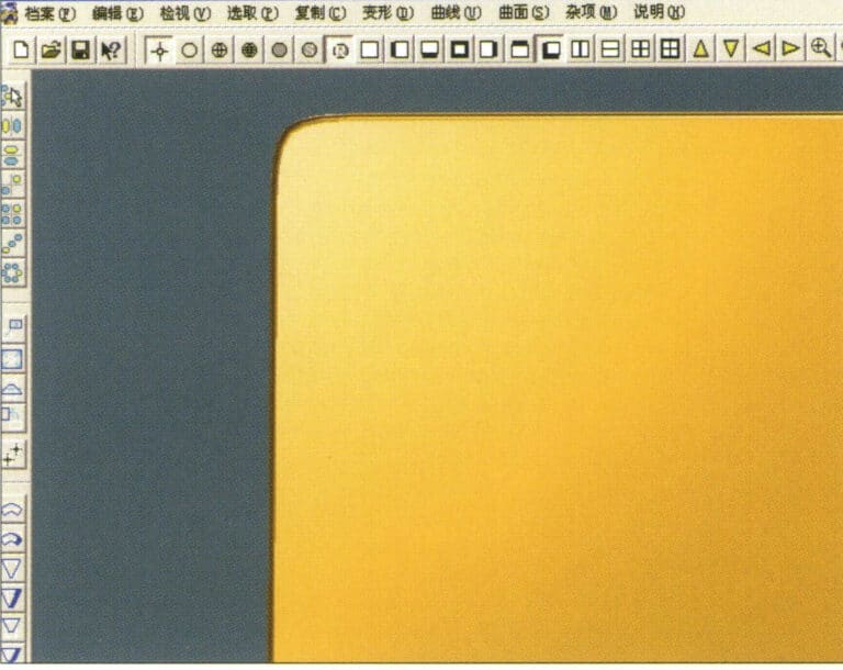
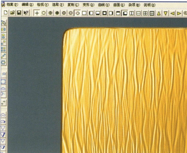
11. Wählen Sie in der Menüleiste "Ansicht" > "Schattenkarte", um die Schatteneffekte zu prüfen.
12. Wählen Sie in der Menüleiste "Datei" > "Datei speichern", um das Dokument zu speichern.

1. Scannen Sie eine Texturdatei in Photoshop mit einer Auflösung von 300 Pixeln/Zoll und wählen Sie in der Menüleiste "Filter" > "Weichzeichnen" > "Bewegungsunschärfe", um den Weichzeichnungseffekt anzuwenden
2. Öffnen Sie das Dialogfeld "Bewegungsunschärfe", geben Sie die entsprechenden Werte ein und bestätigen Sie
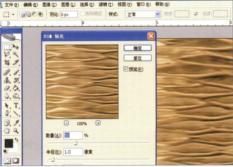
3. Wählen Sie in der Menüleiste "Filter" > "Schärfen" > "USM-Schärfung".
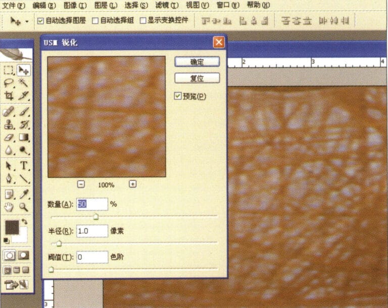
4. Rufen Sie das Dialogfeld "USM-Schärfung" auf, geben Sie die entsprechenden Werte ein und bestätigen Sie
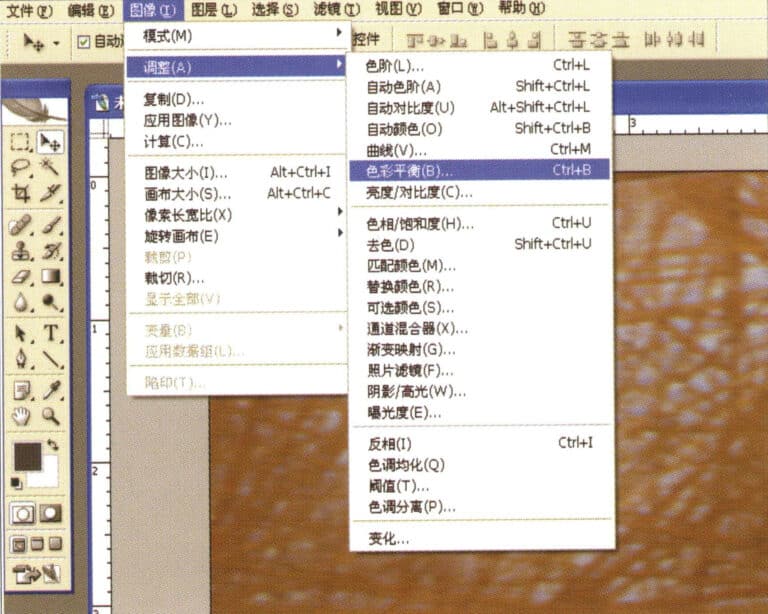
5. Wählen Sie in der Menüleiste "Bild" > "Anpassungen" > "Farbbalance".
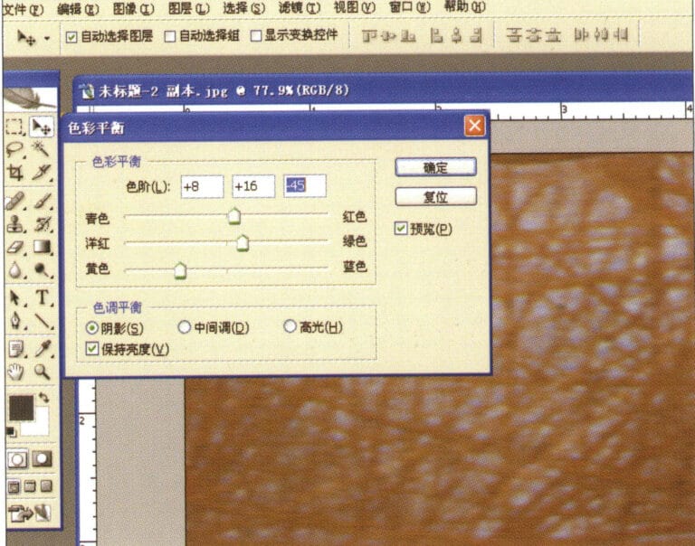
6. Öffnen Sie das Dialogfeld "Farbbalance", geben Sie die entsprechenden Werte ein und bestätigen Sie
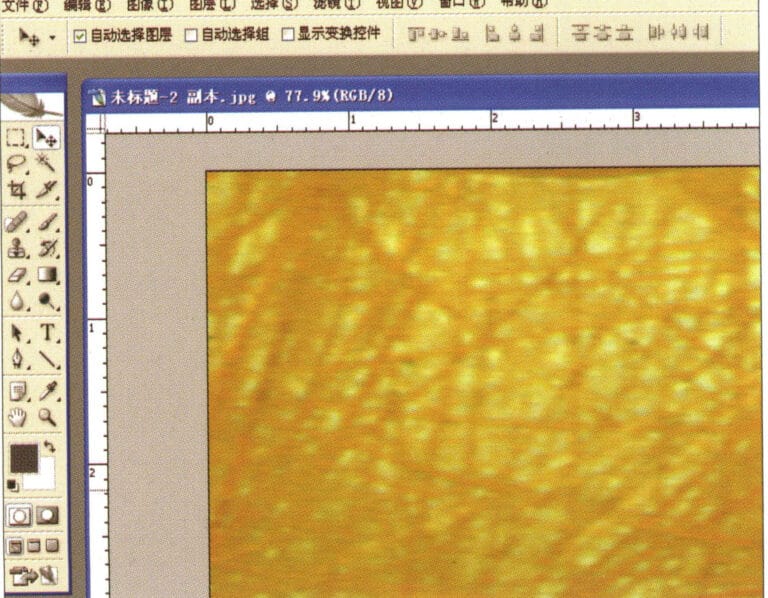
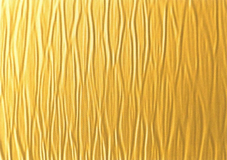
7. Effektdiagramm nach Anzeige der Farbbalance
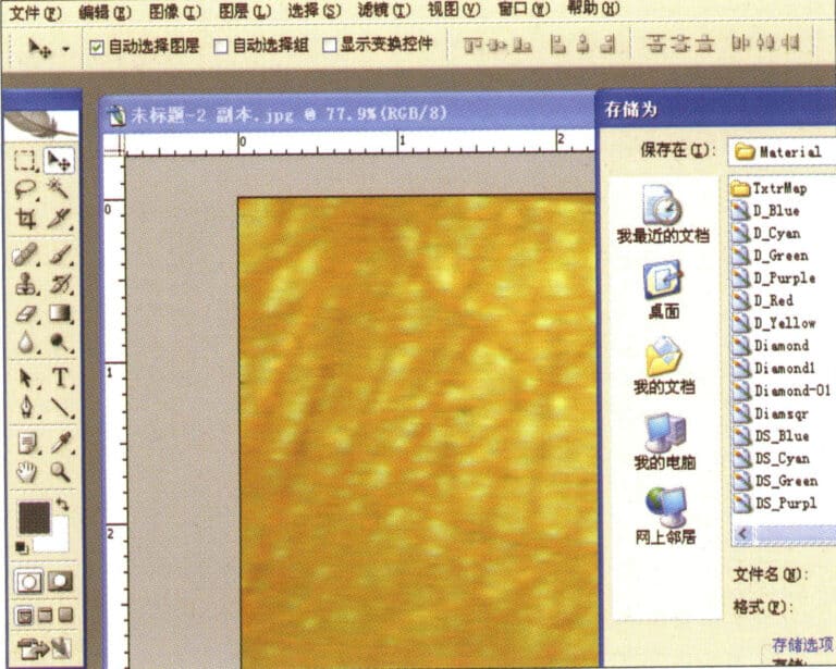
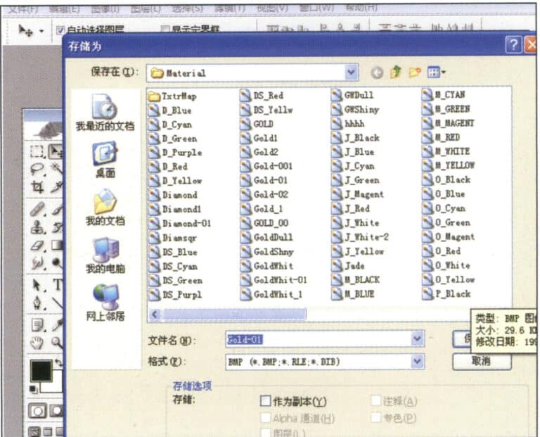
8. Speichern Sie das Dokument im Ordner "JewelCAD" > "Material", gespeichert im Format "BMP".
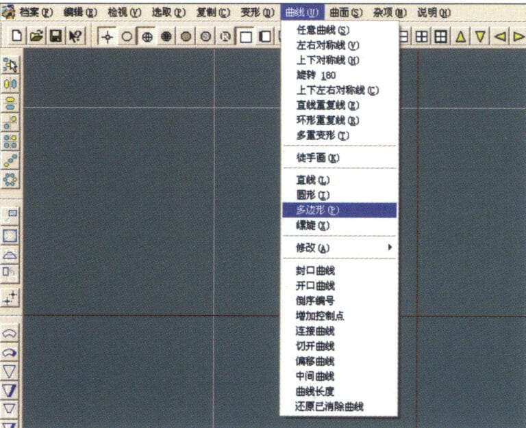
9. Erstellen Sie in JewelCAD eine neue Datei, wählen Sie in der Menüleiste "Kurve" > "Polygon".
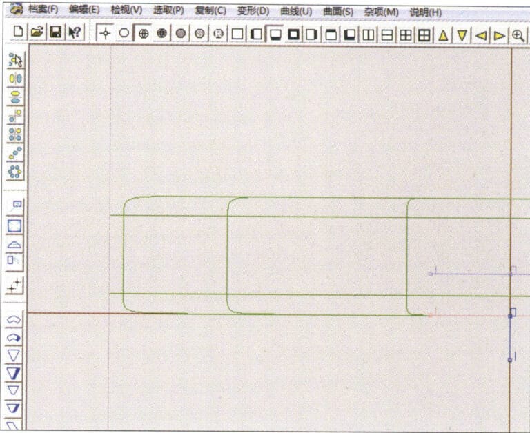
10. Verwenden Sie "Polygon", um ein Quadrat zu zeichnen
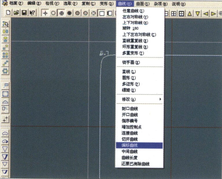
11. Wählen Sie in der Menüleiste "Kurve" > "Offset-Kurve".
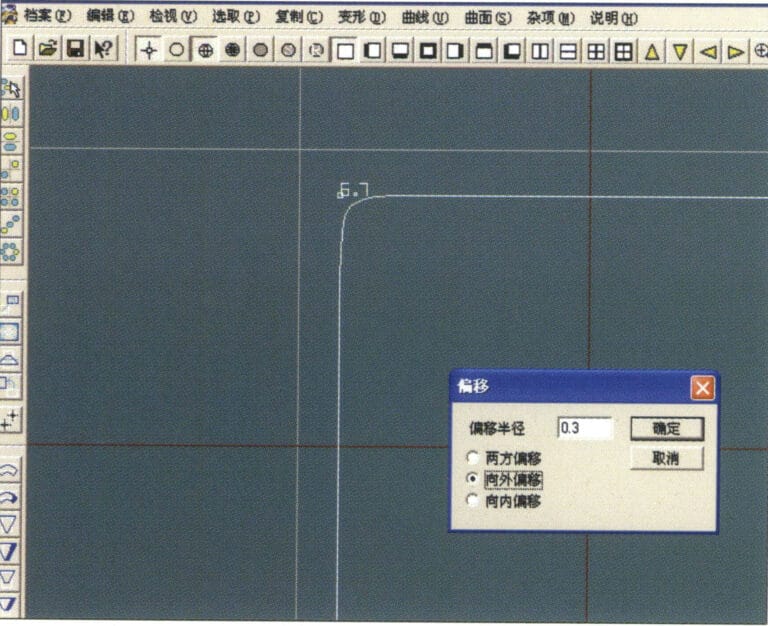
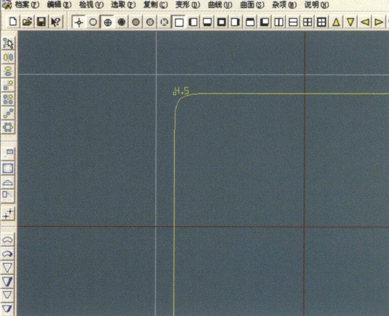
12. Öffnen Sie das Dialogfeld "Offset-Kurve", geben Sie die entsprechenden Werte ein und bestätigen Sie
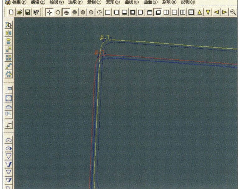
13. Wirkungsdiagramm nach Anzeige der Offsetkurve
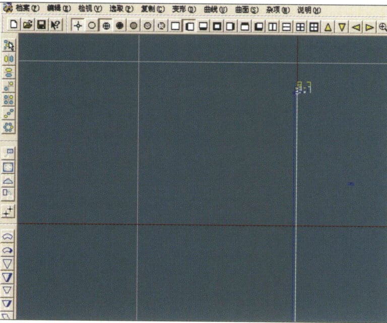
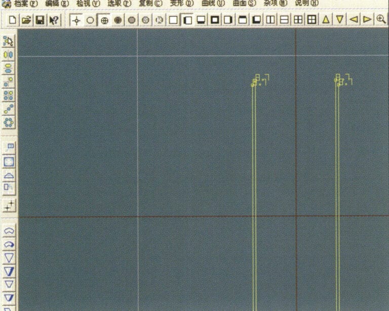
14. Wählen Sie in der Menüleiste "Verformung" > "Verschieben", um die ausgewählte Kurve zu verschieben
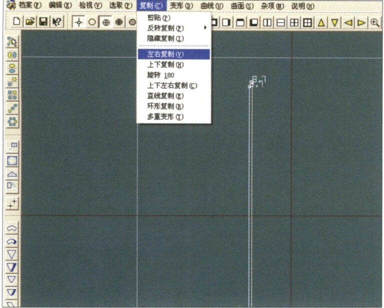
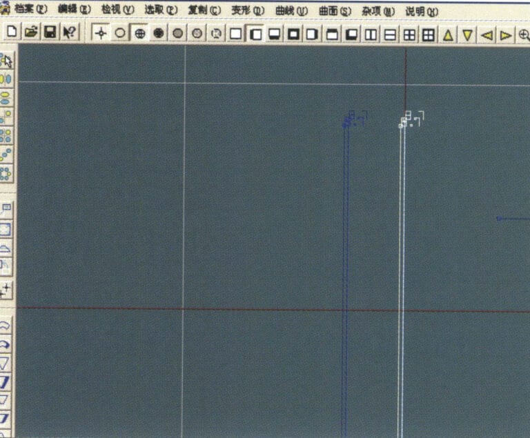
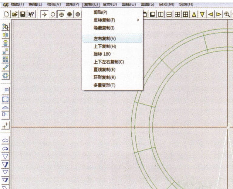
15. Wählen Sie "Kopieren" > "Links und rechts kopieren" in der Menüleiste, um die ausgewählte Kurve nach links und rechts zu kopieren.

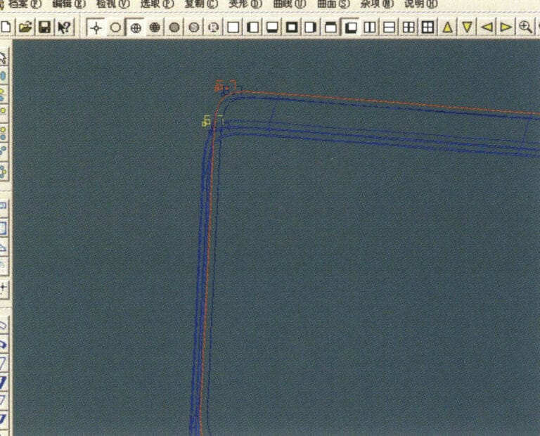
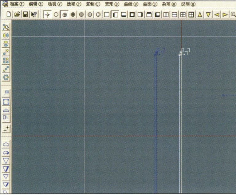
16. Anzeige der Effektbilder nach linker und rechter Vervielfältigung
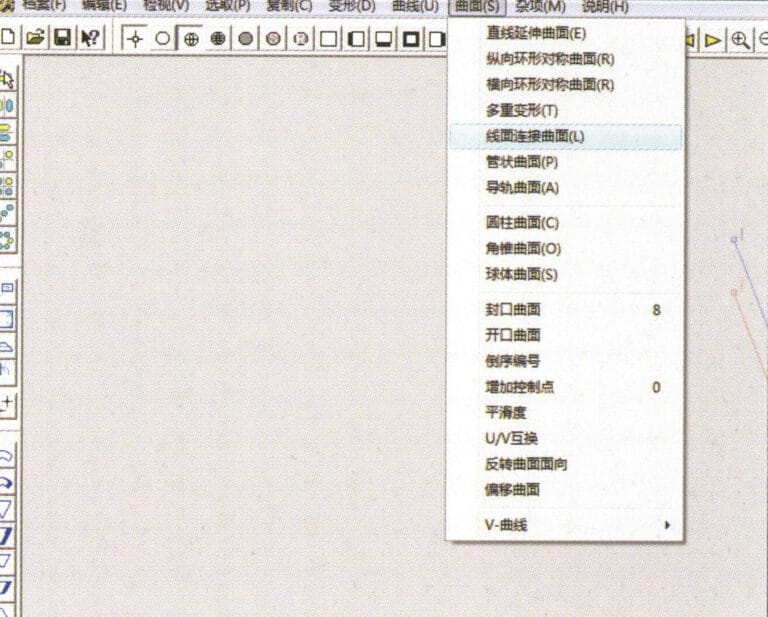
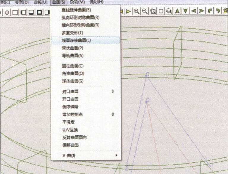
17. Wählen Sie in der Menüleiste "Fläche" > "Kurvenflächenverbindung" und doppelklicken Sie mit der linken Maustaste im Uhrzeigersinn auf die erste und zweite Kurve/Fläche, um eine Kurvenflächenverbindung zu erstellen
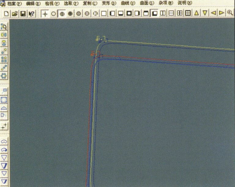
18. Doppelklicken Sie im Uhrzeigersinn mit der linken Maustaste auf die dritte Kurve/Fläche, um eine Linien-Flächen-Verbindung zu erstellen
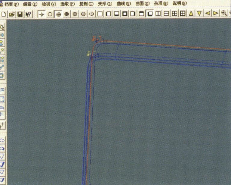
19. Fahren Sie im Uhrzeigersinn fort; doppelklicken Sie mit der linken Maustaste auf die vierte Kurve/Fläche, um eine Linien-Flächen-Verbindung zu erstellen

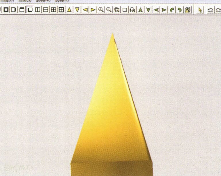
20. Wählen Sie in der Menüleiste "Ansicht" > "Schattenkarte", um die Schatteneffekte zu prüfen
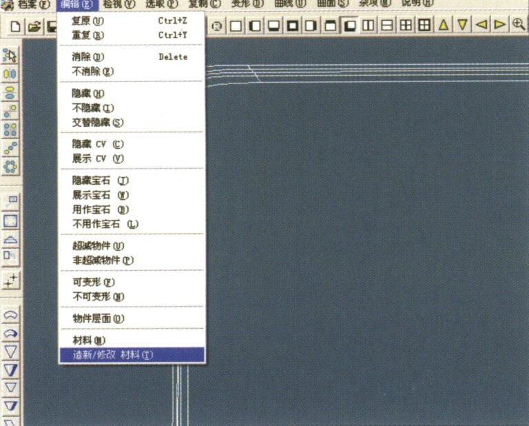
21. Wählen Sie in der Menüleiste "Bearbeiten" > "Material erstellen/bearbeiten".
22. Rufen Sie das Dialogfeld "Material erstellen/ändern" auf, geben Sie die entsprechenden Werte ein und bestätigen Sie
23. Wählen Sie "Bearbeiten" > "Materialien" in der Menüleiste
24. Wählen Sie in der Menüleiste "Ansicht" > "Schattenkarte", um die Licht- und Schatteneffekte anzuzeigen. 25. Wählen Sie in der Menüleiste "Datei" > "Datei speichern", um die Datei zu speichern

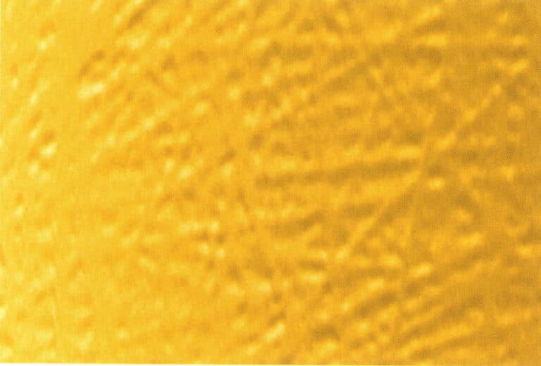
1. Scannen Sie eine Texturdatei in Photoshop mit einer Auflösung von 300 Pixel/Zoll
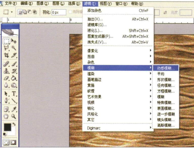
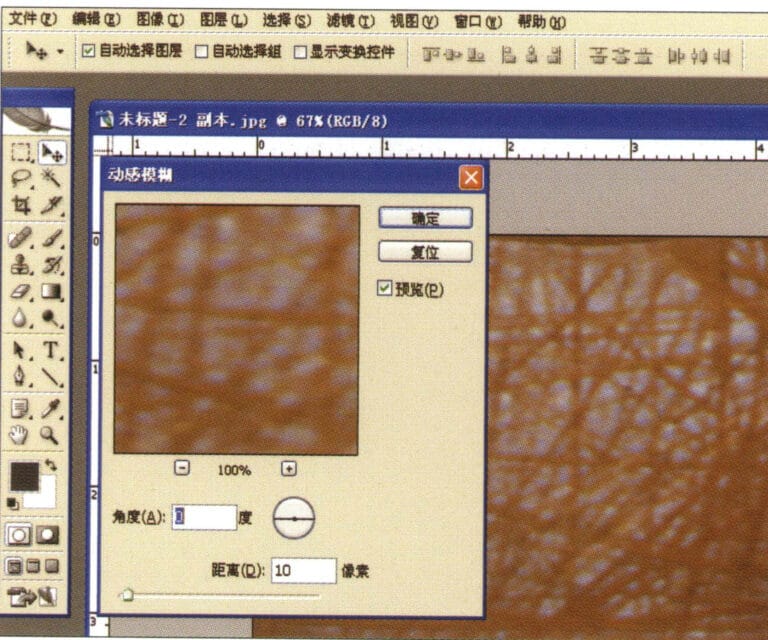
2. Wählen Sie in der Menüleiste "Filter" > "Weichzeichnen" > "Bewegungsunschärfe".
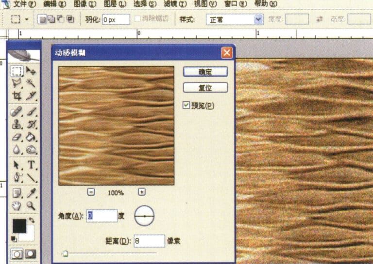
3. Öffnen Sie das Dialogfeld "Bewegungsunschärfe", geben Sie die entsprechenden Werte ein und bestätigen Sie
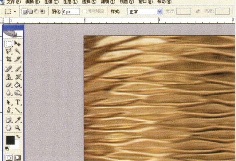
4. Anzeige des Effektbildes nach der Bewegungsunschärfe
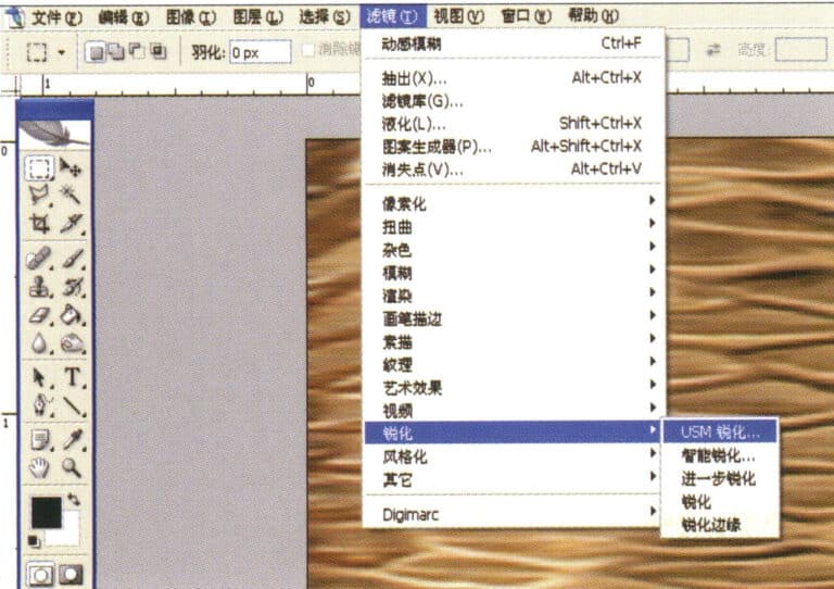
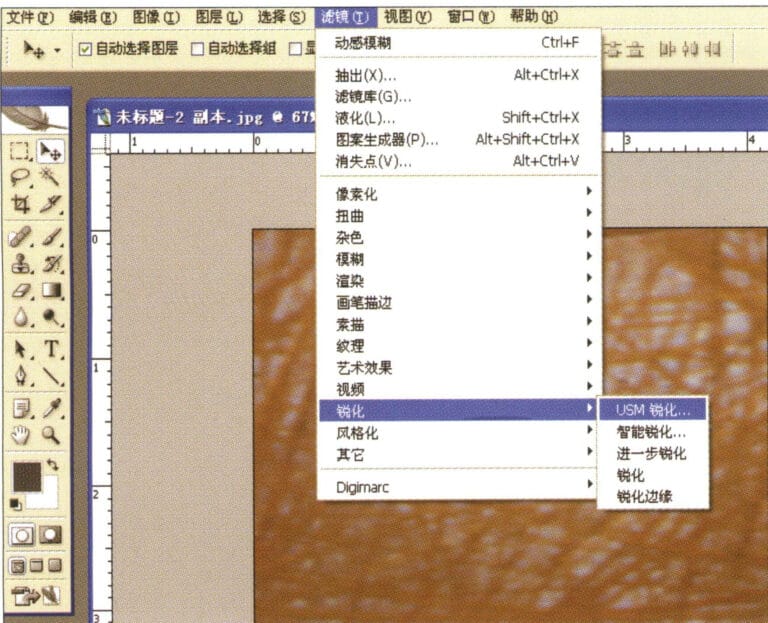
5. Wählen Sie in der Menüleiste "Filter" > "Schärfen" > "USM-Schärfung".
6. Rufen Sie das Dialogfeld "USM-Schärfung" auf, geben Sie die entsprechenden Werte ein und bestätigen Sie
7. Speichern Sie das Dokument im Ordner "JewelCAD" > "Material" und speichern Sie es im Format "BMP".
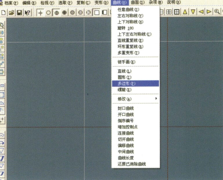
8. Erstellen Sie in JewelCAD eine neue Datei, wählen Sie in der Menüleiste "Kurve" > "Polygon".
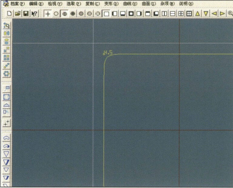
9. Benutze "Polygon", um ein Quadrat zu zeichnen
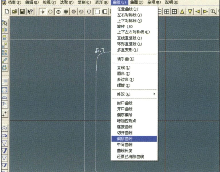
10. Wählen Sie in der Menüleiste "Kurve" > "Offset-Kurve".
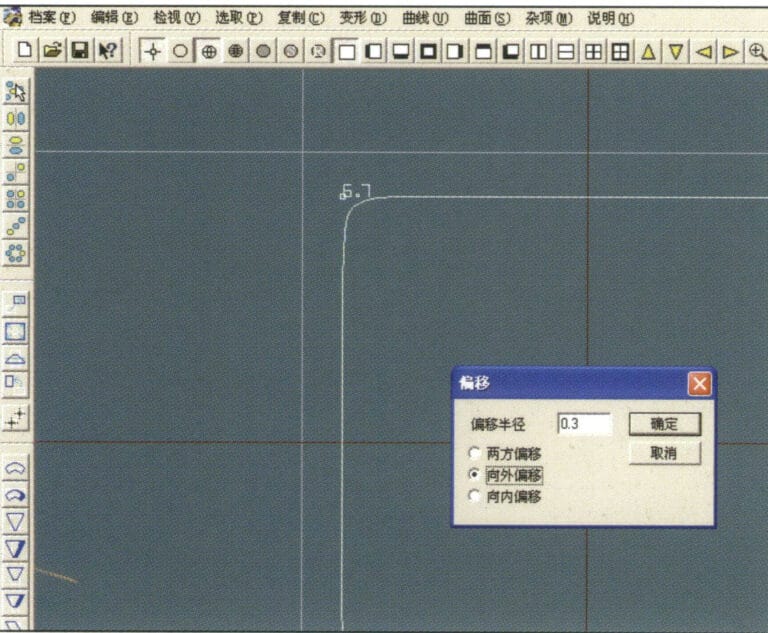
11. Öffnen Sie das Dialogfeld "Offset-Kurve", geben Sie die entsprechenden Werte ein und bestätigen Sie
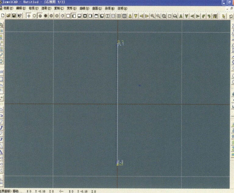
12. Wirkungsdiagramm nach Anzeige der Offsetkurve
13. Wählen Sie in der Menüleiste "Verformung" > "Verschieben", um die ausgewählte Kurve zu verschieben.

14. Wählen Sie in der Menüleiste "Kopieren" > "Links und rechts kopieren", um die ausgewählte Kurve nach links und rechts zu kopieren
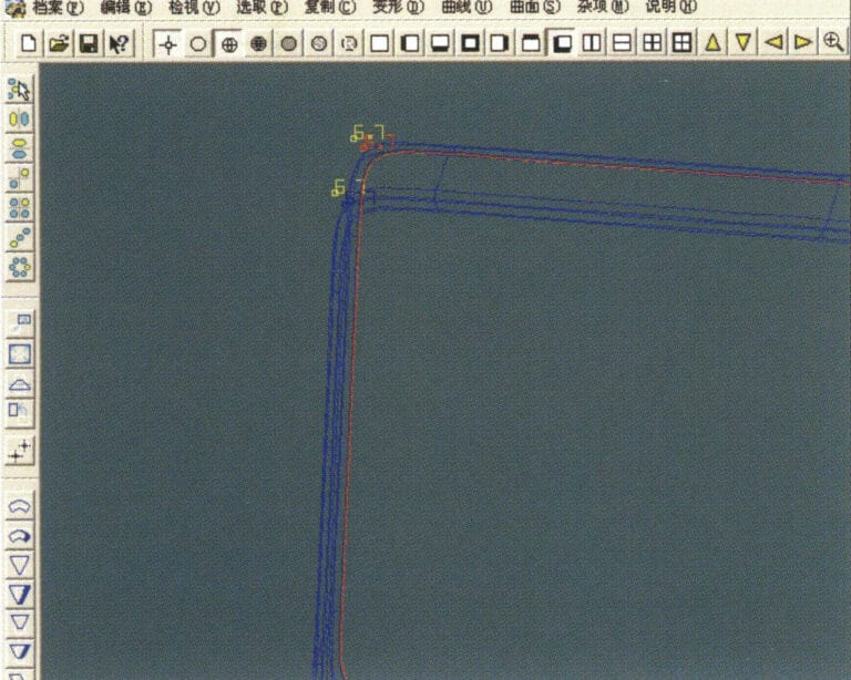
15. Anzeigen der Effektbilder nach dem Kopieren von links und rechts
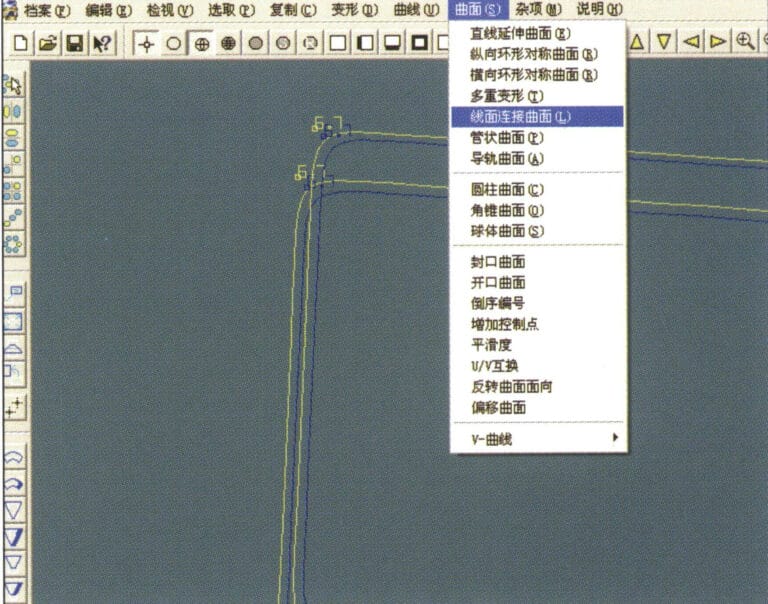
16. Wählen Sie in der Menüleiste "Fläche" > "Linien-Flächen-Verbindungsfläche", und wählen Sie die Kurve/Fläche aus, um eine Linien-Flächen-Verbindungsfläche zu erstellen
17. Wählen Sie die Menüleiste "Fläche" > "Kurvenflächenverbindung" und doppelklicken Sie mit der linken Maustaste im Uhrzeigersinn auf die erste und zweite Kurve/Fläche, um eine Kurvenflächenverbindung zu erstellen
18. Doppelklicken Sie im Uhrzeigersinn mit der linken Maustaste auf die dritte Kurve/Fläche, um eine Linien-Flächen-Verbindung zu erstellen
19. Fahren Sie im Uhrzeigersinn fort; doppelklicken Sie mit der linken Maustaste auf die vierte Kurve/Fläche, um eine Linien-Flächen-Verbindung zu erstellen
20. Wählen Sie in der Menüleiste "Ansicht" > "Schattenkarte", um die Schatteneffekte zu prüfen
21. Wählen Sie in der Menüleiste "Bearbeiten" > "Material erstellen/bearbeiten".
22. Rufen Sie das Dialogfeld "Material erstellen/ändern" auf, geben Sie die entsprechenden Werte ein und bestätigen Sie
23. Wählen Sie in der Menüleiste "Bearbeiten" > "Material".
24. Wählen Sie "Ansicht" > "Schattenkarte" in der Menüleiste, um die Schatteneffekte zu untersuchen
25. Wählen Sie in der Menüleiste "Datei" > "Speichern unter", um die Datei zu speichern

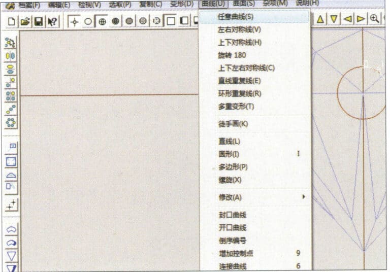
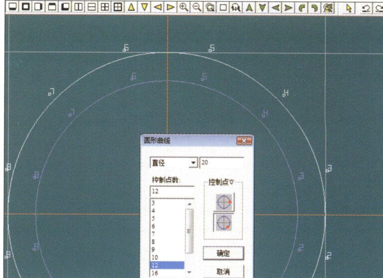
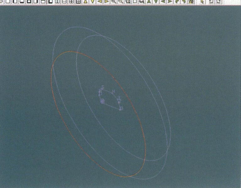
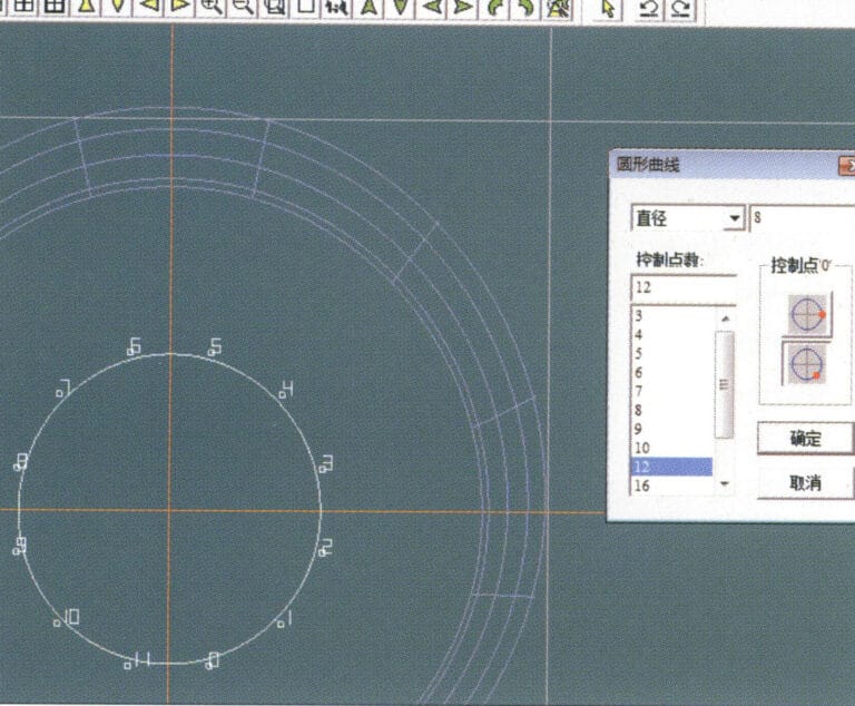
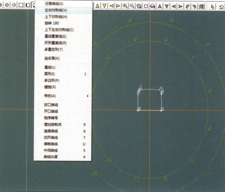
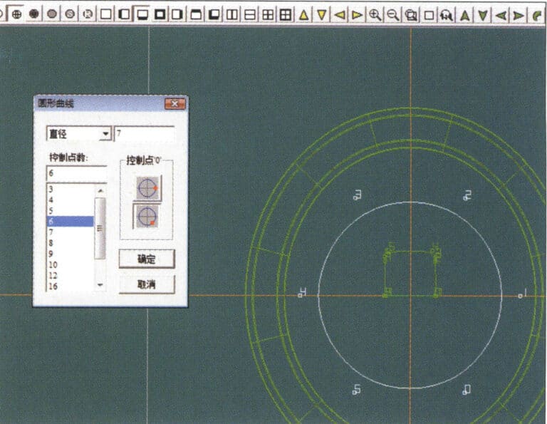
1. Legen Sie in JewelCAD eine neue Datei an, wählen Sie in der Menüleiste "Kurve" > "Kreiskurve", geben Sie im Dialogfeld "Kreiskurve" die entsprechenden Werte ein und bestätigen Sie
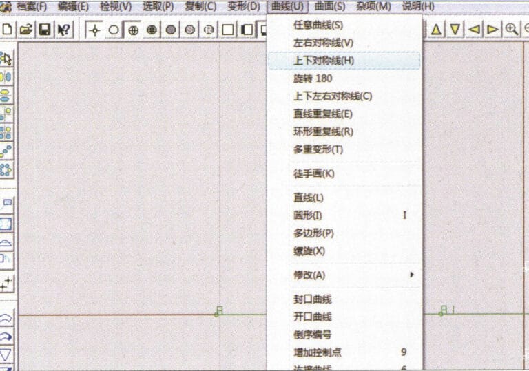
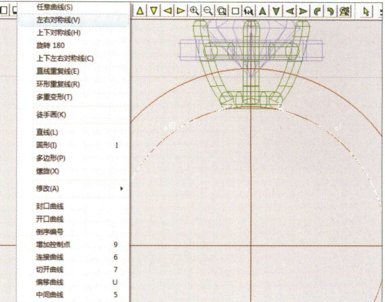
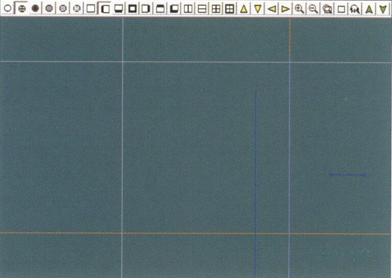
2. Wählen Sie "Kurve" > "Links-Rechts-Symmetrielinie" in der Menüleiste, um einen Schnitt zu zeichnen
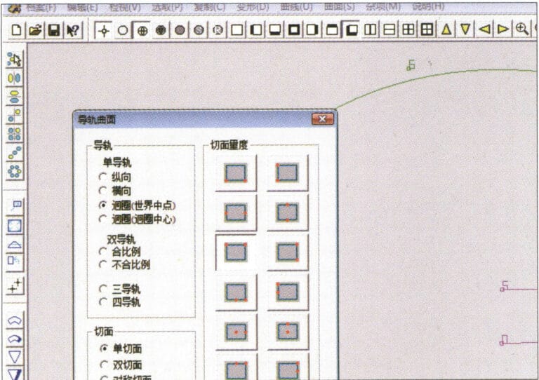
3. Wählen Sie in der Menüleiste "Oberfläche" > "Schienenoberfläche", geben Sie "Schienenoberfläche" ein, wählen Sie die entsprechenden Optionen und bestätigen Sie; klicken Sie mit der linken Maustaste auf eine Kurve als Abschnitt der Schienenoberfläche; klicken Sie mit der linken Maustaste auf eine andere Kurve als "Schiene" > "Fertigstellen".

4. Wählen Sie "Ansicht" > "Schattenkarte" in der Menüleiste, um die Licht- und Schatteneffekte anzuzeigen
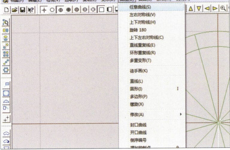
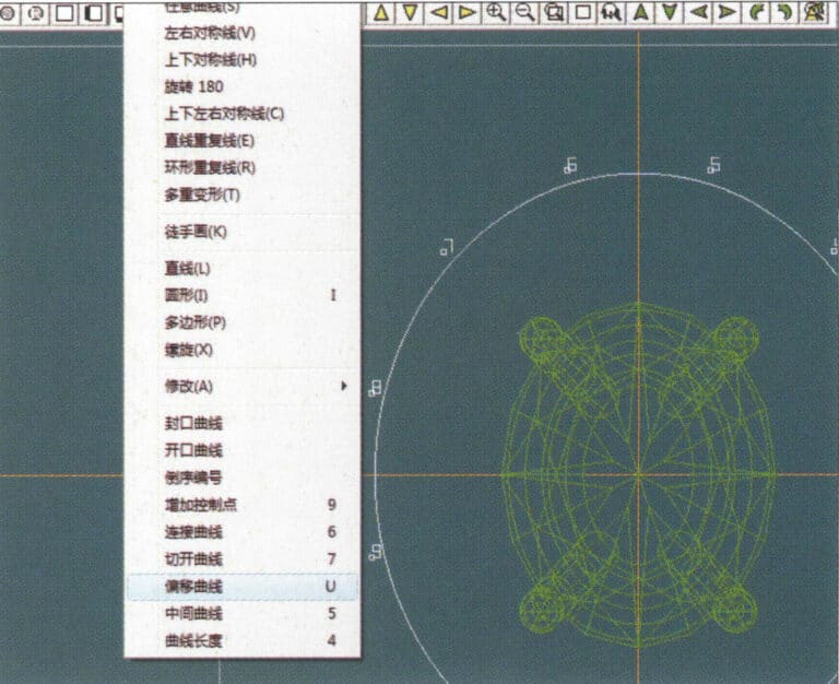
5. Wählen Sie in der Menüleiste "Kurve" > "Freefrom-Kurve".
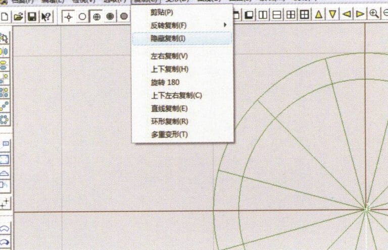
6. Wählen Sie in der Menüleiste "Kopieren" > "Kopie ausblenden".
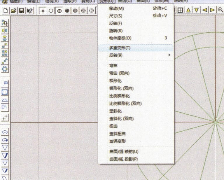
7. Wählen Sie in der Menüleiste "Verformung" > "Mehrfachverformung".
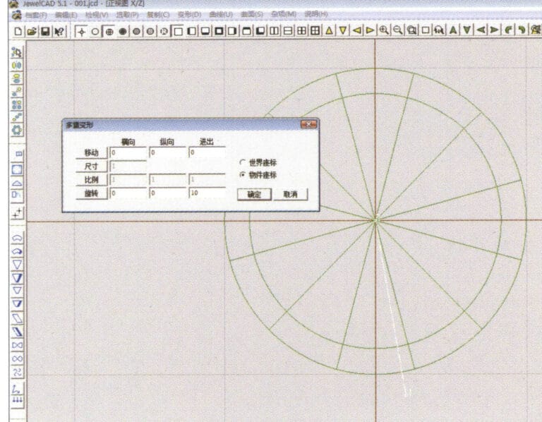
8. Öffnen Sie das Dialogfeld "Mehrfachverformung" und geben Sie die entsprechenden Werte ein
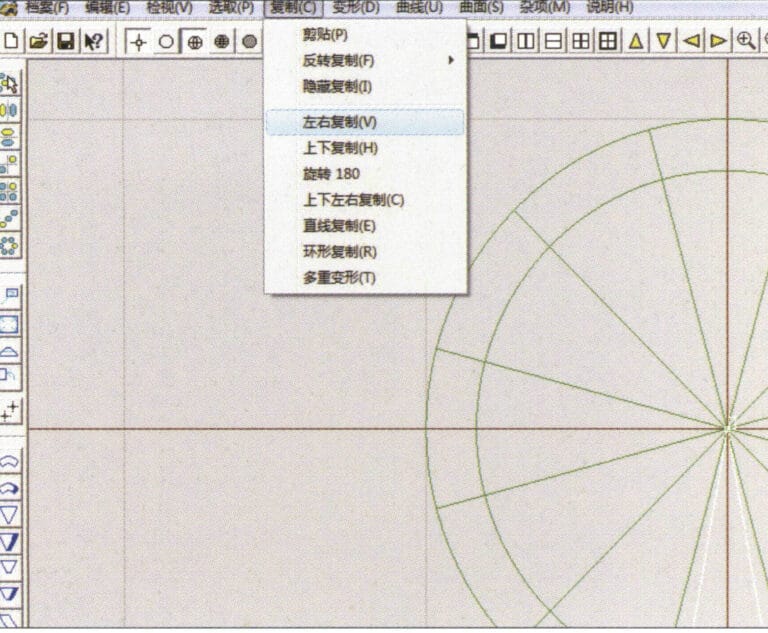
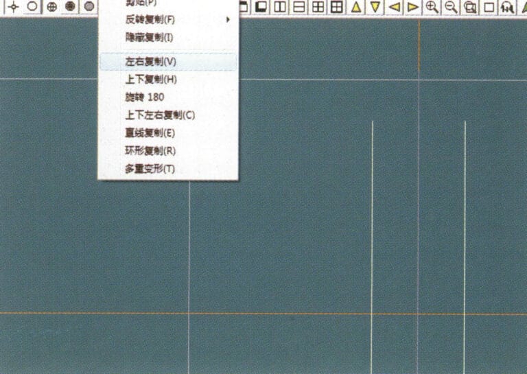
9. Wählen Sie "Kopieren" > "Links/Rechts-Kopie" in der Menüleiste
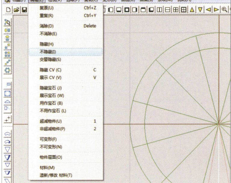
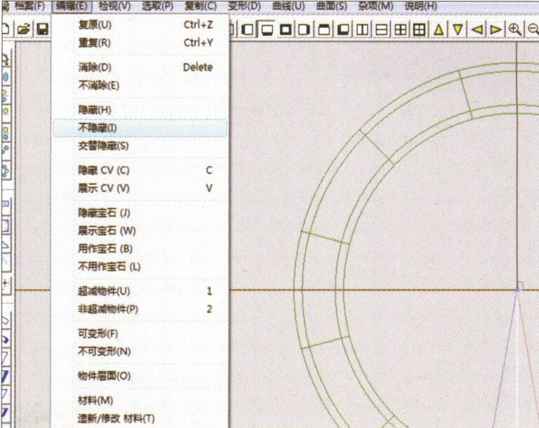
10. Wählen Sie in der Menüleiste "Bearbeiten" > "Einblenden", um die ausgeblendeten Kurven anzuzeigen
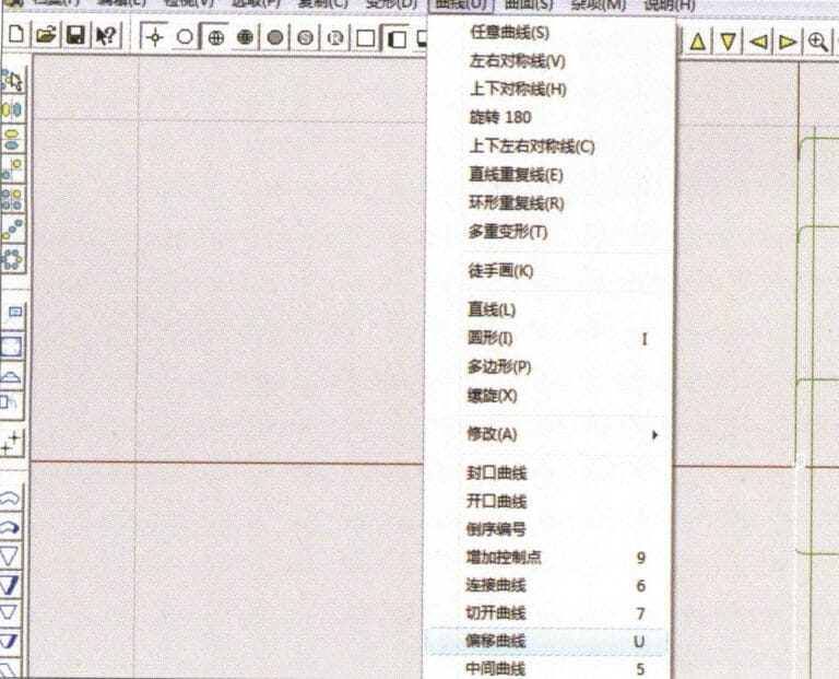
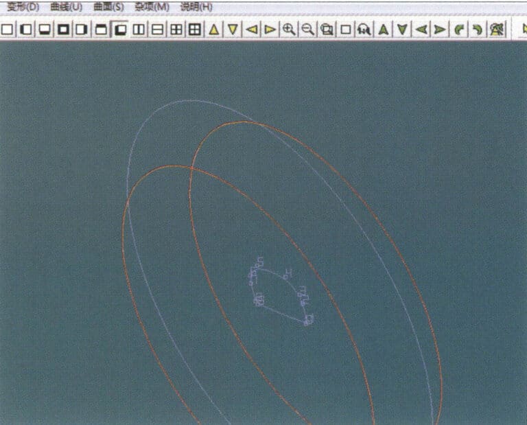
11. Wählen Sie in der Menüleiste "Kurve" > "Offset-Kurve".
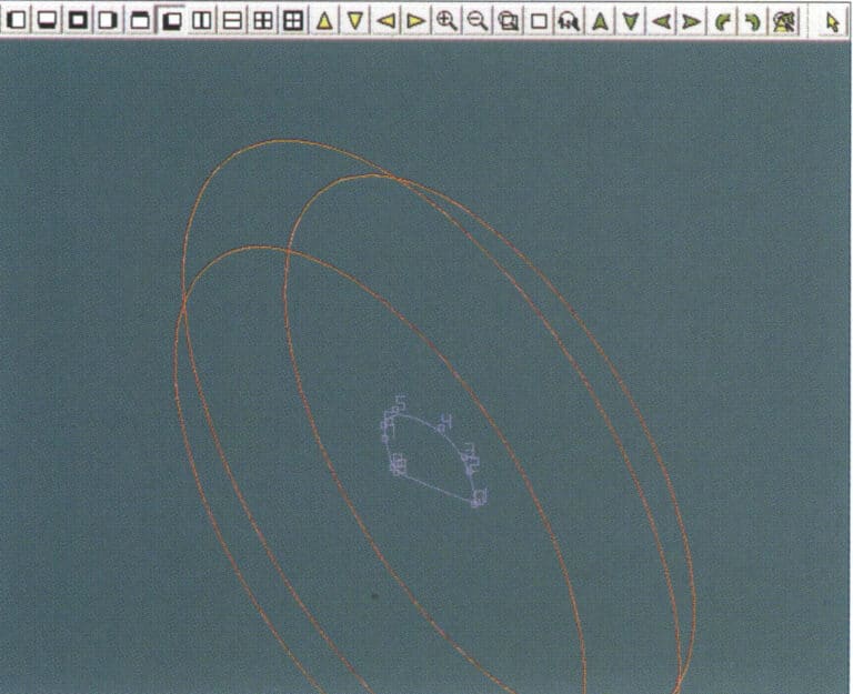
12. Wählen Sie in der Menüleiste "Verformung" > "Verschieben", um die ausgewählte Kurve zu verschieben
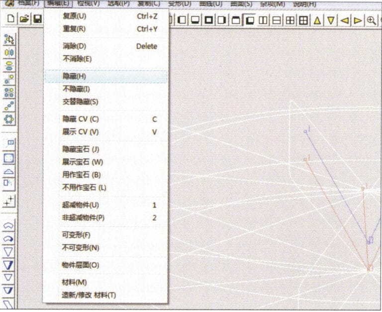
13. Wählen Sie in der Menüleiste "Bearbeiten" > "Ausblenden", um die Kreisfläche auszublenden
14. Wählen Sie in der Menüleiste "Fläche" > "Linie Fläche Anschlussfläche".

15. Wählen Sie Kurven/Flächen im Uhrzeigersinn, um Linien-Flächen-Verbindungen zu erstellen, und wählen Sie dann in der Menüleiste
16. Wählen Sie in der Menüleiste "Ansicht" > "Schattenkarte", um die Schatteneffekte zu prüfen
17. Wählen Sie in der Menüleiste "Bearbeiten" > "Einblenden", um die ausgeblendeten Kreisflächen anzuzeigen
18. Wählen Sie in der Menüleiste "Verformung" > "Verschieben", um die ausgewählte Fläche zu verschieben.
19. Wählen Sie in der Menüleiste "Kopieren" > "Zirkuläre Kopie", geben Sie die entsprechenden Werte ein und bestätigen Sie

20. Wählen Sie in der Menüleiste "Verschiedenes" > "Boolesch" > "Integrieren", um die ausgewählten Flächen zu integrieren.
21. Wählen Sie in der Menüleiste "Verschiedenes" > "Boolesch" > "Subtrahieren", um die ausgewählte Fläche von der bereits vereinigten Fläche zu subtrahieren
22. Wählen Sie in der Menüleiste "Ansicht" > "Schattenkarte", um die Schatteneffekte zu prüfen.
23. Wählen Sie in der Menüleiste "Datei" > "Datei speichern", um das Dokument zu speichern.
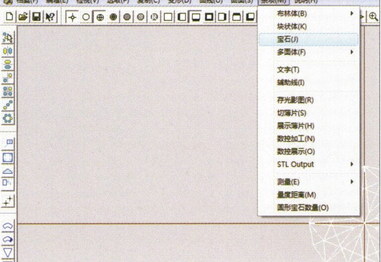
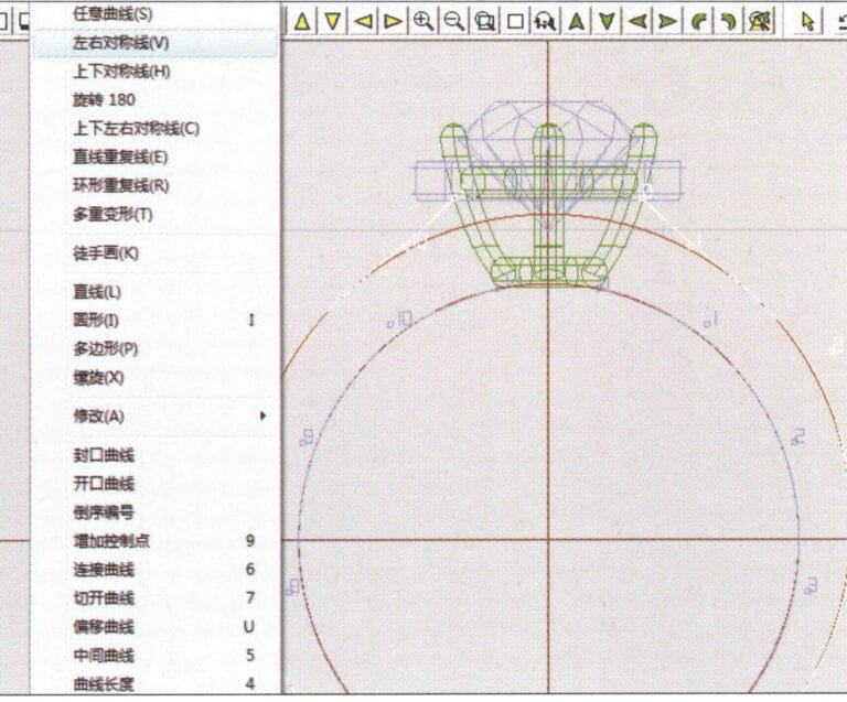
1. Erstellen Sie eine neue Datei in JewelCAD, wählen Sie "Verschiedenes" > "Edelstein" in der Menüleiste

2. Wählen Sie in der Menüleiste "Verformung" > "Mehrfachverformung".
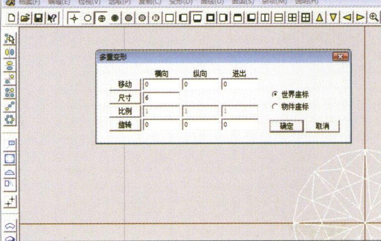
3. Öffnen Sie das Dialogfeld "Mehrfachverformung", geben Sie die entsprechenden Werte ein und bestätigen Sie
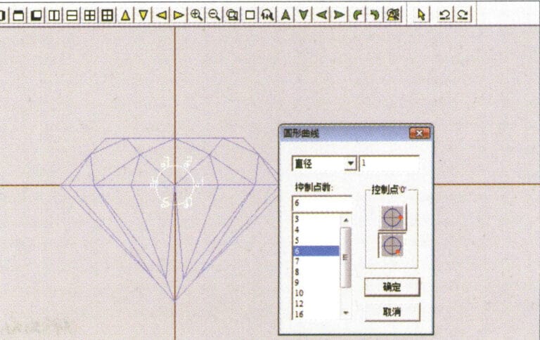
4. Wählen Sie in der Menüleiste "Kurve" > "Kreiskurve", um das Dialogfeld "Kreiskurve" aufzurufen, geben Sie die entsprechenden Werte ein und bestätigen Sie
5. Wählen Sie in der Menüleiste "Kurve" > "Freiformkurve", um eine krallenförmige Hilfslinie zu zeichnen
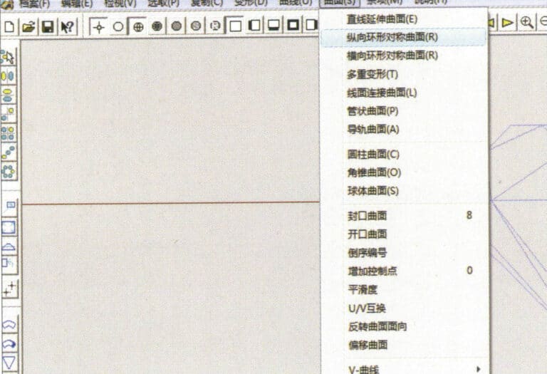
6. Wählen Sie in der Menüleiste "Fläche" > "Längssymmetrische Ringfläche" und zeichnen Sie eine Klauenform
7. Wählen Sie in der Menüleiste "Kurve" > "Kreiskurve", geben Sie die entsprechenden Werte im Dialogfeld "Kreiskurve" ein und bestätigen Sie
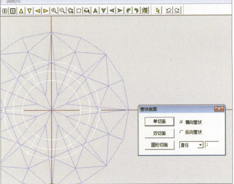
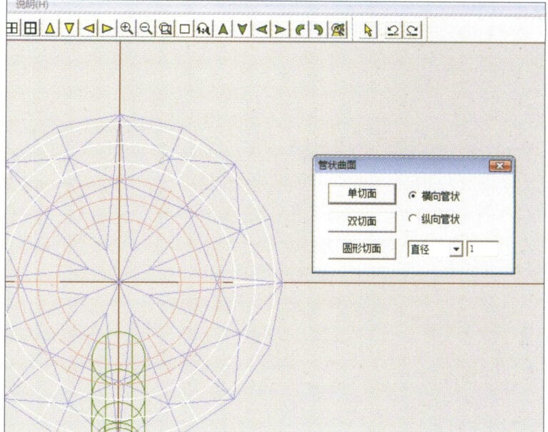
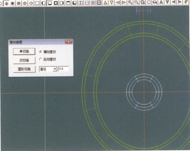
8. Wählen Sie in der Menüleiste "Oberfläche" > "Röhrenoberfläche", geben Sie die entsprechenden Werte ein und bestätigen Sie
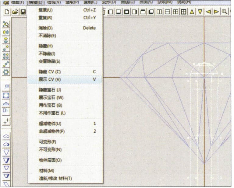
9. Wählen Sie in der Menüleiste "Bearbeiten" > "Lebenslauf anzeigen".
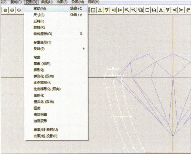
10. Wählen Sie "Verformung" > "Verschieben" in der Menüleiste, um den CV zu verschieben.
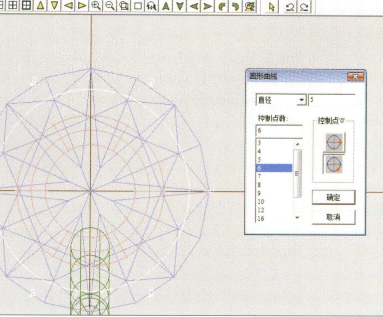
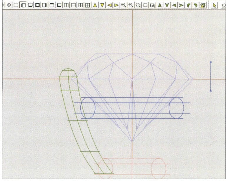
11. Wählen Sie in der Menüleiste "Kurve" > "Kreiskurve", geben Sie die entsprechenden Werte im Dialogfeld "Kreiskurve" ein und bestätigen Sie
12. Wählen Sie in der Menüleiste "Oberfläche" > "Rohroberfläche", geben Sie die entsprechenden Werte ein und bestätigen Sie
13. Wählen Sie die Menüleiste "Bearbeiten" > "Verschieben", um die ausgewählte Grafik zu verschieben

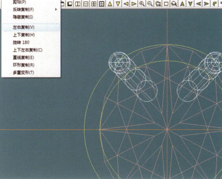
14. Markieren Sie die fertige Krallenform, wählen Sie im Menü "Kopieren" > "Rundkopie", geben Sie im Dialogfeld "Rundkopie" die entsprechenden Werte ein und bestätigen Sie
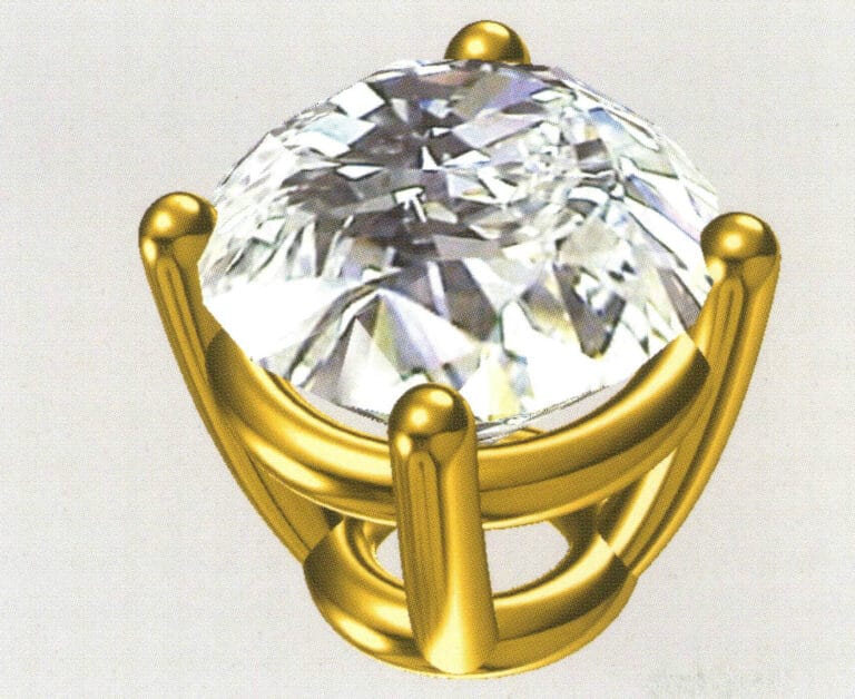
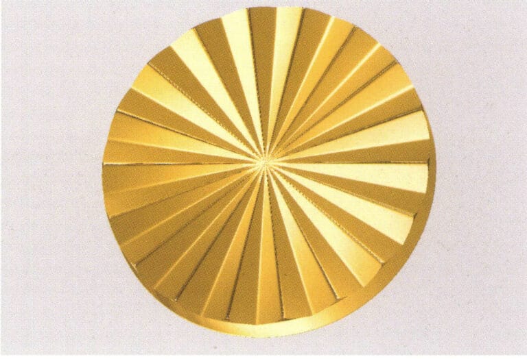
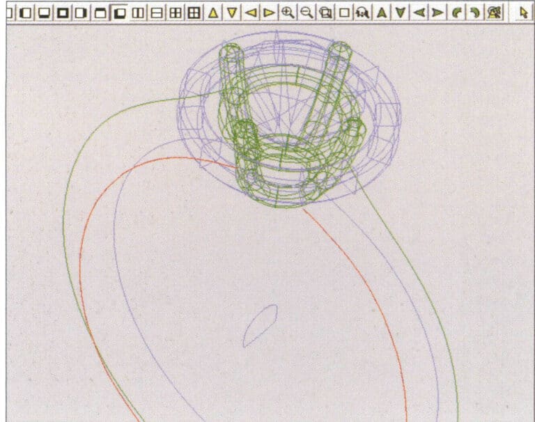
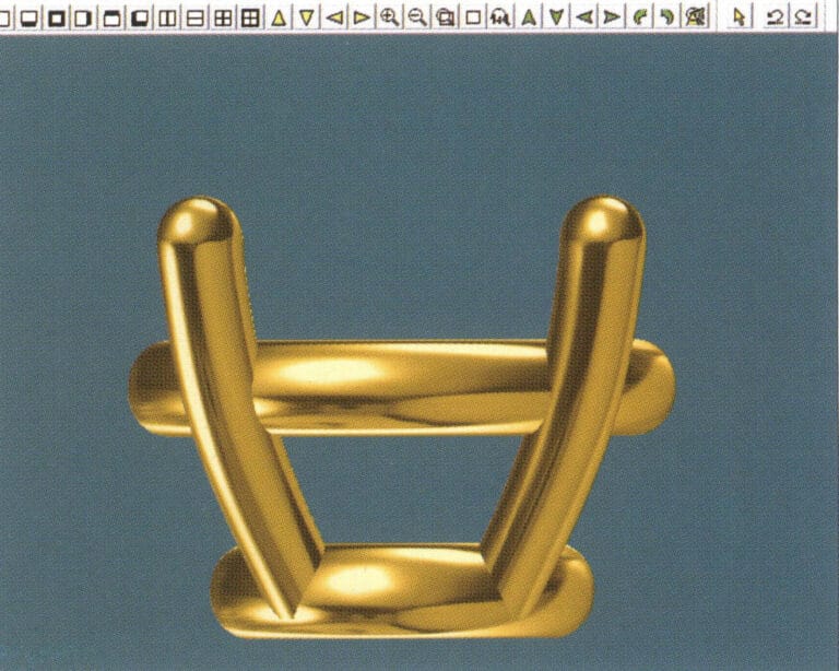
15. Wählen Sie in der Menüleiste "Ansicht" > "Schattenkarte", um die Schatteneffekte zu prüfen
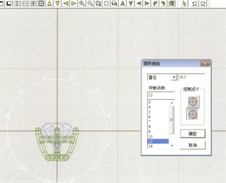
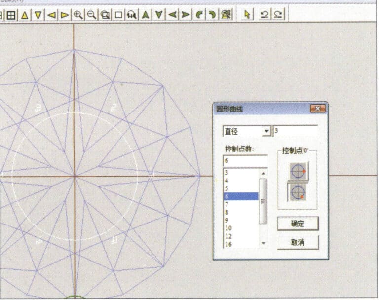
16. Wählen Sie in der Menüleiste "Kurve" > "Kreisförmige Kurve", rufen Sie das Dialogfeld "Kreisförmige Kurve" auf und geben Sie die entsprechenden Werte als Innendurchmesser des Ringschaftes
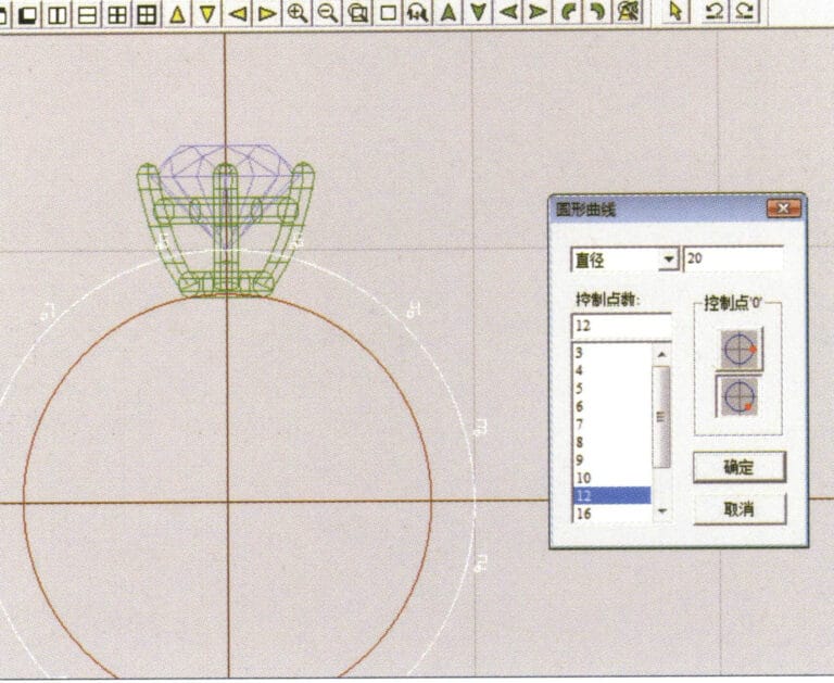
17. Wählen Sie in der Menüleiste "Kurve" > "Kreisförmige Kurve", rufen Sie das Dialogfeld "Kreisförmige Kurve" auf und geben Sie die entsprechenden Werte als Außendurchmesser des Ringschafts ein

18. Wählen Sie in der Menüleiste "Kurve" > "Kreisförmige Kurve", rufen Sie das Dialogfeld "Kreisförmige Kurve" auf und geben Sie die entsprechenden Werte als Außendurchmesser des vom Motor gedrehten Bands ein
19. Wählen Sie in der Menüleiste "Kurve" > "Kreisförmige Kurve", rufen Sie das Dialogfeld "Kreisförmige Kurve" auf und geben Sie die entsprechenden Werte als Innendurchmesser des vom Motor gedrehten Bands
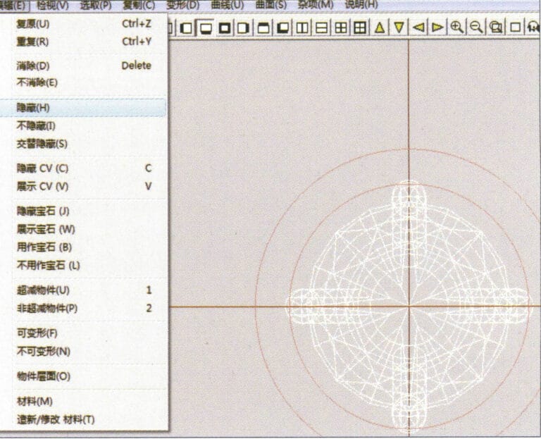
20. Wählen Sie in der Menüleiste "Bearbeiten" > "Ausblenden", um die fertige Edelsteinintarsie auszublenden
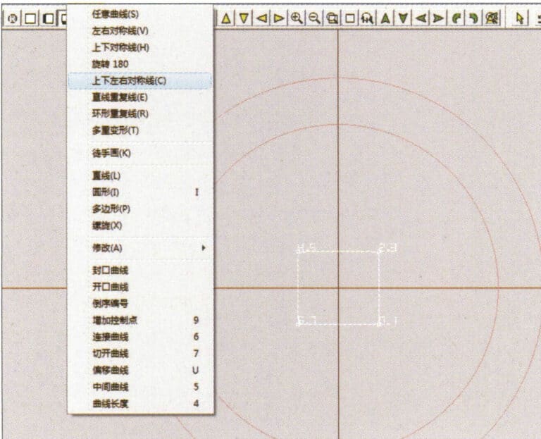
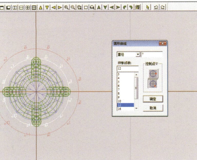
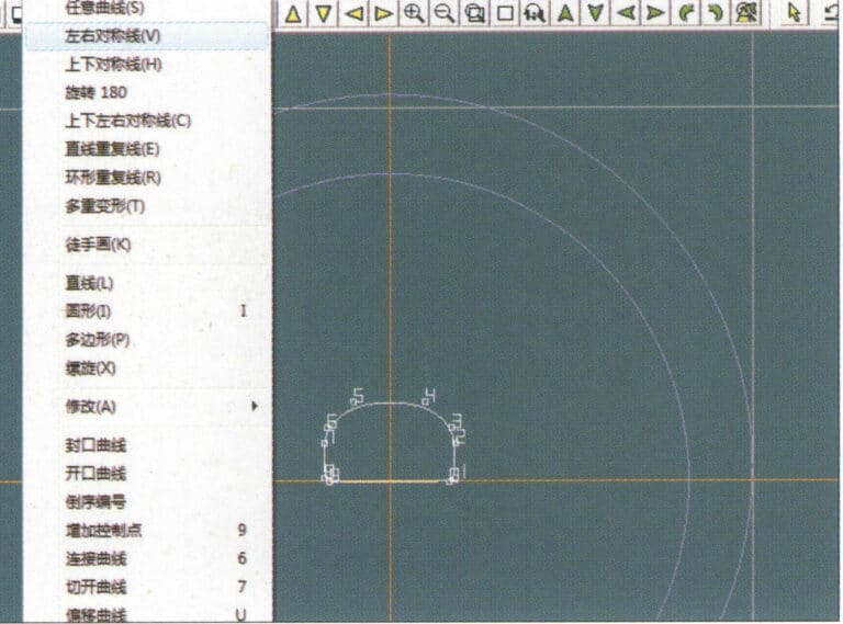
21. Wählen Sie in der Menüleiste "Kurve" > "Vertikale und horizontale Symmetrielinie".
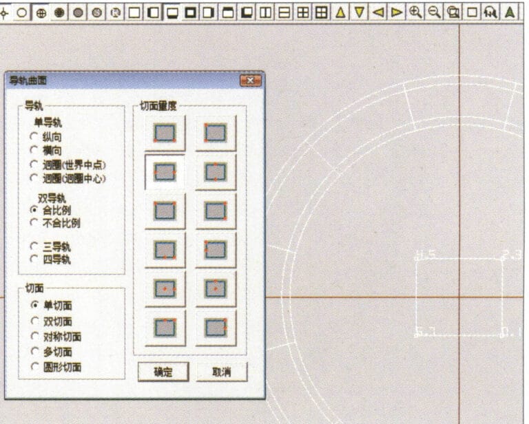
22. Wählen Sie in der Menüleiste "Oberfläche" > "Schienenoberfläche", um das Dialogfeld "Schienenoberfläche" aufzurufen, wählen Sie die entsprechenden Optionen und bestätigen Sie
23. Wählen Sie "Ansicht" > "Schattenkarte" in der Menüleiste, um die Schatteneffekte zu prüfen.
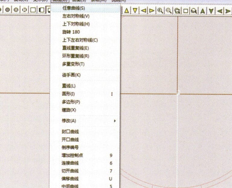
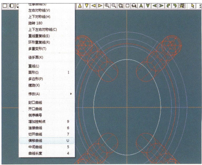
24. Wählen Sie "Kurve" > "Freiformkurve" in der Menüleiste, um eine Hilfslinie zu zeichnen

25. Wählen Sie "Kopieren" > "Kopie ausblenden" in der Menüleiste, um die bereits gezeichneten Hilfslinien zu kopieren
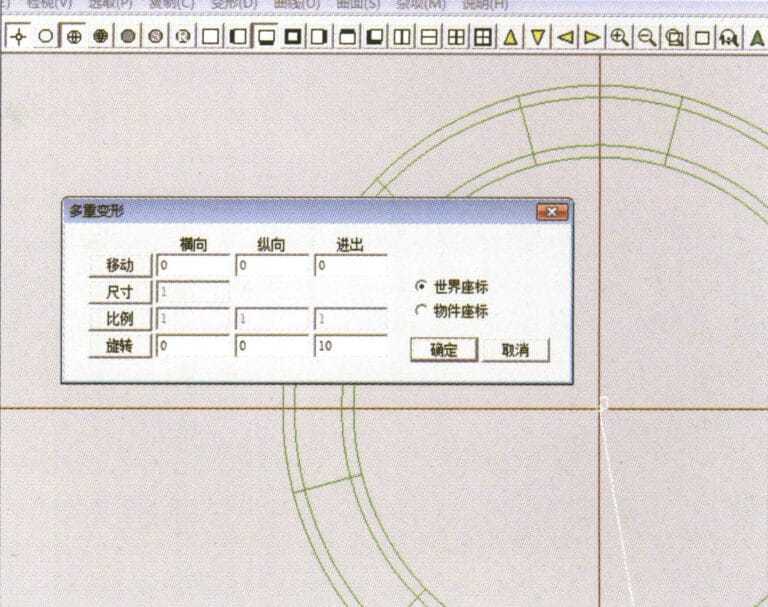
26. Wählen Sie in der Menüleiste "Verformung" > "Mehrfachverformung", um das Dialogfeld "Mehrfachverformung" aufzurufen, geben Sie die entsprechenden Werte ein und bestätigen Sie
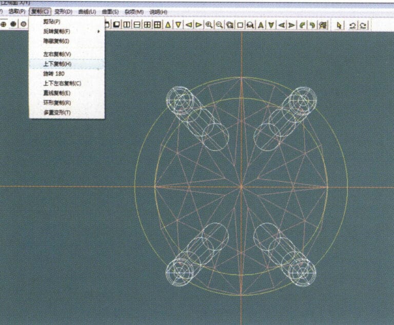
27. Wählen Sie "Kopieren" > "Nach oben und unten kopieren" in der Menüleiste, um die gezeichneten Hilfslinien zu kopieren
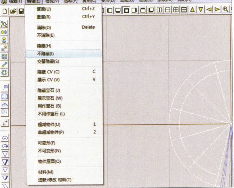
28. Wählen Sie im Menü "Bearbeiten" > "Einblenden", um die ausgeblendeten Kurven anzuzeigen
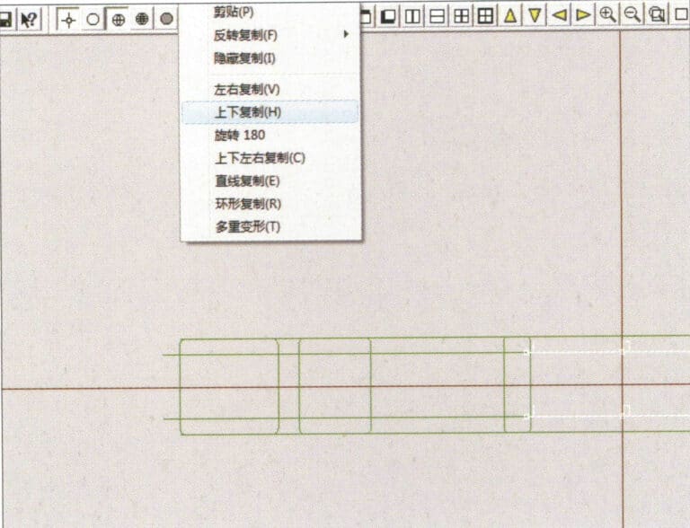
29. Wählen Sie in der Menüleiste "Kopieren" > "Nach oben und unten kopieren", um die ausgewählte Kurve zu kopieren.
30. Wählen Sie Kurven/Flächen im Uhrzeigersinn aus, um Linien-Flächen-Verbindungen zu erstellen, und wählen Sie dann "Fläche" > "Kappenfläche" in der Menüleiste
31. Wählen Sie "Ansicht" > "Schattenkarte" in der Menüleiste, um die Schatteneffekte zu prüfen
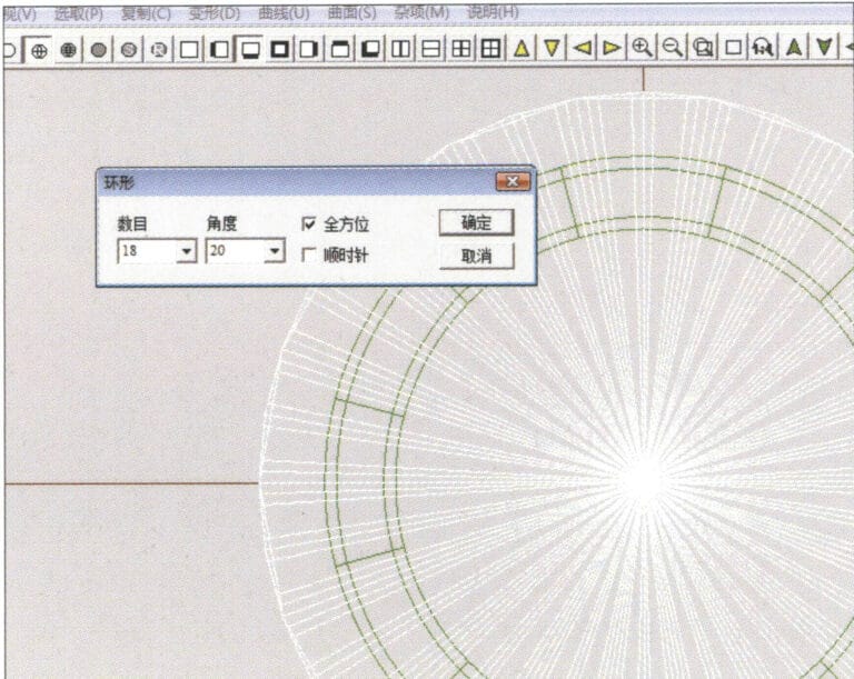
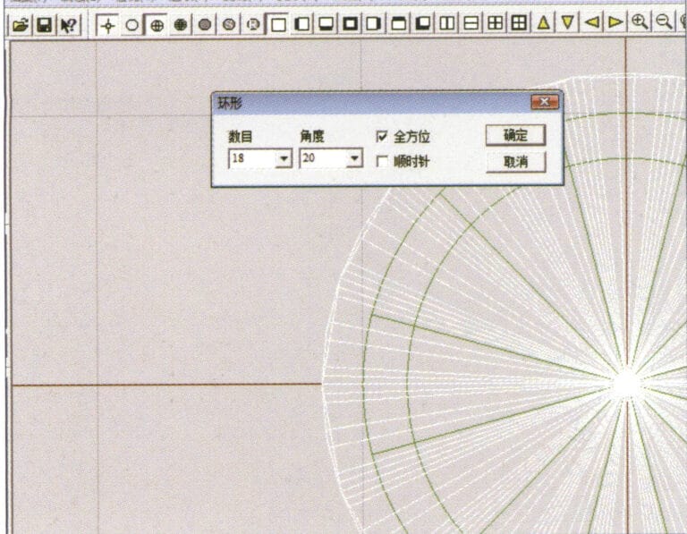
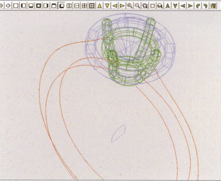
32. Wählen Sie in der Menüleiste "Kopieren" > "Zirkuläre Kopie", geben Sie die entsprechenden Werte ein und bestätigen Sie
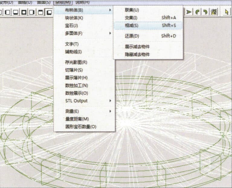
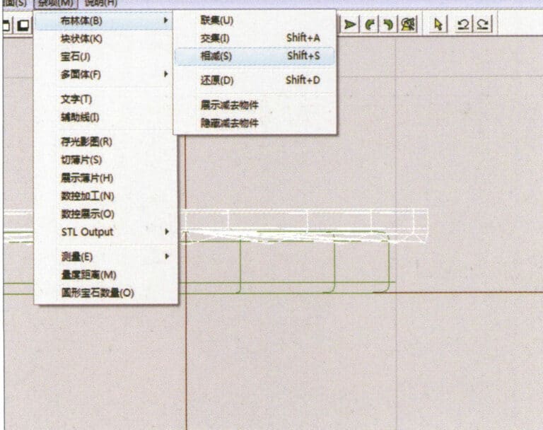
33. Wählen Sie in der Menüleiste "Verschiedenes" > "Boolesch" > "Subtrahieren", um die ausgewählte Fläche von der bereits vereinigten Fläche zu subtrahieren
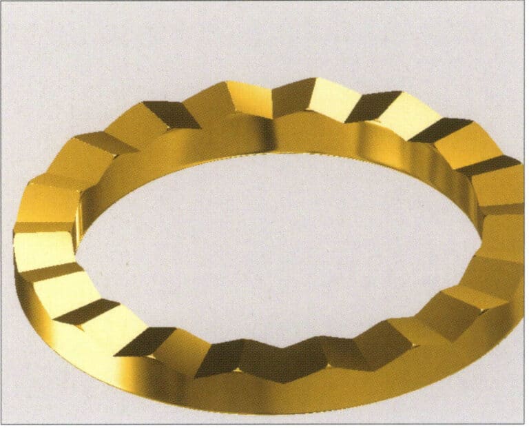
34. Wählen Sie in der Menüleiste "Ansicht" > "Schattenkarte", um die Schatteneffekte zu prüfen
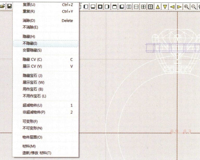
35. Wählen Sie in der Menüleiste "Bearbeiten" > "Einblenden", um die ausgeblendeten Objekte anzuzeigen
36. Wählen Sie in der Menüleiste "Kurve" > "Links-Rechts-Symmetrielinie", um den Innendurchmesser der Ringwand zu zeichnen
37. Wählen Sie in der Menüleiste "Kurve" > "Links-Rechts-Symmetrielinie", um den Außendurchmesser der Ringwand zu zeichnen
38. Wählen Sie in der Menüleiste "Kurve" > "Links-Rechts-Symmetrielinie", um einen Ausschnitt des Ringschaftes zu zeichnen
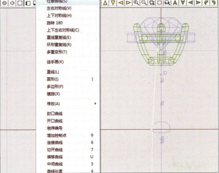
39. Wählen Sie "Kurve" > "Freiformkurve" in der Menüleiste, um eine Hilfslinie zu zeichnen
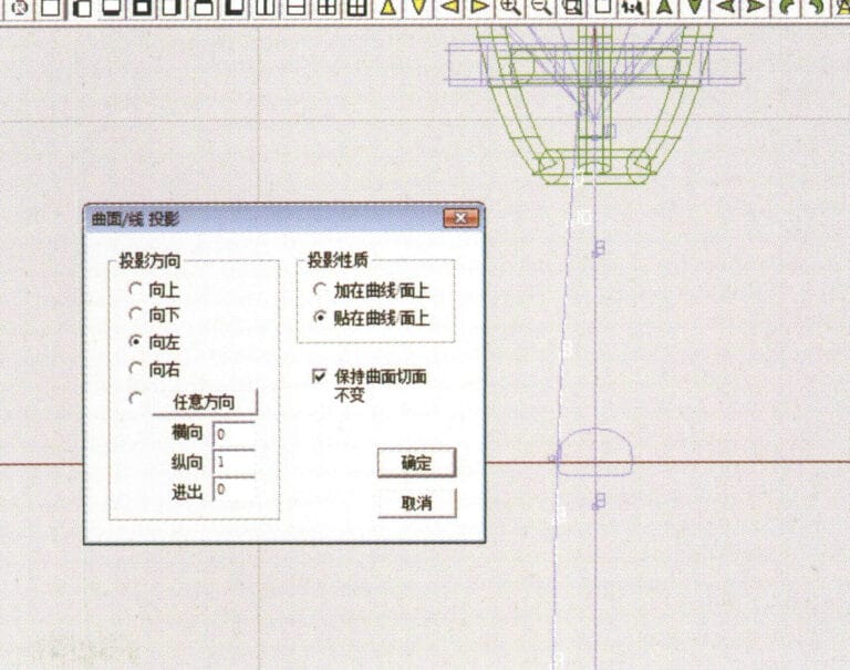
40. Wählen Sie in der Menüleiste "Verformung" > "Flächen-/Linienprojektion", um die Dialogbox "Flächen-/Linienprojektion" aufzurufen, geben Sie die entsprechenden Werte ein und bestätigen Sie
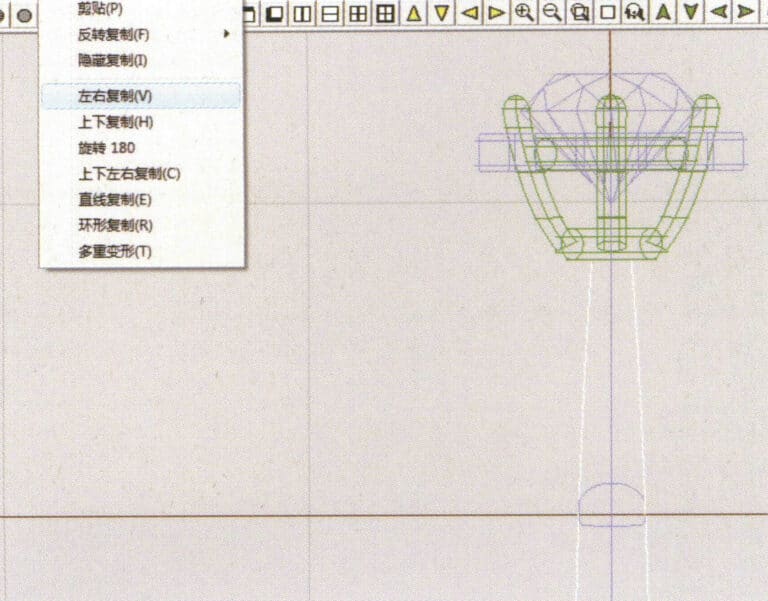
41. Wählen Sie in der Menüleiste "Kopieren" > "Links und rechts kopieren", um den Innendurchmesser des Ringschaftes zu kopieren
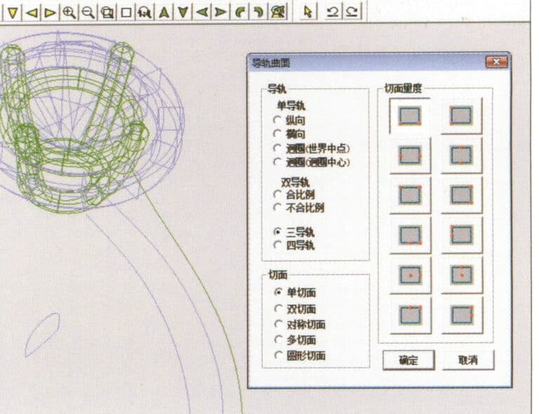
42. Wählen Sie in der Menüleiste "Oberfläche" > "Schienenoberfläche", um das Dialogfeld "Schienenoberfläche" aufzurufen, wählen Sie die entsprechenden Optionen und bestätigen Sie
43. Wählen Sie eine Kurve als linke Führungsschiene und dann eine Kurve als rechte Führungsschiene

44. Wählen Sie eine Kurve als obere Führungsschiene
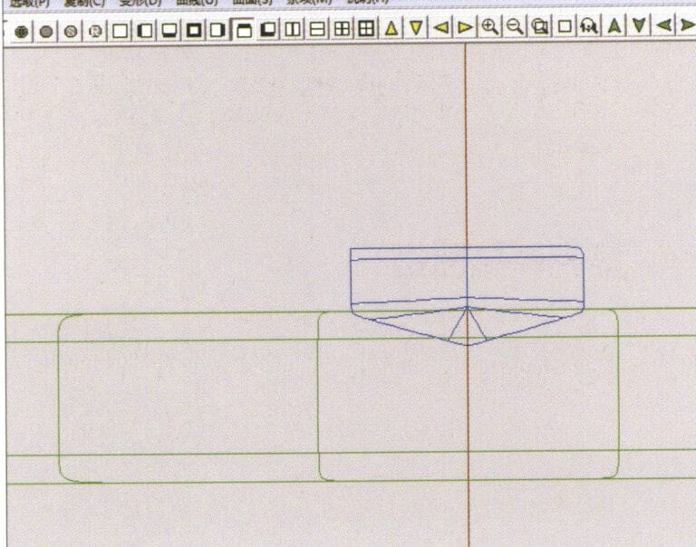
45. Wählen Sie eine Kurve als Querschnitt für die Führungsfläche.
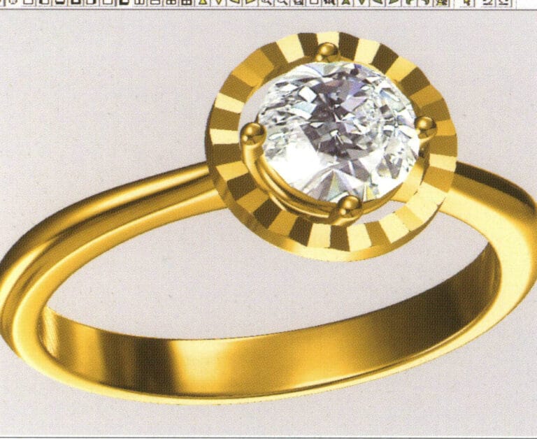
46. Wählen Sie in der Menüleiste "Ansicht" > "Licht- und Schattenkarte", um die Licht- und Schatteneffekte zu untersuchen
47. Wählen Sie in der Menüleiste "Datei" > "Speichern unter", um die Datei zu speichern

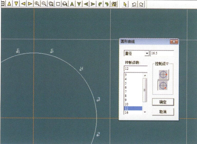
1. Legen Sie in JewelCAD eine neue Datei an, wählen Sie in der Menüleiste "Kurve" > "Kreiskurve", geben Sie im Dialogfeld "Kreiskurve" die entsprechenden Werte als Außenkurve des Rings ein und bestätigen Sie
2. Wählen Sie in der Menüleiste "Kurve" > "Kreiskurve", geben Sie im Dialogfeld "Kreiskurve" die entsprechenden Werte ein, um die innere Kurve des Rings festzulegen, und bestätigen Sie
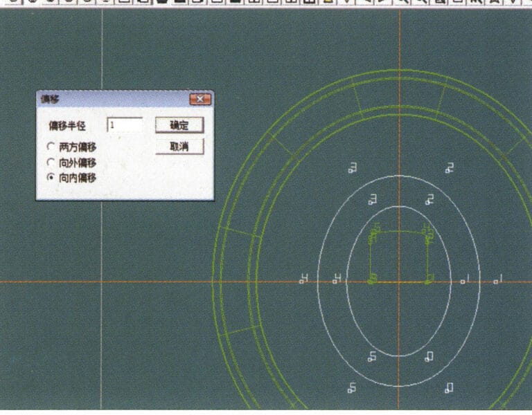
3. Wählen Sie in der Menüleiste "Bearbeiten" > "Verschieben", um die ausgewählte innere Kurve des Rings zu verschieben
4. Wählen Sie "Kopieren" > "Links und rechts kopieren" in der Menüleiste, um die Kurve des inneren Kreises des Rings zu kopieren
5. Wählen Sie in der Menüleiste "Kurve" > "Links-Rechts-Symmetrielinie" als Querschnitt des Ringbandes
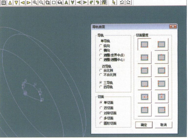
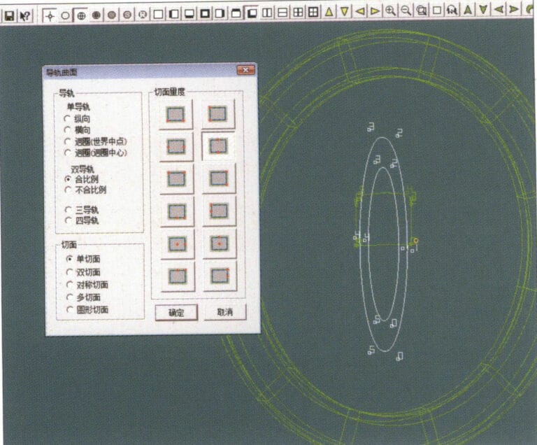
6. Wählen Sie in der Menüleiste "Gebogene Oberfläche" > "Führungsschienenoberfläche", rufen Sie das Dialogfeld "Führungsschienenoberfläche" auf, wählen Sie die entsprechenden Optionen und bestätigen Sie
7. Wählen Sie eine Kurve als die richtige Führungsschiene
8. Wählen Sie eine Kurve als obere Führungsschiene
9. Wählen Sie den Querschnitt des Ringbandes als Querschnitt der Leitkurvenfläche
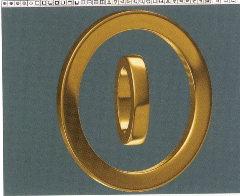
10. Wählen Sie in der Menüleiste "Ansicht" > "Schattenkarte", um die Schatteneffekte zu prüfen
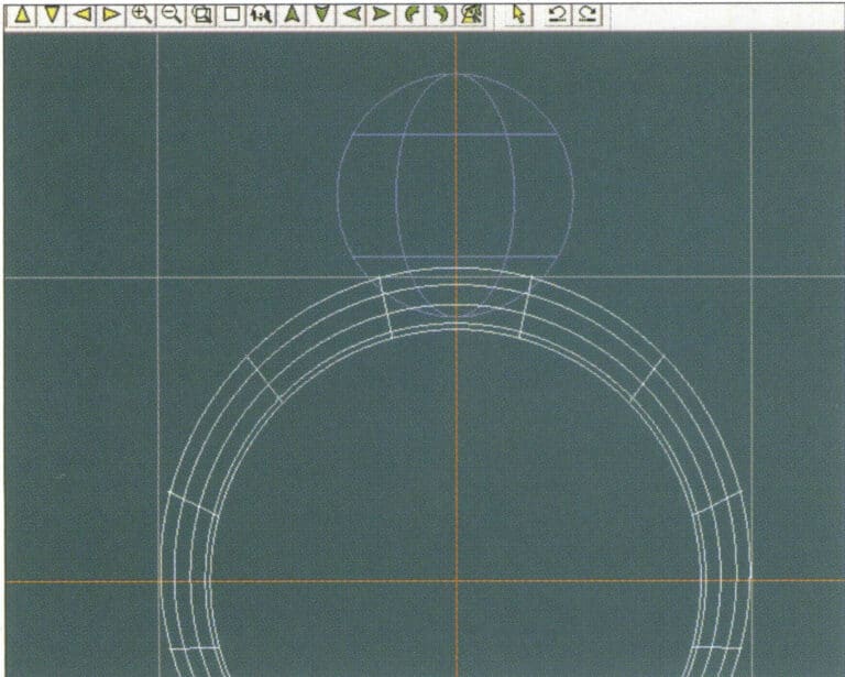
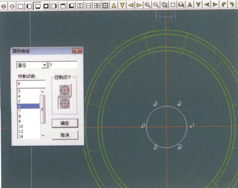
11. Wählen Sie in der Menüleiste "Kurve" > "Kreiskurve", geben Sie im Dialogfenster "Kreiskurve" die entsprechenden Werte als Hilfslinien ein und bestätigen Sie
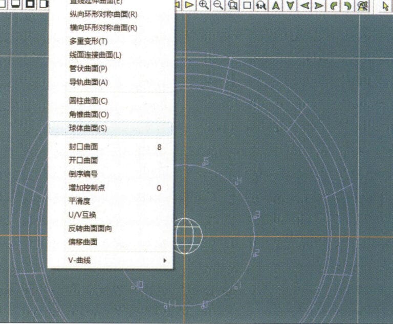
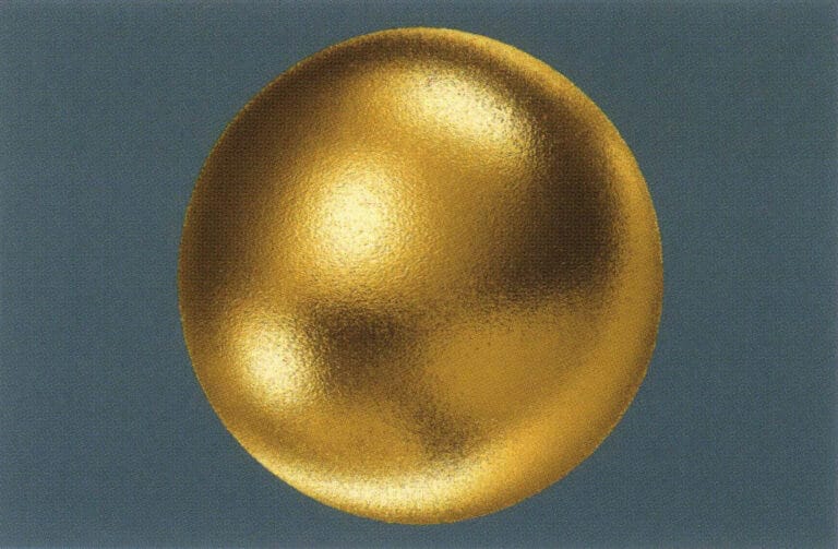
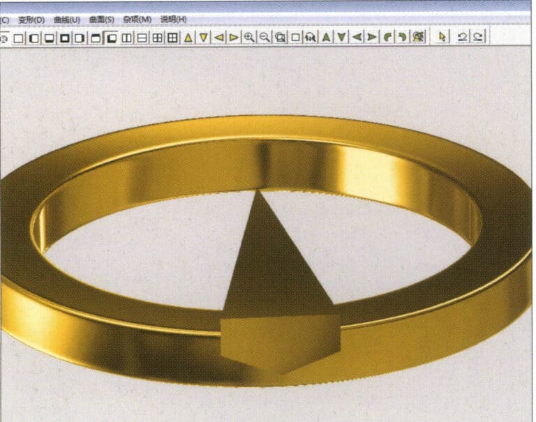
12. Wählen Sie in der Menüleiste "Fläche" > "Kugeloberfläche".
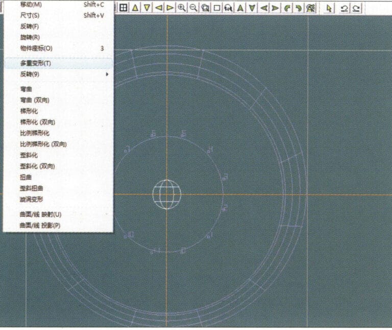
13. Wählen Sie "Verformung" > "Mehrfache Verformung" aus der Menüleiste, um die Kugel zu vergrößern
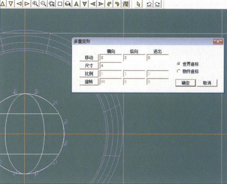
14. Rufen Sie das Dialogfeld "Mehrfachverformung" auf, geben Sie die entsprechenden Werte ein, um die Kugel auf die Breite der Hilfslinien zu vergrößern, und bestätigen Sie
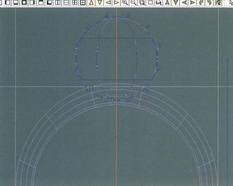
15. Wählen Sie in der Menüleiste "Bearbeiten" > "Verschieben", um sowohl die Kugel als auch die Hilfslinie gleichzeitig zu verschieben
16. Wählen Sie "Bearbeiten" > "Verschieben" in der Menüleiste, um die Hilfslinien zu entfernen
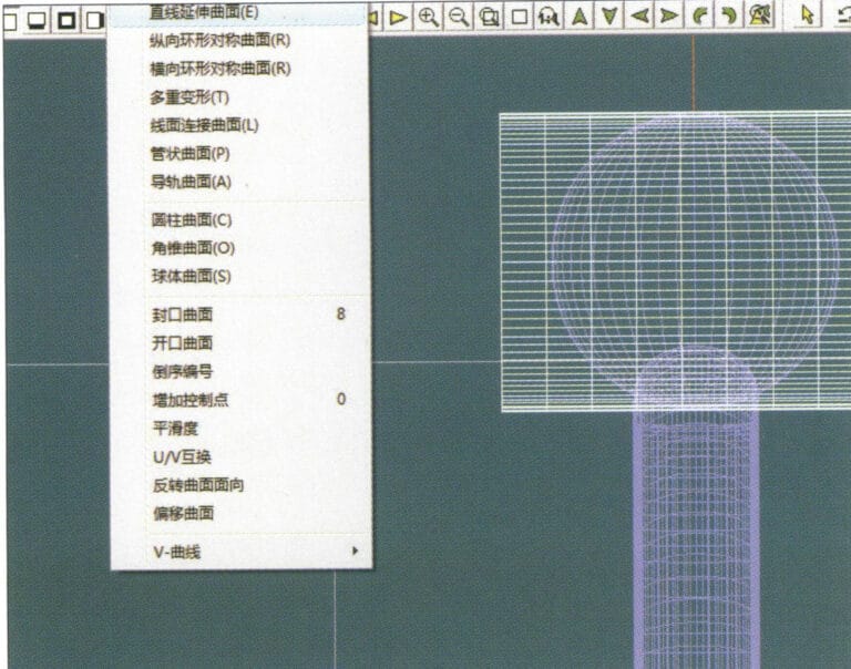
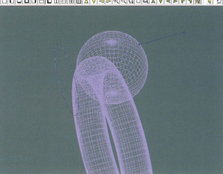
17. Wählen Sie in der Menüleiste "Fläche" > "Gerade Fläche verlängern", um die Hilfslinie zu einer Hilfsfläche zu verlängern
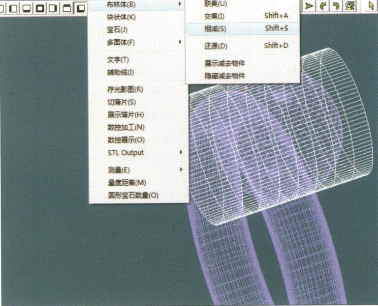
18. Wählen Sie in der Menüleiste "Verschiedenes" > "Boolesch" > "Subtrahieren", um die entsprechenden Teile des Hilfsflächenrings zu subtrahieren
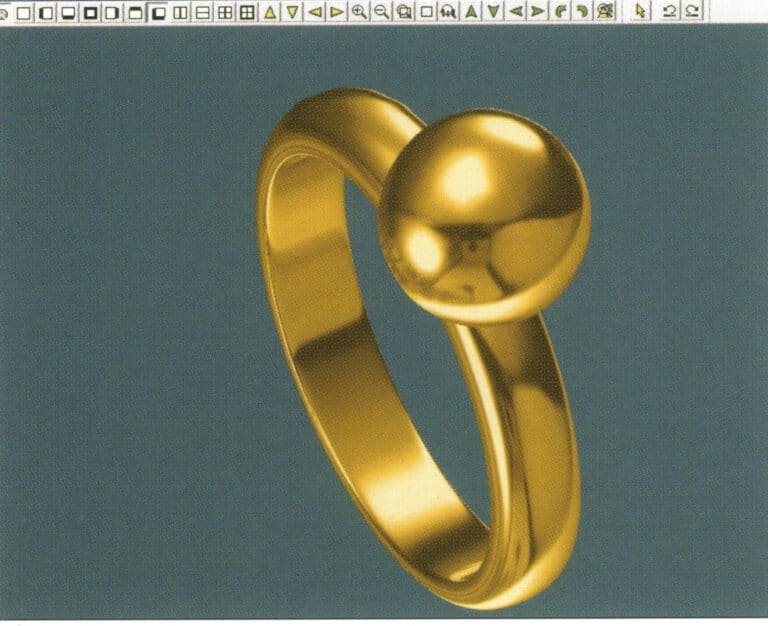
19. Wählen Sie in der Menüleiste "Ansicht" > "Schattenkarte", um die Schatteneffekte zu prüfen
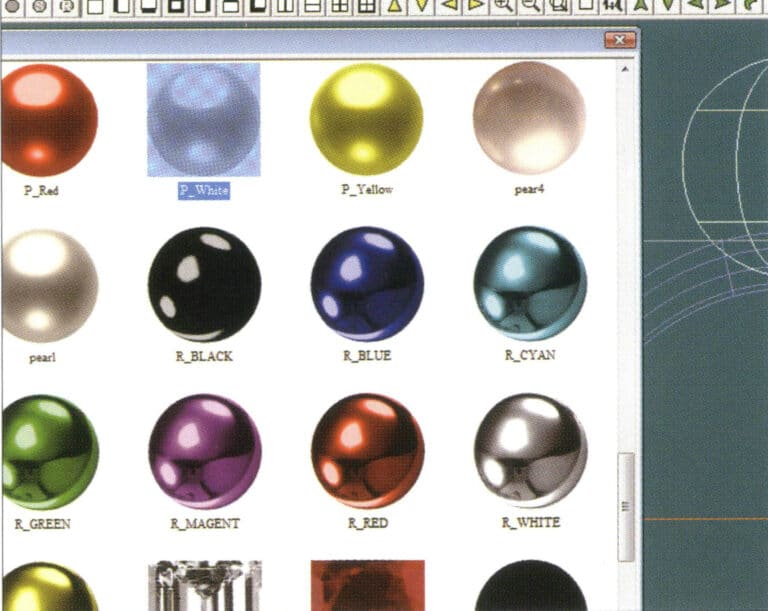
20. Wählen Sie die Kugel aus, gehen Sie in der Menüleiste auf "Bearbeiten" > "Materialien", rufen Sie das Dialogfeld "Materialien" auf, wählen Sie das Material "weiße Perle" und bestätigen Sie
21. Wählen Sie das Ringband aus und wählen Sie dann "Bearbeiten" > "Materialien" in der Menüleiste
22. Rufen Sie das Dialogfeld "Materialien" auf, wählen Sie das entsprechende Material und bestätigen Sie
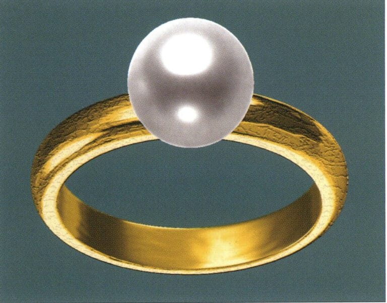
23. Wählen Sie "Ansicht" > "Schattenkarte" in der Menüleiste, um die Licht- und Schatteneffekte zu untersuchen
24. Wählen Sie in der Menüleiste "Datei" > "Speichern unter", um die Datei zu speichern

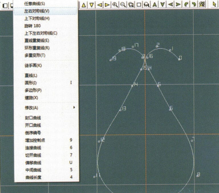
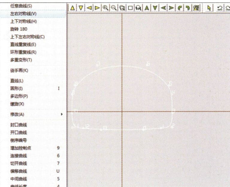
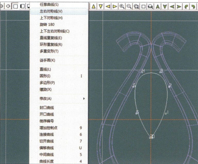
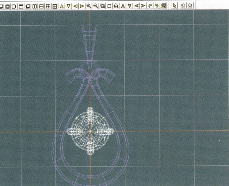
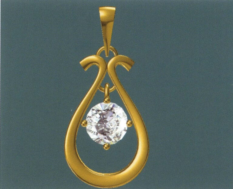
1. Erstellen Sie eine neue Datei in JewelCAD, wählen Sie in der Menüleiste "Kurve" > "Links-Rechts-Symmetrische Linie" und zeichnen Sie die innere Konturlinie des Anhängers
2. Wählen Sie in der Menüleiste "Kurve" > "Links-Rechts-Symmetrische Linie", um die äußere Konturlinie des Hängers zu zeichnen (beachten Sie, dass die Kontrollpunkte der inneren Konturlinie und der äußeren Konturlinie die gleiche Richtung und Menge haben sollten).
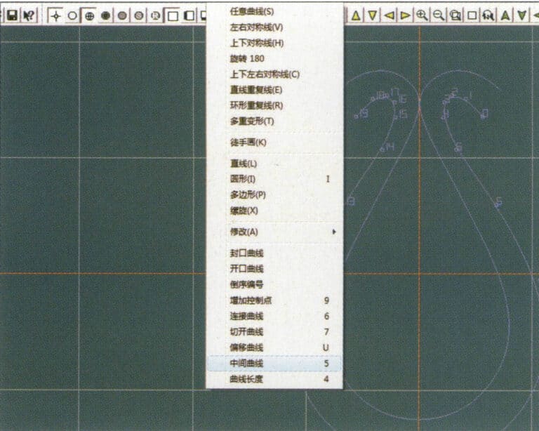
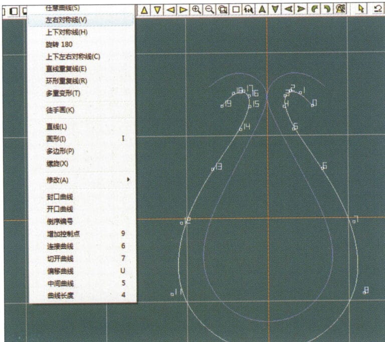
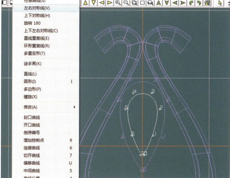
3. Wählen Sie in der Menüleiste "Kurve" > "Mittlere Kurve".
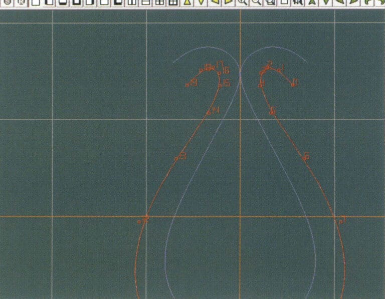
4. Wählen Sie zwei Kurven aus, um die mittlere Kurve zu erstellen. Wählen Sie zunächst die äußere Konturlinie
5. Wählen Sie zwei Kurven, um die mittlere Kurve zu erstellen, und wählen Sie dann die innere Konturlinie
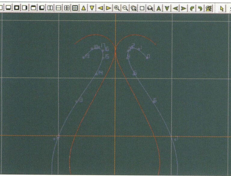
6. Ansicht der bereits erstellten Zwischenkurven
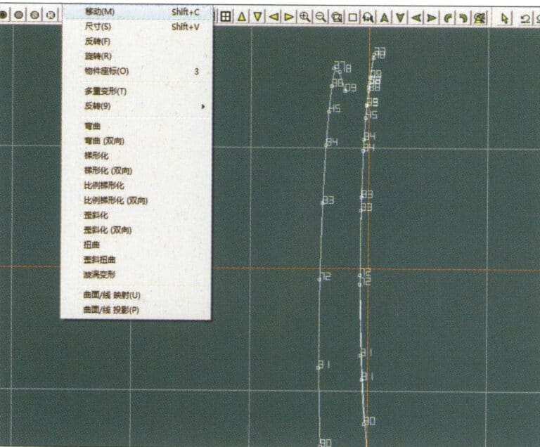
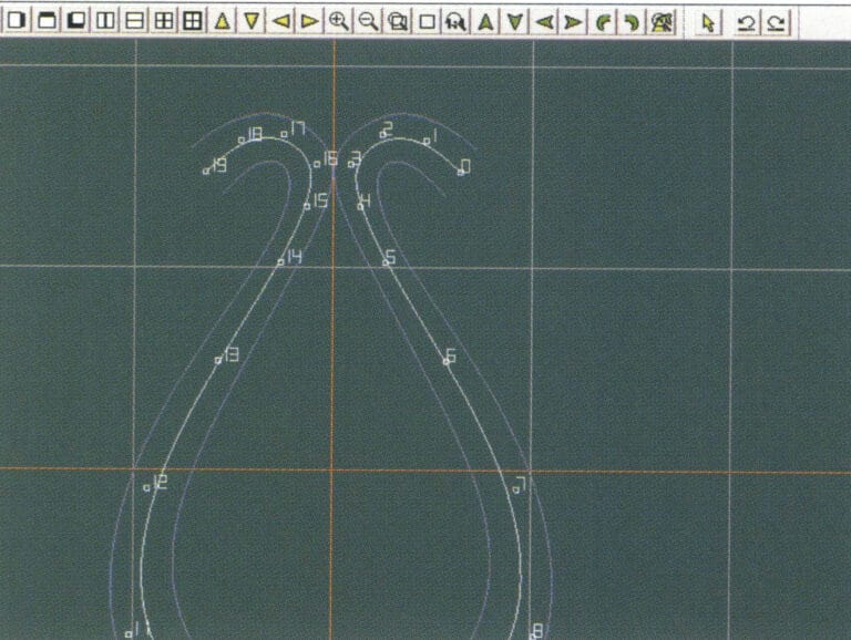
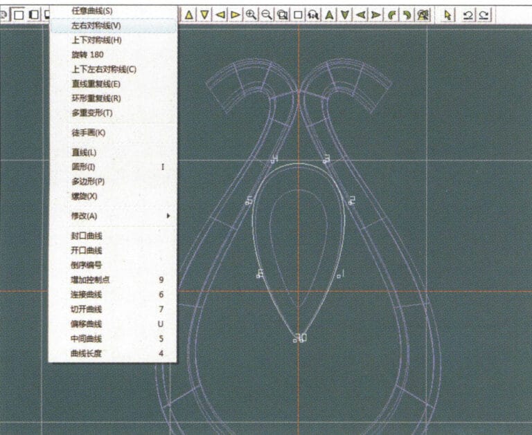
7. Wählen Sie in der Menüleiste "Verformung" > "Verschieben", um den CV und den CV der Konturlinie zu verschieben
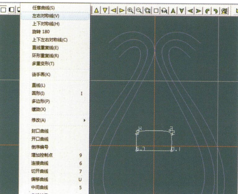
8. Wählen Sie "Kurve" > "Links-Rechts-Symmetrielinie" in der Menüleiste, um einen Querschnitt zu erstellen
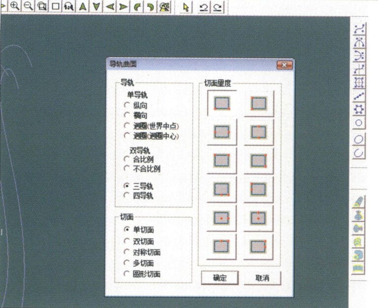
9. Wählen Sie in der Menüleiste "Oberfläche" > "Schienenoberfläche", rufen Sie das Dialogfeld "Schienenoberfläche" auf, um die entsprechenden Optionen auszuwählen, und bestätigen Sie; wählen Sie eine Kurve als linke Kurve, ausgehend von der linken Kurve im Uhrzeigersinn, klicken Sie mit der linken Maustaste auf die Kurve als Schiene, und wählen Sie dann eine andere Kurve als Abschnitt der Schienenoberfläche
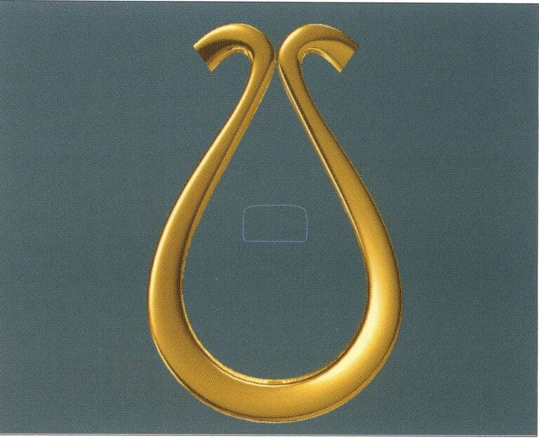
10. Wählen Sie in der Menüleiste "Ansicht" > "Schattenkarte", um die Schatteneffekte zu prüfen
11. Wählen Sie in der Menüleiste "Kurve" > "Links-Rechts-Symmetrielinie", um die äußere Konturlinie des kernförmigen Kipphebels zu zeichnen
12. Wählen Sie in der Menüleiste "Kurve" > "Links-Rechts-Symmetrielinie", um die innere Konturlinie des kernförmigen Kipphebels zu zeichnen
13. Wählen Sie in der Menüleiste "Kurve" > "Links-Rechts-Symmetrielinie", und zeichnen Sie die untere dunkle Linie der Mitte des samenförmigen Kipphebels
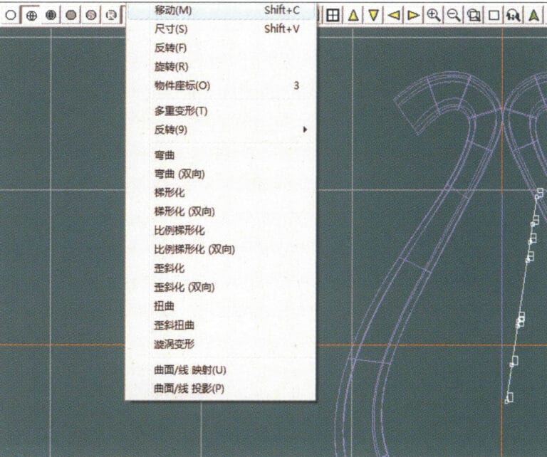
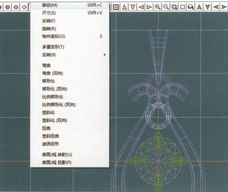
14. Wählen Sie "Verformung" > "Verschieben" in der Menüleiste, um den samenförmigen CV zu verschieben.
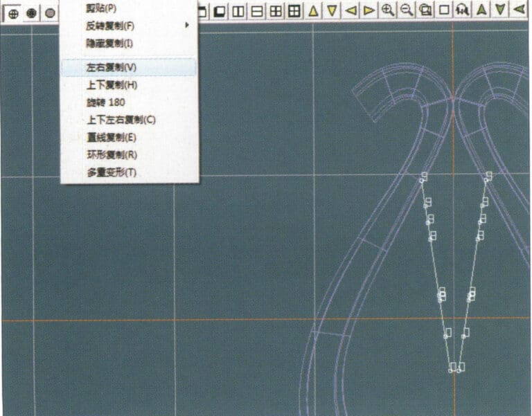
15. Wählen Sie "Kopieren" > "Links und rechts kopieren" in der Menüleiste, um die Kurve des samenförmigen Kipphebels zu kopieren
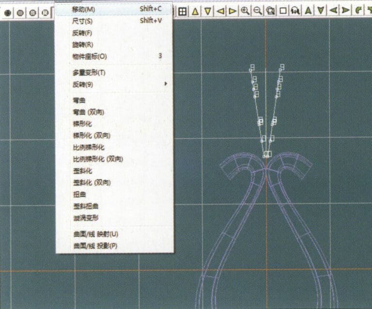
16. Wählen Sie in der Menüleiste "Verformung" > "Verschieben", um die Melonenkernknickkurve zu verschieben
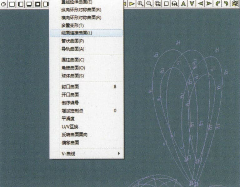
17. Wählen Sie in der Menüleiste "Fläche" > "Linien-Flächen-Verbindungsfläche" und wählen Sie die Kurve/Fläche im Uhrzeigersinn, um eine Linien-Flächen-Verbindungsfläche zu erstellen, und wählen Sie dann "Kurve" > "Geschlossene Fläche" in der Menüleiste.
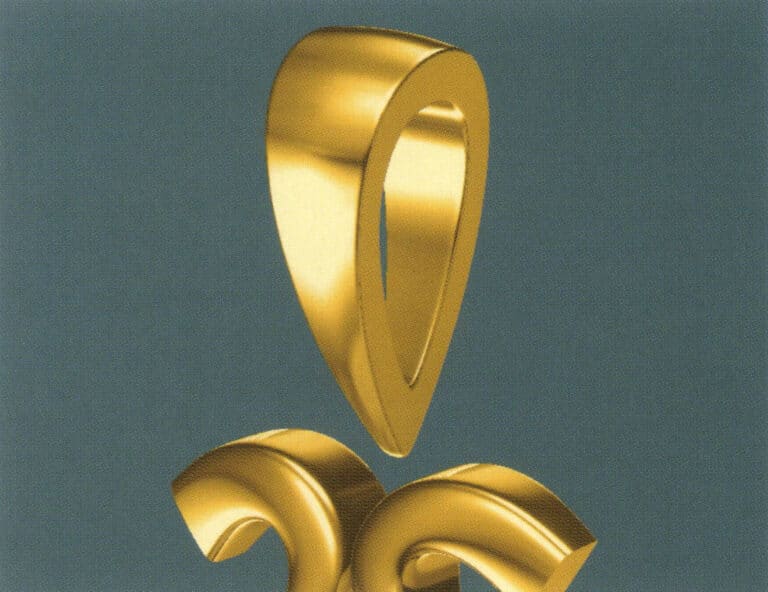
18. Wählen Sie in der Menüleiste "Ansicht" > "Schattenkarte", um die Schatteneffekte zu untersuchen
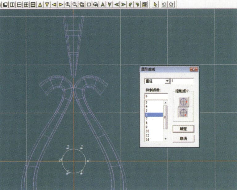
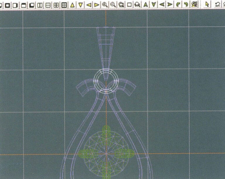
19. Wählen Sie in der Menüleiste "Kurve" > "Kreisförmige Kurve", geben Sie die entsprechenden Werte ein und bestätigen Sie

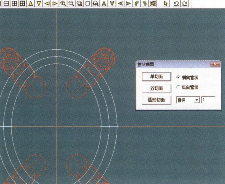
20. Wählen Sie in der Menüleiste "Oberfläche" > "Rohrförmige Oberfläche".
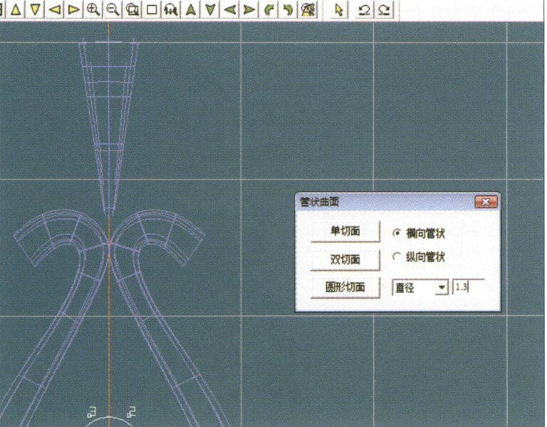
21. Rufen Sie das Dialogfeld "Tubular Surface" auf, geben Sie die entsprechenden Werte ein, klicken Sie auf den Kreisausschnitt und bestätigen Sie
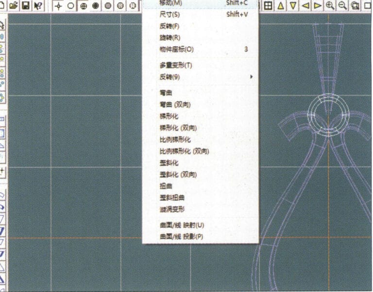
22. Wählen Sie "Verformung" > "Verschieben" in der Menüleiste, um die Ringschnalle zu verschieben

23. Wählen Sie in der Menüleiste "Datei" > "Datei einfügen".
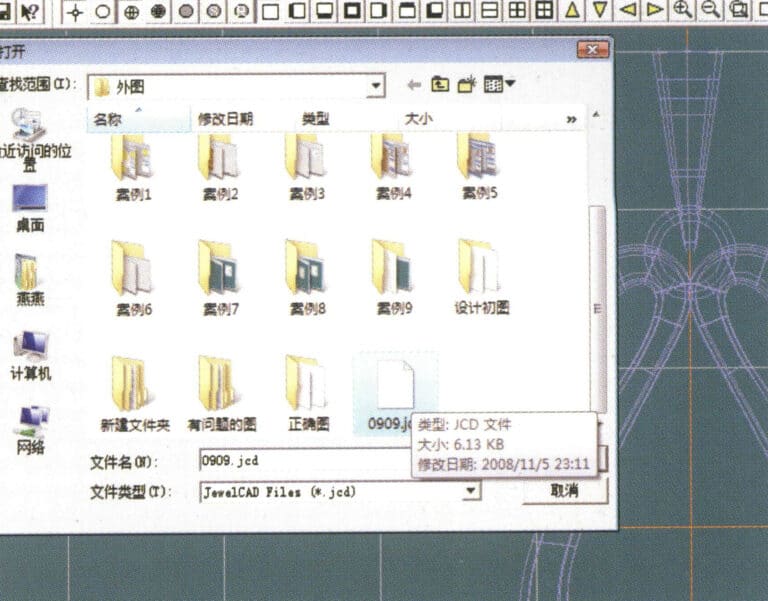
24. Rufen Sie das Dialogfeld "Datei einfügen" auf, wählen Sie das gewünschte Dokument aus und bestätigen Sie
25. Die eingefügte Datei anzeigen - Edelstein
26. Wählen Sie in der Menüleiste "Kopieren" > "Nach oben und unten kopieren", um den ausgewählten Umschalter zu kopieren
27. Wählen Sie in der Menüleiste "Verformung" > "Verschieben", um den horizontalen Ringknebel zu verschieben
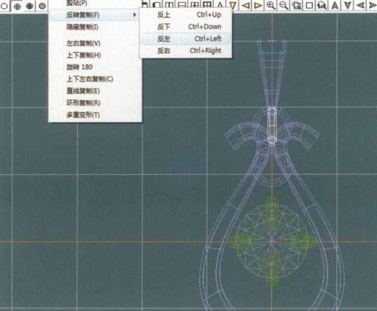
28. Wählen Sie in der Menüleiste "Kopieren" > "Umgekehrte Kopie" > "Links umkehren", um einen vertikalen Umschaltring zu erstellen
29. Wählen Sie in der Menüleiste "Verformung" > "Verschieben", um den horizontalen Ringknebel zu verschieben
30. Wählen Sie in der Menüleiste "Ansicht" > "Schattenkarte", um die Licht- und Schatteneffekte zu untersuchen
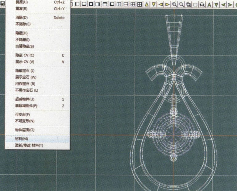
31. Wählen Sie "Bearbeiten" > "Materialien" in der Menüleiste, um die Materialien des ausgewählten Objekts zu ändern
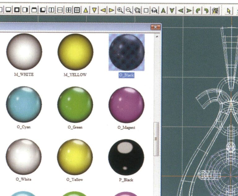
32. Öffnen Sie das Dialogfeld "Materialien", wählen Sie Schwarzgold und bestätigen Sie
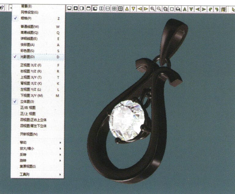
33. Wählen Sie "Ansicht" > "Schattenkarte" in der Menüleiste, um die Schatteneffekte zu prüfen
34. Wählen Sie in der Menüleiste "Datei" > "Speichern unter", um die Datei zu speichern
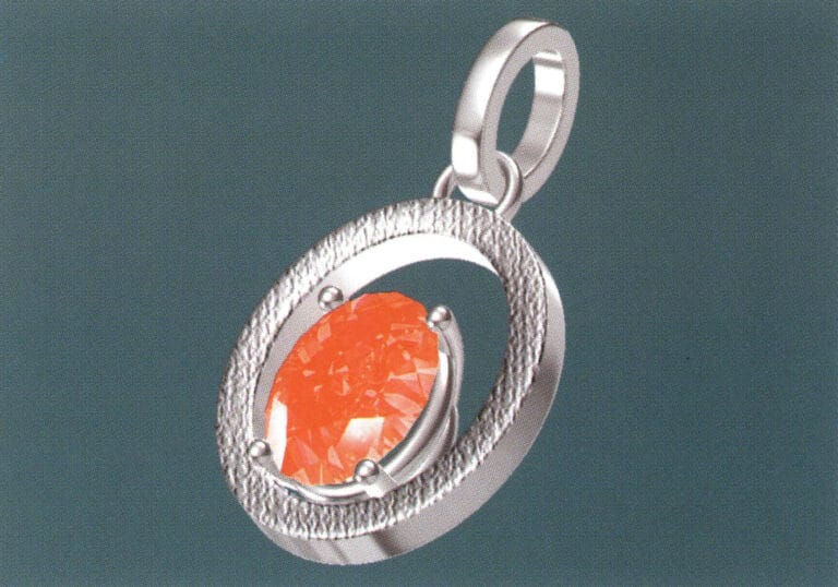
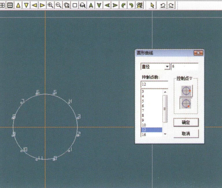
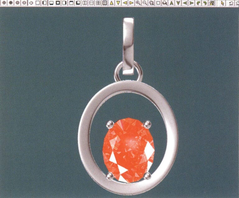
1. Legen Sie in JewelCAD eine neue Datei an, wählen Sie in der Menüleiste "Kurve" > "Kreiskurve", geben Sie im Dialogfenster "Kreiskurve" als innere Hilfslinie die entsprechenden Werte ein und bestätigen Sie

2. Wählen Sie in der Menüleiste "Kurve" > "Kreiskurve", geben Sie im Dialogfeld "Kreiskurve" die entsprechenden Werte als externe Hilfslinie ein und bestätigen Sie
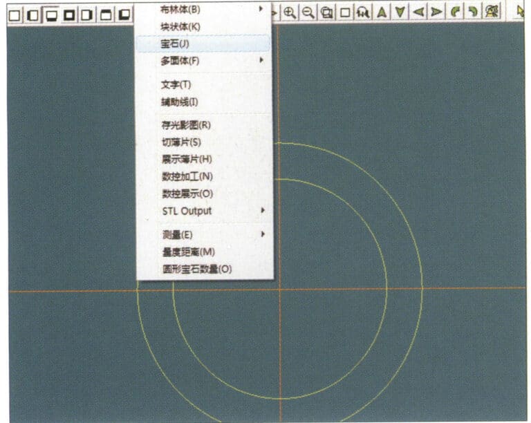
3. Wählen Sie "Verschiedenes" > "Edelsteine" in der Menüleiste
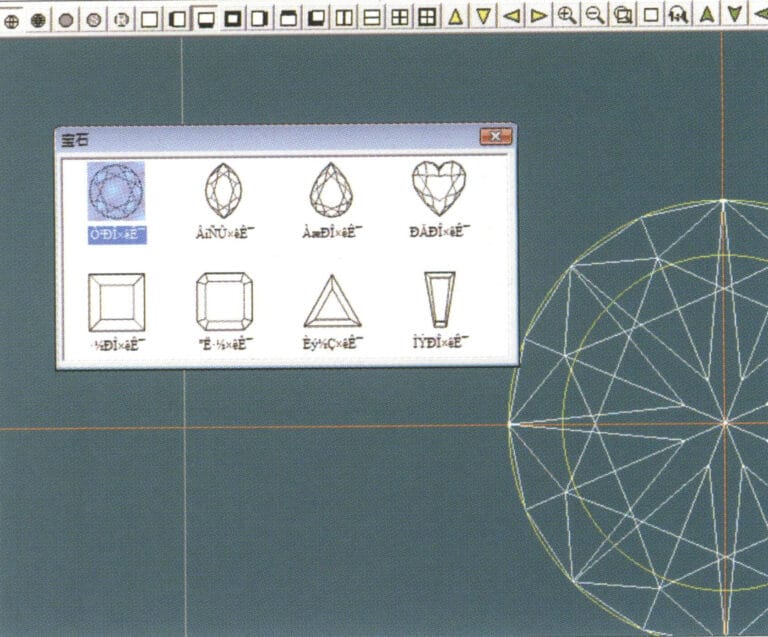
4. Öffnen Sie das Dialogfeld "Edelsteine", wählen Sie die entsprechenden Edelsteine aus und bestätigen Sie
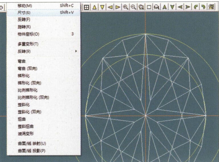
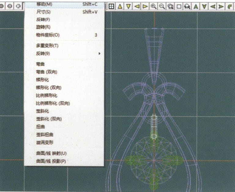
5. Wählen Sie in der Menüleiste "Verformung" > "Größe", um den runden Edelstein in einen ovalen Edelstein zu verwandeln.
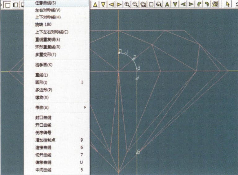
6. Wählen Sie in der Menüleiste "Kurve" > "Freiformkurve", um eine krallenförmige Hilfslinie zu zeichnen
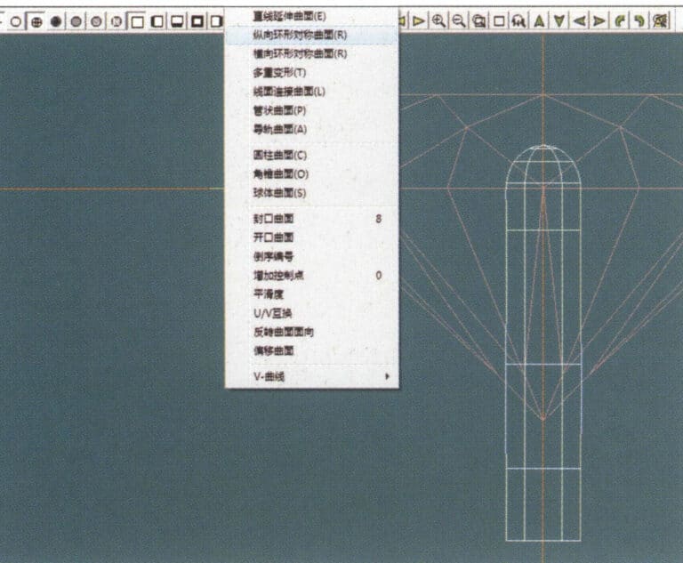
7. Wählen Sie in der Menüleiste "Fläche" > "Längssymmetrische Kreisfläche" und zeichnen Sie eine Klauenform
8. Wählen Sie "Kopieren" > "Links und rechts kopieren" in der Menüleiste, um die Krallenform zu kopieren.
9. Wählen Sie in der Menüleiste "Kopieren" > "Nach oben und unten kopieren", um die Krallenform erneut zu kopieren
10. Wählen Sie in der Menüleiste "Verformung" > "Größe", um die kreisförmige Hilfslinie in eine elliptische Hilfslinie zu ändern
11. Wählen Sie in der Menüleiste "Gekrümmte Oberfläche" > "Rohrförmige Oberfläche", geben Sie die entsprechenden Werte im Dialogfeld "Rohrförmige Oberfläche" ein und bestätigen Sie
12. Wählen Sie in der Menüleiste "Kurve" > "Offset-Kurve".
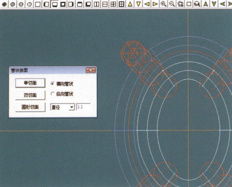
13. Wählen Sie in der Menüleiste "Oberfläche" > "Röhrenoberfläche", geben Sie die entsprechenden Werte ein und bestätigen Sie
14. Wählen Sie in der Menüleiste "Ansicht" > "Schattenkarte", um die Schatteneffekte zu untersuchen und die Einstellung zu überprüfen
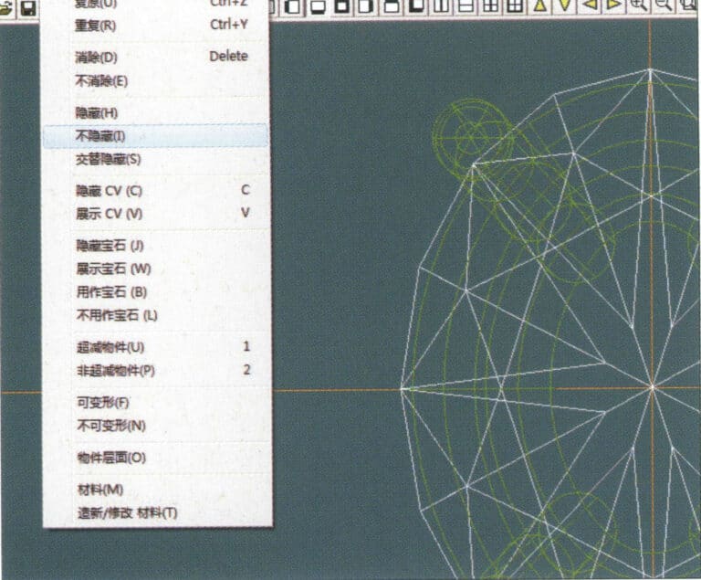
15. Wählen Sie in der Menüleiste "Bearbeiten" > "Einblenden", um die verborgenen Edelsteine anzuzeigen
16. Wählen Sie "Bearbeiten" > "Materialien" in der Menüleiste
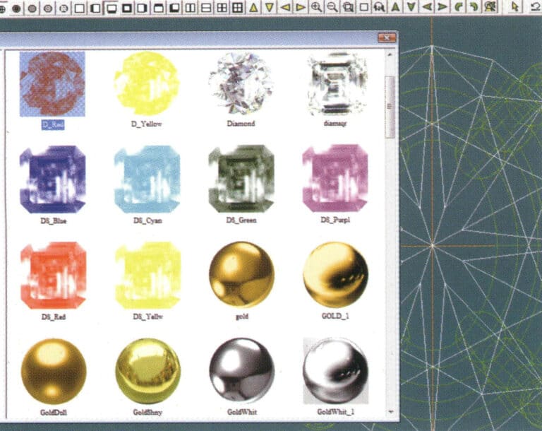
17. Öffnen Sie das Dialogfeld "Materialien", wählen Sie Rubin und bestätigen Sie
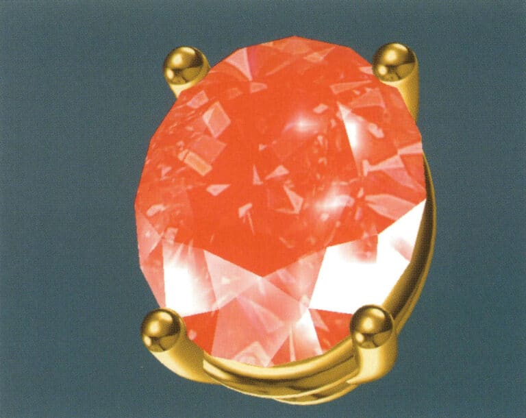
18. Wählen Sie in der Menüleiste "Ansicht" > "Schattenkarte", um die Schatteneffekte zu untersuchen
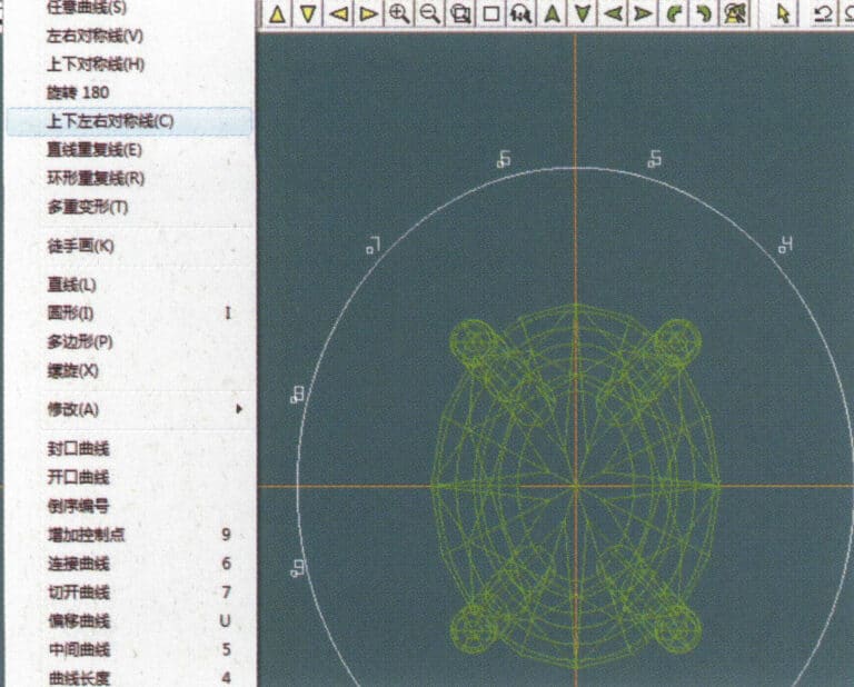
19. Wählen Sie in der Menüleiste "Kurve" > "Vertikale und horizontale Symmetrielinie" als Hilfslinie für den äußeren Kreis
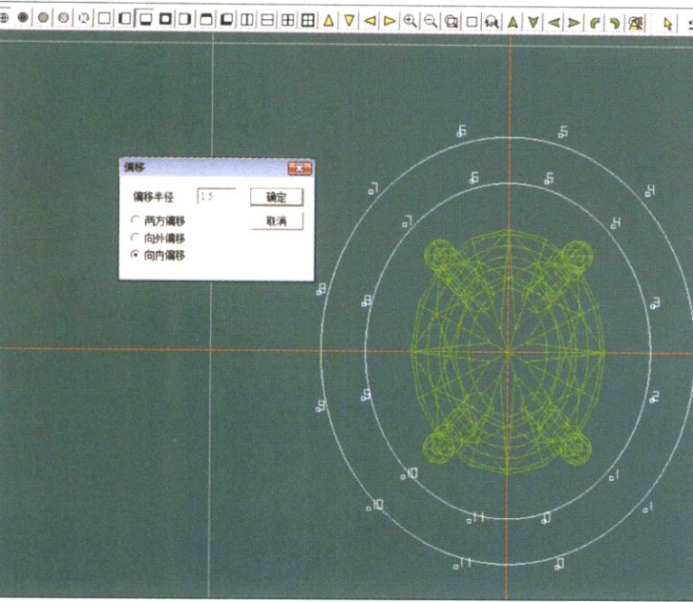
20. Wählen Sie in der Menüleiste "Kurve" > "Offset-Kurve".
21. Rufen Sie das Dialogfeld "Offset-Kurve" auf, geben Sie die entsprechenden Werte als Hilfslinien für den inneren Kreis ein und bestätigen Sie
22. Wählen Sie in der Menüleiste "Kurve" > "Links-Rechts-Symmetrische Linie" als Querschnitt der Spule
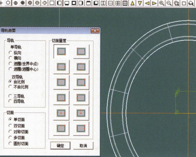
23. Wählen Sie in der Menüleiste "Gebogene Oberfläche" > "Schienenoberfläche", um das Dialogfeld "Schienenoberfläche" aufzurufen, wählen Sie die entsprechenden Optionen und bestätigen Sie
24. Wählen Sie in der Menüleiste "Kurve" > "Kreiskurve", geben Sie im Dialogfeld "Kreiskurve" die entsprechenden Werte ein und bestätigen Sie; klicken Sie mit der linken Maustaste auf eine Kurve als linke Führungskurve, klicken Sie auf eine andere Kurve als rechte Führungsschiene, und wählen Sie dann den Spulenquerschnitt als Querschnitt der Führungsschienenoberfläche; nach Fertigstellung dient er als Hilfslinie für den Außenkreis der Ketteneinfädelposition

25. Nachdem Sie die äußeren Hilfslinien für die Kettenposition fertiggestellt haben, wählen Sie in der Menüleiste "Kurve" > "Offsetkurve".
26. Öffnen Sie das Dialogfeld "Offset-Kurve", geben Sie die entsprechenden Werte ein und bestätigen Sie
27. Wählen Sie in der Menüleiste "Oberfläche" > "Schienenoberfläche", um das Dialogfeld "Schienenoberfläche" aufzurufen, wählen Sie die entsprechenden Optionen und bestätigen Sie, klicken Sie mit der linken Maustaste auf eine Kurve, um sie als linke Schienenkurve festzulegen, klicken Sie auf eine andere Kurve, um sie als rechte Schiene festzulegen, und wählen Sie dann den Spulenquerschnitt als Querschnitt der Schienenoberfläche
28. Wählen Sie in der Menüleiste "Ansicht" > "Schattenkarte", um die Schatteneffekte zu prüfen
29. Wählen Sie in der Menüleiste "Kurve" > "Kreisförmige Kurve", geben Sie die entsprechenden Werte ein und bestätigen Sie
30. Wählen Sie in der Menüleiste "Gekrümmte Oberfläche" > "Röhrenförmige Oberfläche", geben Sie die entsprechenden Werte ein und bestätigen Sie
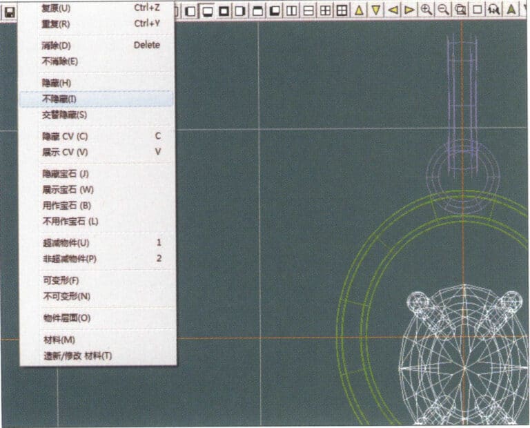
31. Wählen Sie in der Menüleiste "Bearbeiten" > "Einblenden", um die ausgeblendeten Objekte anzuzeigen
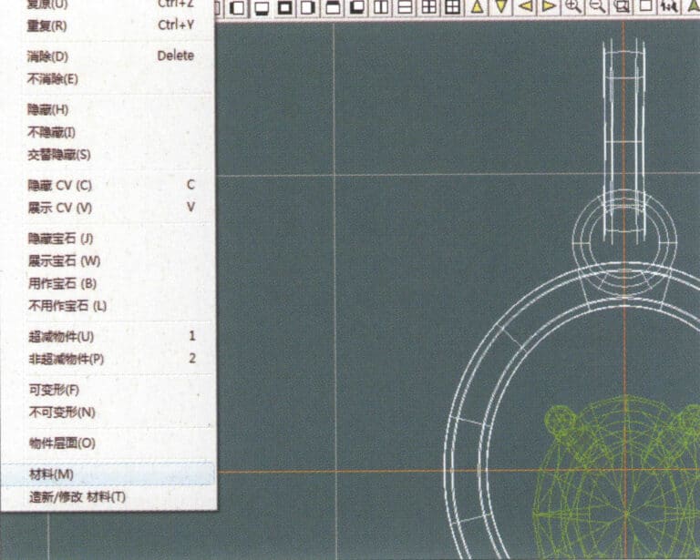
32. Wählen Sie "Bearbeiten" > "Materialien" in der Menüleiste
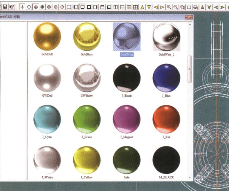
33. Rufen Sie das Dialogfeld "Materialien" auf, wählen Sie die entsprechenden Materialien aus und bestätigen Sie
34. Wählen Sie in der Menüleiste "Ansicht" > "Schattenkarte", um die Schatteneffekte zu prüfen
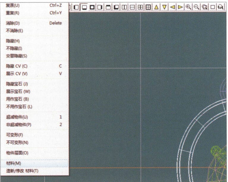
35. Wählen Sie "Bearbeiten" > "Materialien" in der Menüleiste
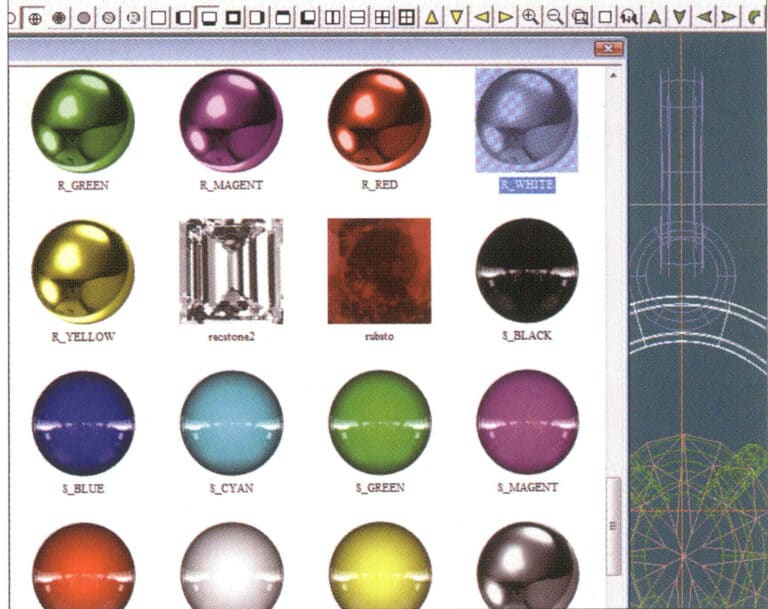
36. Rufen Sie das Dialogfeld "Materialien" auf, wählen Sie die entsprechenden Texturmaterialien aus und bestätigen Sie
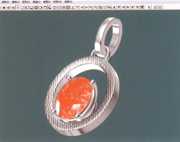
37. Wählen Sie "Ansicht" > "Schattenkarte" in der Menüleiste, um die Schatteneffekte zu prüfen
38. Wählen Sie in der Menüleiste "Datei" > "Speichern unter", um die Datei zu speichern